00 Gauge - Jeff Lynn / SRman's New Layout
Posted
Full Member
Progress (or otherwise) on Jeff's new layout
A couple of shots of the new Heljan class 16 in service. This one is D8404 with Stratford style yellow panels. The model runs almost silently and very smoothly with 20 wagons in tow.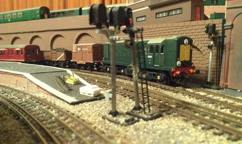
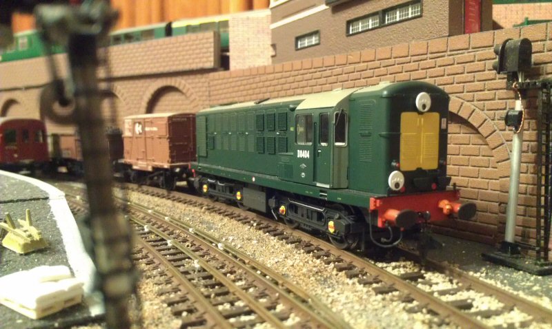
The headcodes I chose for each end are similar to the ones I put on the class 15 and represent transfer freight runs on to the Southern Region, with this one representing Norwood Junction as a destination and the code at the other end (not visible) being for Hither Green.
Jeff Lynn,
Amateur layabout, Professional Lurker, Thread hijacker extraordinaire
Amateur layabout, Professional Lurker, Thread hijacker extraordinaire

Posted
Inactive Member
Posted
Banned
I just hope your model is a little more reliable than the real thing ! Nice little loco. :thumbs…there was always about 3 of them with the side panels off being worked on, such was their unreliability…
Cheers, Gary.
Posted
Full Member
It does look nice and once it has gone out of its warranty period I'll weather it a bit. I had to remove most of the pipe work from the buffer beams to allow the tension lock couplings to be fitted but I may yet add shortened versions of the pipes.
Jeff Lynn,
Amateur layabout, Professional Lurker, Thread hijacker extraordinaire
Amateur layabout, Professional Lurker, Thread hijacker extraordinaire
Posted
Full Member
In painting the rails I disturbed a bit of the loose (or not properly stuck down!) ballast, so I sent the Dapol track cleaner round in front of firstly the Bachmann C class then the Heljan 16, in vacuum cleaner mode. The first video shows just the class 16 with cross-London transfer freight then the second one shows it propelling the Dapol track cleaner, followed by the LT CO/CP stock (which had to be moved to allow painting of the rails then the cleaner to run through where it had been standing).


Jeff Lynn,
Amateur layabout, Professional Lurker, Thread hijacker extraordinaire
Amateur layabout, Professional Lurker, Thread hijacker extraordinaire
Posted
Full Member


There is still so much work to do on this layout but I am proceeding slowly. The viaduct is gradually being added to as well - more pics of that will follow when I have made some more significant progress.
 Last edit: by SRman
Jeff Lynn,
Amateur layabout, Professional Lurker, Thread hijacker extraordinaire
Amateur layabout, Professional Lurker, Thread hijacker extraordinaire
Posted
Site staff
Regards
Alan
Born beside the mighty GWR.
Alan
Born beside the mighty GWR.
Posted
Full Member
They are white metal kits from defunct The Model Shop, Harrow (latterly available from Radley Models), with two Black Beetle motor bogies fitted into one of the DM cars.
I always remember riding in them during my childhood, and still love the sight in my mind's eye of those flared skirts sweeping into the stations.
Last edit: by SRman
Jeff Lynn,
Amateur layabout, Professional Lurker, Thread hijacker extraordinaire
Amateur layabout, Professional Lurker, Thread hijacker extraordinaire
Posted
Site staff
Regards
Alan
Born beside the mighty GWR.
Alan
Born beside the mighty GWR.
Posted
Full Member
I found that running in one direction only, it was derailing at a particular place on the outer radius inside the tunnels but a slight tweak to the track fixed that - it merely needed the inside rail lifted very slightly.
I have not fitted headcodes or any other detail bits myself, yet. One advantage of the Kernow specials is that they pre-fit those fiddly little lifting eyes on the roof, as well as the name and number plates. I'll fit the headcodes from inside the apertures when I'm ready, like I did with their class 22.


Last edit: by SRman
Jeff Lynn,
Amateur layabout, Professional Lurker, Thread hijacker extraordinaire
Amateur layabout, Professional Lurker, Thread hijacker extraordinaire
Posted
Full Member


The Heljan one has lost a windscreen wiper for which I haven't found a replacement yet. I also added the etched plates to it as an improvement over the original printed versions. I must add a little more weathering, particularly along the skirts.
Jeff Lynn,
Amateur layabout, Professional Lurker, Thread hijacker extraordinaire
Amateur layabout, Professional Lurker, Thread hijacker extraordinaire
Posted
Inactive Member
Its good to see your progress on the railway.
Must be fun to operate!
regards,
Derek.
Posted
Full Member
My progress has been somewhat slower than I would really like but I am getting bits done here and there. I keep thinking that I need to finish wiring up the point motors which are in place already.
I also have the control panel diagram so must make up the box so I can add the studs or switches and really finish off the Underground section. There is more third and fourth rail to lay, which is not a difficult task, just tedious.
There is not a huge amount of operation possible on this lower section (by design) as it was intended to allow four trains to be operated easily, two at a time, with a fifth one shuttling in and out of the station or swapping with one of the others.. At a later stage I will add block section controls to allow four trains to run at once (two in each direction) semi-automatically without running into each other.
While not contributing to the layout development itself, I added some of the detail bits to the Dapol/Kernow Western last night. I haven't added every available part but the brake rigging, cab steps and speedometer drives were done (although I managed to break one of those in the process!).


Last edit: by SRman
Jeff Lynn,
Amateur layabout, Professional Lurker, Thread hijacker extraordinaire
Amateur layabout, Professional Lurker, Thread hijacker extraordinaire
Posted
Full Member
Construction was pretty straightforward, although I found the ladder and safety fences rather delicate when cutting them of the sprue. The circuit board that forms the backbone of the signal seems robust and very simple to wire. I haven't. as yet. wired up any of the signals on the layout, although I have tested them briefly to make sure each o them works.
Here are a couple of photos to show the new addition in place. I will certainly be adding more of these signals from Train Tech in the future, replacing hotch-potch of signals from different sources.


One of the Australian signals is visible in the background in that first shot.
Jeff Lynn,
Amateur layabout, Professional Lurker, Thread hijacker extraordinaire
Amateur layabout, Professional Lurker, Thread hijacker extraordinaire
Posted

Site staff
The circuit board with the LEDS already mounted is a good idea & I will agree, the railings, etc are very prone to breaking.
Ron
NCE DCC ; 00 scale UK outline.
NCE DCC ; 00 scale UK outline.
Posted
Full Member
There were a few trials and tribulations on what should have been a simple wiring job. I wired them according to the diagram, using the supplied resistors on the negative common return legs. Each resistor was then joined to a common return negative wire to a 12 volt DC transformer.
The wires to each positive terminal (one red, one green, for each signal) were run to two SPDT on-on switches, with the red wire going to one terminal and the green to the other on each switch, then the centre terminals on the switches were run to the positive output on the transformer.
All well and good so far. This should have given me independent control of each signal aspect, with each individual signal only being able to show red or green, not both.
What actually happened was this:
Selecting green on both switches illuminated both green lights. So far, so good! Selecting red on both switches illuminated both red lights. Again, good! With both signals at green, selecting red on the near signal knocked out the far one altogether. Not so good! With both on red, selecting green on the near signal knocked out the near signal and switched the far one to green.
The problem, in the end was due to my working under the layout with a blue-white light source, which meant I couldn't tell red and orange wires apart!! Once I fixed that up, the result is that both signals are working as they should.

Being a glutton for punishment, I started on the twin-headed junction signal today. This time I was very careful to keep track of the wire colours and where they went. This signal uses a common negative return for all four lights so required four resistors in the four positive lines (one each), where the other two single signals could use one resistor in the negative common.
Anyway, I wired it all up and tested … the left-hand red refused to illuminate. I checked and double-checked the wiring and could find nothing wrong.
After much head scratching, I shorted a screw driver across the relevant terminals on the SPDT switch and lo and behold, the red lit up! So, it was a faulty switch this time. I swapped it for a good one and all is now well with that signal.

Overall, I think the Train Tech signals work well and are easy to put together, with the proviso that one has to be extremely careful cutting the very delicate safety railings and hoops from the sprues. While they aren't entirely accurate representations of LT signals, they look good anyway and I will be purchasing a few more, releasing the hotch-potch of signals already on the layout as place-holders to be used on the main lines, where there tended to be much more of a mixture of types and styles.
Jeff Lynn,
Amateur layabout, Professional Lurker, Thread hijacker extraordinaire
Amateur layabout, Professional Lurker, Thread hijacker extraordinaire
Posted
Inactive Member
Working under baseboards is no joke.
I like those photo,s, Plenty of atmosphere.
Wishing you and your family plus Toby if he is still around.
A very happy Christmas and New Year.
regards,
Derek.
Posted
Full Member
I'd like to wish everyone a very happy Christmas and New Year season.
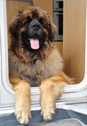
p.s. Toby is fine and has adopted a position under our Christmas tree as his own!

Jeff Lynn,
Amateur layabout, Professional Lurker, Thread hijacker extraordinaire
Amateur layabout, Professional Lurker, Thread hijacker extraordinaire
Posted
Full Member

I have mounted some switches which will be wired up for the two aspect colour light signals. I have already wired up four signal heads, hence the holes where those switches will go; they cannot be mounted until I screw the panel into its final position. It will be hinged to allow easy access to the back.
Point control will be stud and probe, although I am considering changing that to sprung toggle switches (sprung on - off - sprung on). The signals will be manually operated for now but I will add some automation and interlocking for the future.
Also in the diagram are two ground signals. I have a couple of brass kits on order but I am not sure if I will be able to make these operate.
I may also add a few dwarf colour lights in the parts of the tunnels that are visible, in which case I'll have to add some more switches to the panel. The beauty of using the printed track diagrams is that I can easily modify and reprint them - the are simply done using Microsoft Word and its shapes.
The switches are on-on SPDT types but the two switches above the line of all the others will operate the 'feathers' that indicate a branch route, and will be on-off only, to be operated only on the green aspect of the switch below.
Last edit: by SRman
Jeff Lynn,
Amateur layabout, Professional Lurker, Thread hijacker extraordinaire
Amateur layabout, Professional Lurker, Thread hijacker extraordinaire
Posted
Full Member


Only four of the signals have been wired up so far.
The panel sits at an angle resting on two right-angle brackets, with some heat-shrink tubing dded to cushion them. I will be adding number labels to each switch.
Jeff Lynn,
Amateur layabout, Professional Lurker, Thread hijacker extraordinaire
Amateur layabout, Professional Lurker, Thread hijacker extraordinaire
1 guest and 0 members have just viewed this.