Shelvington
Posted
#215333
(In Topic #11758)
Full Member
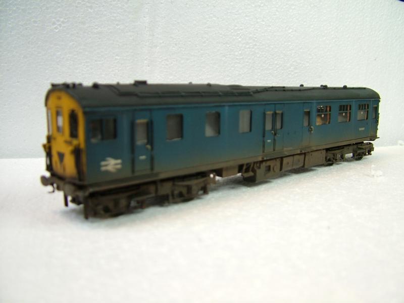
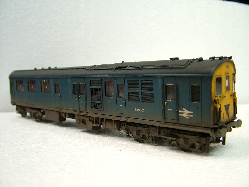
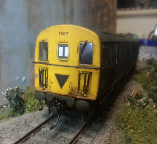
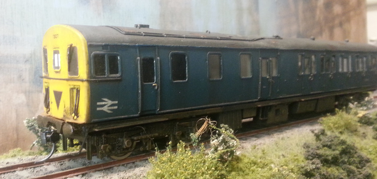
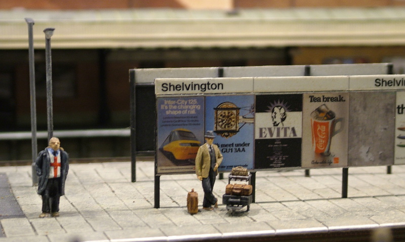
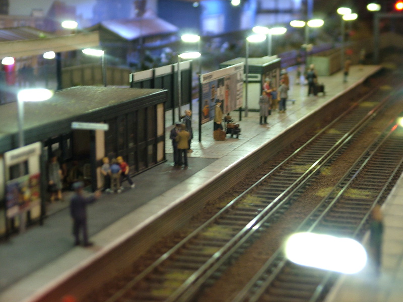
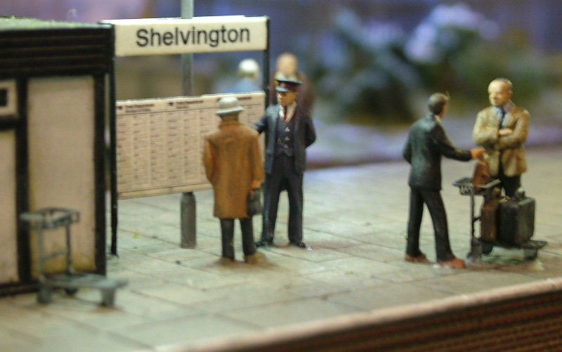
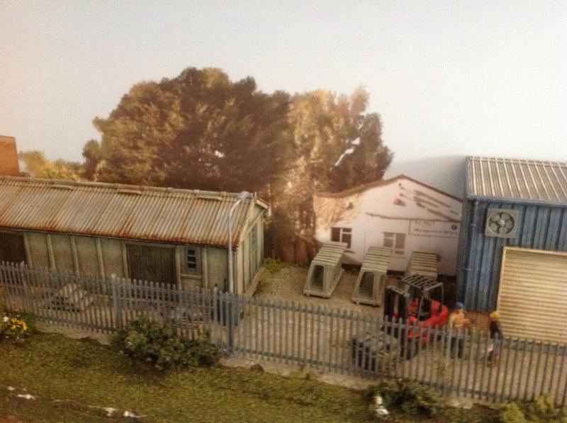
P4 BR Blue Southern Region circa 1975-85 (Fictional what if...)
Sorry this is going all weird. I need Firefox!
 Last edit: by strontium_black

Posted
Full Member
Layout Name - Shelvington
Scale/Gauge - p4Size (length/width/height… not forgetting to include operating space!) -Stage 1 4.7m x .45m with stage 2 6.25 x 3.25 in an 'L' max width .45m
An exhibition layout
End-to end
BR/SR early 1975-85Era/region/location
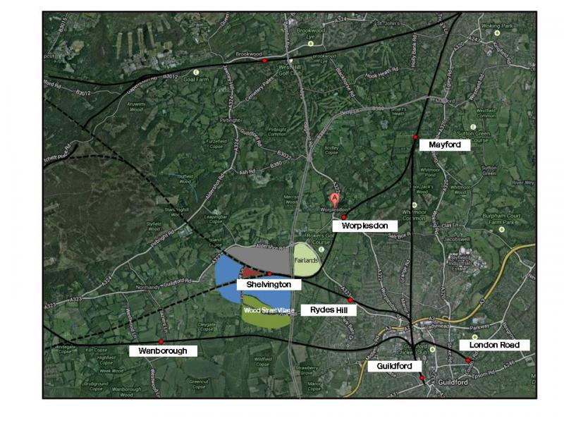
The builders My mum's parents lived in Fairlands, near Guildford and an aunt and uncle lived in Woking. So childhood holidays always involved trips on BIGs and CIGs, REPs and TC's, Tadpoles, Vep's and 33's on West of Englands, the Waterloo and city stock and of course VECs and TISs on the Isle of Wight. So it is my aim to build a layout in the Surrey/Hampshire border somewhere in the Guidlford/Aldershot/Woking triangle. The fictitious history is that the LSWR build a direct line to Farnham off the Portsmouth Direct at Worplesdon, which became a junction station and was renamed Mayford (which it is actually closer to than Worplesdon) the line passed through Worplesdon Village and skirted around the site of the the 1930's Fairlands development before arriving in Shelvington (the layout is going to sit on a shelf in the hobby room!). The line continued on with a station at Normandy, and then under the Guildford -Reading line near Ash. The fictitious line then joined the actual route of the Guildford - Farnham via Tongham line with stations at Ash Green and Tongham, joining the Aldershot -Farnham line at Farnham Junction. Shelvington became an important junction station with the arrival of a secondary line from Guildford.
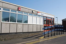
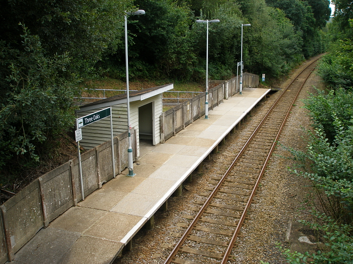
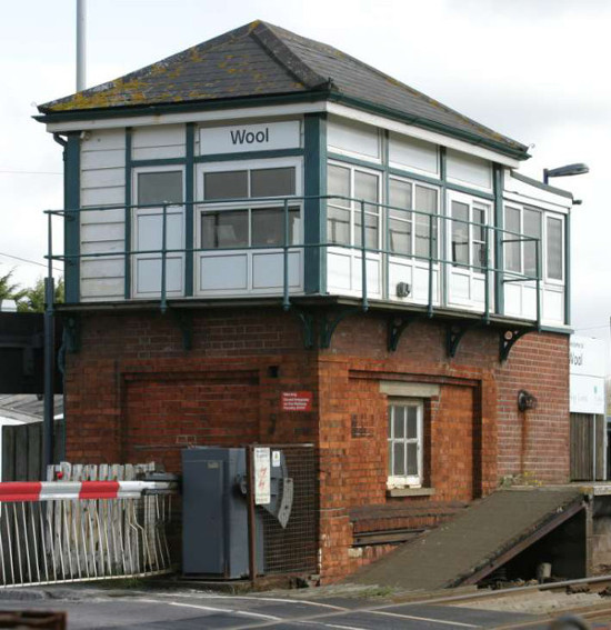
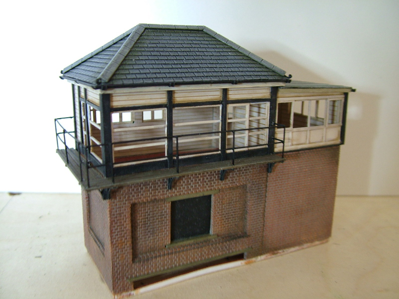
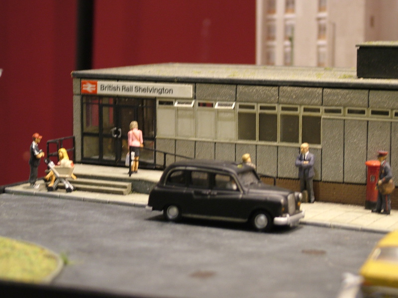
Tired of wranglings with the SECR for joint running over the Reading -Rehill line (actually the LSWR built the Guildford-Ash bit - but that doesn work for my story!) the LSWR built a line which left the Portsmouth direct North of Guildford at the fictitious location of Wooden Bridge Junction (where the A3 passes under the Portsmouth Direct). This line curved around the north west districts of Guildford, passing under the Aldershot Road at Rydes Hill, where the Southern provided a precast conrete halt in the 1930's (inspiration is Three Oaks on the Ashford-Hastings line), before joinging the Worplesdon -Farnham line at a four platform 'V' station at Shelvington. This line continued on to join the LSWR mainline East of Farnborough Main, with a loop back to Ash Vale. Only the line from Mayford Junction to Farnham was electrified by the Southern at the time of the Alton electrification. The attached map gives an idea of my work of fiction!.Dear Mr Beeching saw no value in the the lines continuing west beyond Shelvington, but the Lines east to Woking and Guildford were profitable. Shelvington station was rationalised to just the central platforms forming the 'v', most of the buildings were demolished and a clasp building in the height of 1960's modernism erected (see Wool). Signalling is largely still mechanical (signal box similarly based on Wool), although colour lights have arrived for the platforms which didn't have a signal at the east end. In the early 70's one of the other platforms was rebuilt for the stub half hourly DEMU service to Guildford with every other train going on to Redhill and Tonbridge, two DEMU stabling roads and a refuelling point are also now provided.
Last edit: by strontium_black
Posted
Full Member
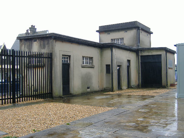
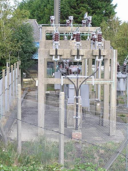
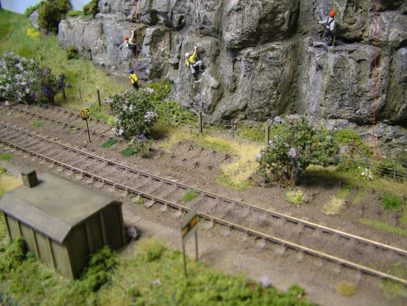
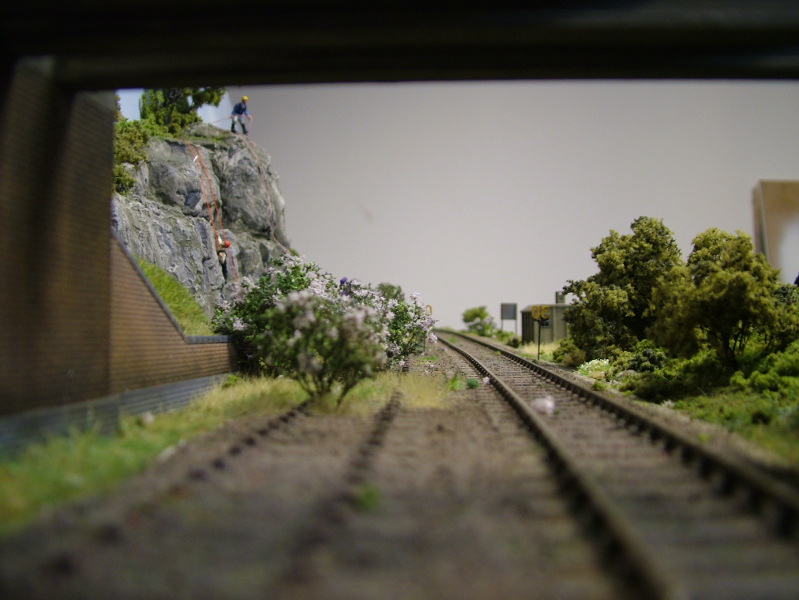
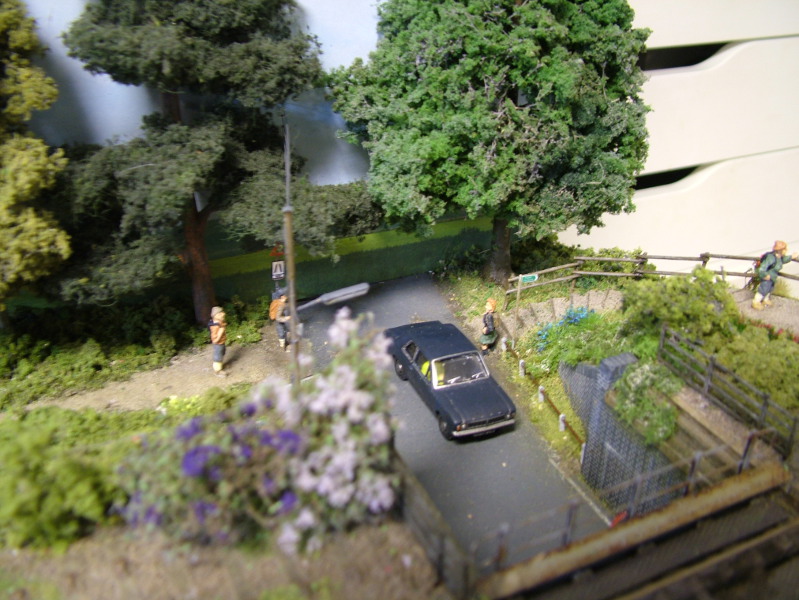
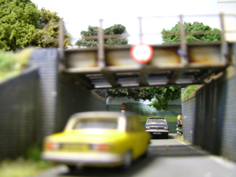
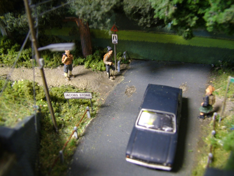
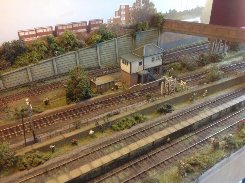
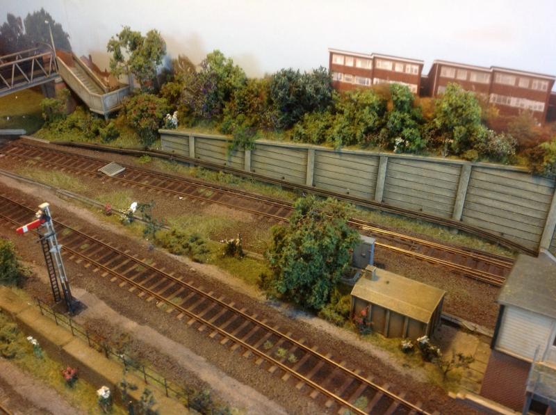
The following is a series of collected pics of the general area and these have been used to draw inspiration for the flavour of the Southern for a fictional place.

Posted
Full Member


Last edit: by strontium_black
Posted
Full Member

Posted
Full Member

Posted
Full Member

Posted
Full Member


Posted
Full Member

Last edit: by Sol
Posted
Full Member
http://www.youtube.com/v/BrXppxfLdSg?version=3
Posted
Full Member
Last edit: by strontium_black
Posted
Full Member
John.
Posted
Full Member
Posted
Full Member
Pete.
it was already on fire when I got here, honest!
Posted
Full Member
Posted

Site staff
Ron
NCE DCC ; 00 scale UK outline.
NCE DCC ; 00 scale UK outline.
Posted

Site staff
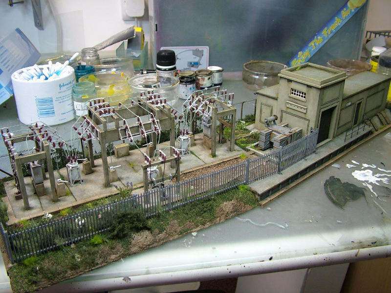
Me too, can you make me one :lol:Very nice Lee & I do like your your power sub-station.
Like the video Lee :thumbs
Must have taken ages to paint all those little people.
Ed
Posted
Full Member
Could you explain how the buildings and platforms were constructed, please?
Terry
Posted

Full Member
Mike
Pig Hill Yard - a small Inglenook shunting layout for my boys, in 00.
Pig Hill Yard - a small Inglenook shunting layout for my boys, in 00.
Posted
Full Member
The tunnell is actually in situ now and that section is almost done scenic wise. We often take take pics as it's being built though so very little to share. Same with building construction i can only speak in general terms.
As I said I build very little the other guy (owner) does I paint everything. I also mentioned a laser cutter was bought last year but this is all before that. He is an engineering type and very precise, also CAD trained. So most stuff that gets built is forst drawn on CAD as a 2D plan. For ease and accuracy this is then printed on label paper and stuck onto plasticard, this then transposes the image exactly as you need to cut it, makes it much easier and more accurate. Being a CAD user we can also create our own etches for things like windows and most of the custom locos include etches.
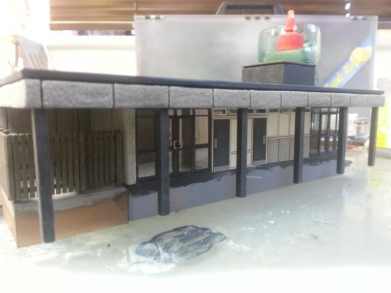
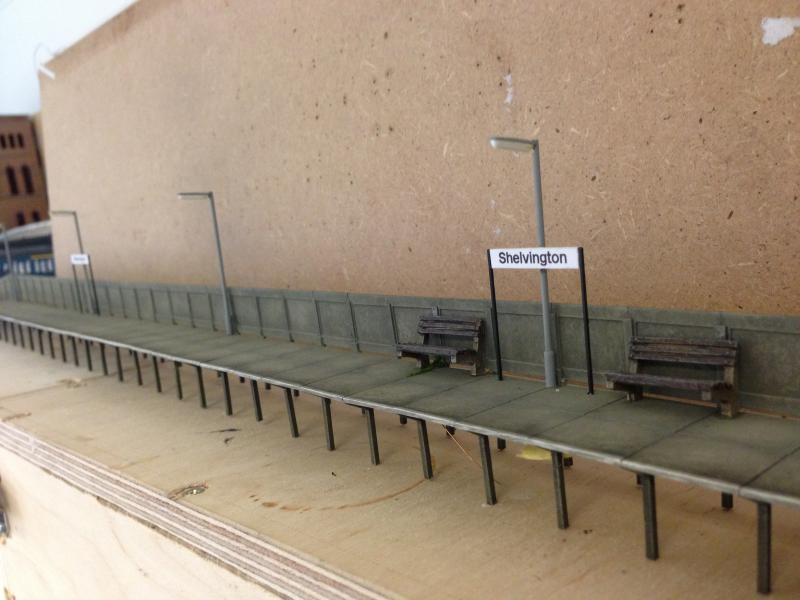
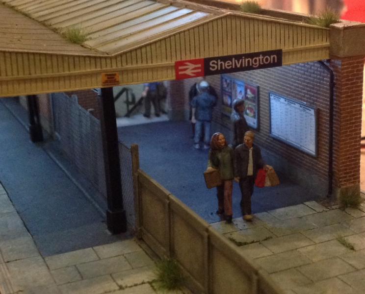
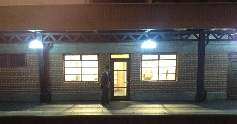
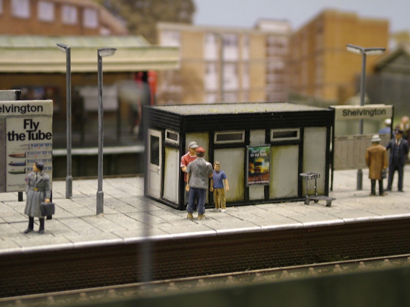
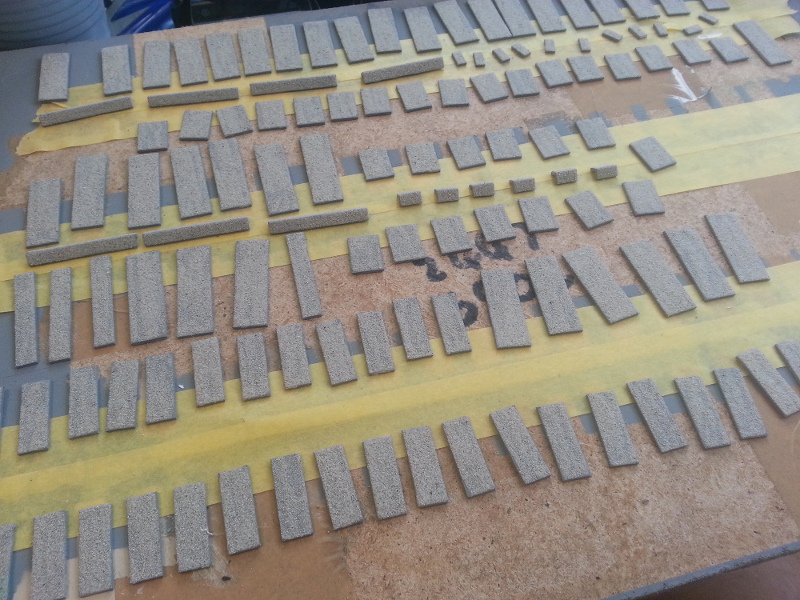
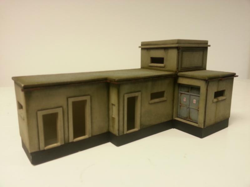
Example1 - the CLASP station. Basically a box was built but was calaculated to be tiled over in the concrete sections which were stuck on after. Below is the little wating room on the platform but just to demonstrate a plasticard box. Microstrip stuck on after to create the paneled look.

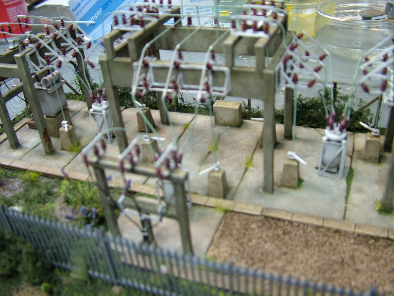
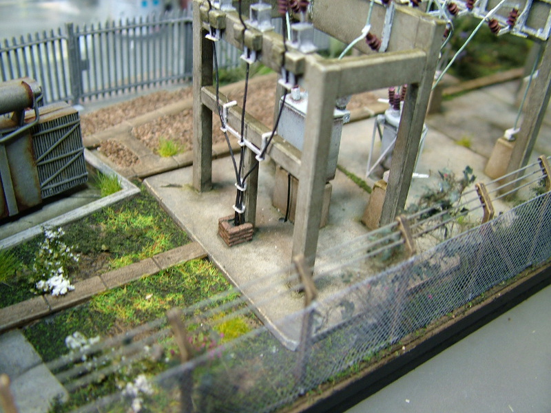
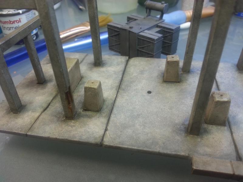
Substation - Exactly the same drawn on CAD, label cut out. Switch farm supports just lengths of plastruct rod. Insulaotors are Sommerfeldt. The white things were scratchbuilt from plasticard then copied in a mould and re-produced as white metal castings. Joining wires just superglued on. Transformer another plasticard build, the fanned bit just many layers of plasticard.


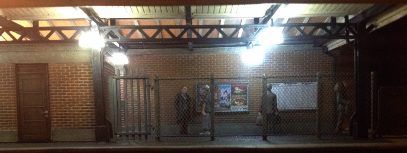
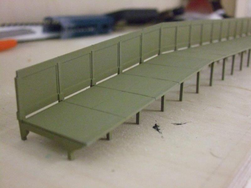
Southern Region Trestle Platform - again another CAD on plasticard drawing. Leg/supports are plasticard master remade as a resin casting BUT there is a small metal rod cast into it so the back piece slots in. If I had pics of that proccess it would make more sense lol.
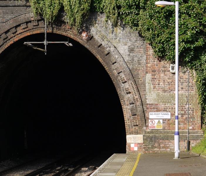
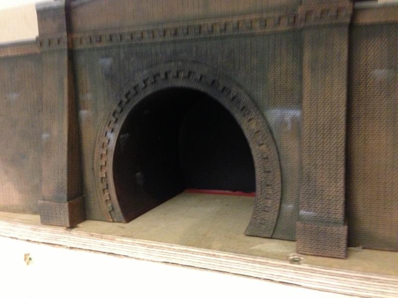
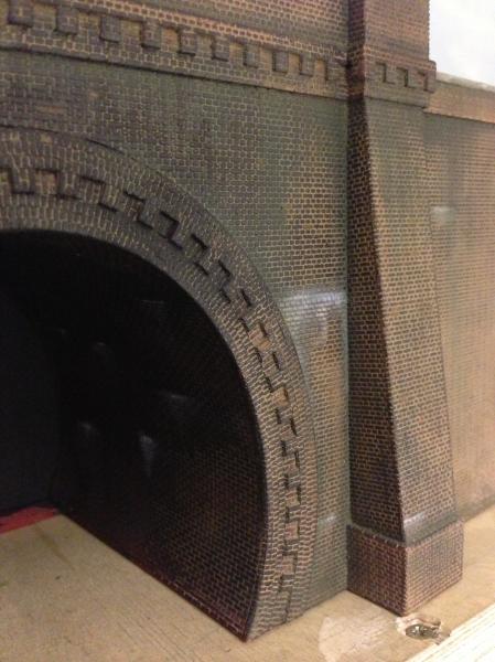
Tunnell mouth - Again drawn on CAD for the odd shape. Not sure how to describe this any further. A 40 thou master overlayed with brick sheets (South Eastern Fine Cast). Castellated section is just more brick sheet with some of the bricks cut out, this is time consuming but can be done. It's very flimsy until it gets stuck on.

This is an early build of the owners house. Made with Wills sheets (don't use them anymore) but a good picture to show how something is made for a new scratchbuilder especially for scale. Look at you own house. How many brick courses from top to bottom, how many that go along the height and width of the windows, how many between the windows?

1 guest and 0 members have just viewed this.