2-way stub turnout
Posted
#235804
(In Topic #13006)

Full Member
Look ma, no points!
Hi all,In my thread on the new layout ("The Back Mill") I mentioned that at least one of the turnouts (points, switches, your choice) was going to be a stub one. These turnouts save some space, and although they have frogs they do not have point blades, but moveable track rails that align with the desired exit lines (hence "stubs"). These are still found on some narrow gauge lines, and were still being used up to the 1970's on standard gauge lines. First time that I have built one of these, so rather than jumping in I decided that a bit of evaluation work (on the KISS principle) was called for.
Much reading has been done over the past few weeks on stub turnout design and modeling approaches. This was accompanied by a lot of head scratching and some "why on earth do that?" moments. The big issue is that in the prototype the two rails are not held in place with chairs or spikes, and are braced with several tie bars to keep the track in gauge. Unless you use live steam or battery power this poses problems as metal bars cannot be used. The obvious method is a copperclad bar. First decision was whether to scratch build or modify an RTR turnout. I have a Shinohara #6, code 100, in HO going spare, so this was used as the guinea pig. What follows is just a quick "look-see" to identify where the problem areas might be.
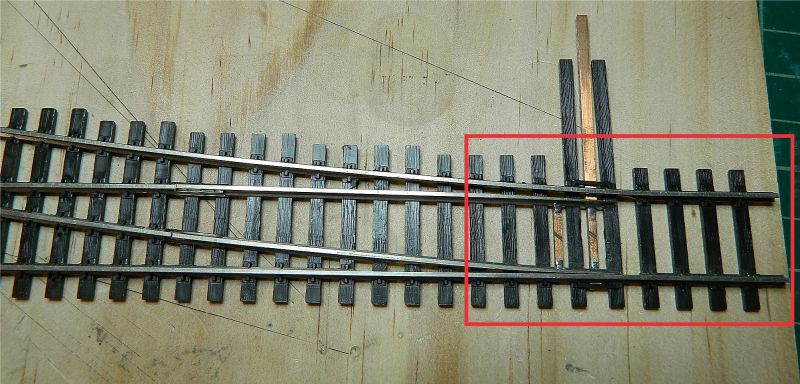
First picture shows the donor turnout, with the section to be removed in red. A copperclad tie (sleeper) was then used to position the cut rails, a code 100 rail gauge fixed the rails, and the rails were attached with a dab of solder.
A section of scrap Atlas code 100 track had 5 ties (sleepers) removed, the rails were cut off, and a rail joiner soldered to each rail. The open part of the rail joiners was opened slightly to give a loose fit, the rails were reattached to the track, and the ends soldered in gauge with a piece of copperclad. A tie bar (intended to be attached to the throw mechanism) recycled from the donor was soldered in place between the 2 copperclad ties. The second photo shows the results, the track slides over the ties to the right, which have had their spikes removed.

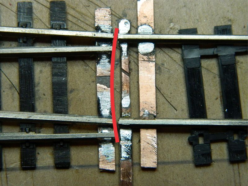
The last photo shows the track moved across to the turnout, the red line shows the arc the rail ends travel through. Note the angle intrinsic to stub designs.
Thoughts so far:
1. The tie bar (and the additional ones not added) are sufficient to maintain the track in gauge. The copperclad tie on the moveable section is not necessary.
2. There is enough lateral movement in the rail joiners to accommodate the small lateral distance required to switch the stubs. Two flexible power droppers will be required, one for each rail. Depending on the rail joiners is not advisable.
3. I could have cut one tie down, and have reduced the gap between the rails.
4 The removal of 7, not 5, ties would reduce the change in track angle when switching the stubs. That said, locomotives and stock moved through smoothly (RP-25 or semi fine-scale profile wheels).
5. The ends of the track on the turnout and moveable section will need to be cut and filed to the arc that the moving rails follow. Pretty obvious really, and not mentioned once in the "how to's" I have read and watched.
6. Cutting the ends off the Micro Engineering turnouts and fabricating the moveable piece of track would be a lot faster than a full scratch build.
7. The first tie bar is normally kept in place with a bridle bar that locates the tie bar and stops it from moving around laterally and vertically. Most modelers use track spikes.
8. Lateral movement needs to be controlled with stops. A small bar soldered to the rail web or copper clad would appear to be the easiest.
9. A Micro Engineering On30 turnout, #5 frog, is only around $22, it matches the On30 track, so game on!
10. I will need some N-scale copperclad ties for the tie bars, order to be placed this week.
The above was a useful exercise, a one hour investment and some spare/scrap pieces identified some areas that I will need to pay attention to, RTR or scratch build. Wonder if I have space for a three-way stub?
Nigel
©Nigel C. Phillips

Posted

Site staff
Ron
NCE DCC ; 00 scale UK outline.
NCE DCC ; 00 scale UK outline.
Posted
Full Member
Hopefully neater than this trial effort!
Nigel
©Nigel C. Phillips
Posted

Full Member
Posted

Full Member
http://yourmodelrailway.net/view_topic.php?id=15028&forum_id=6
(strange I couldn't find the pix in my gallery hence the link)
Cheers MIKE
I'm like my avatar - a local ruin!
I'm like my avatar - a local ruin!
Posted

Site staff
Cheers
Matt
Wasnie me, a big boy did it and ran away
"Why did you volunteer ? I didn't Sir, the other three stepped backwards"
"Why did you volunteer ? I didn't Sir, the other three stepped backwards"
Posted
Full Member
Mike, your topic was the stimulus for looking at a stub. Those frogs are about a #3.5 or #4! The issues once you get into the 3 or 5 stub designs (apart from all that rail bending) are the wiring, and the need for a lot of insulting gaps across the diamonds. If I was doing dead rail battery power with no track wiring I think I would have at least one 3 way into the fiddle yard.
I had another look at the Micro Engineering (ME) #5, the design unfortunately is a bit iffy for conversion. Looks like it will be a scratch build. As luck would have it I found some C+L turnout copper clad that is a good match with the ties on the ME On30 flex track, so I will get cracking. I think a wye rather than a regular turnout might look better.
Nigel
©Nigel C. Phillips
Posted
Full Member
 Last edit: by Dorsetmike
Cheers MIKE
I'm like my avatar - a local ruin!
I'm like my avatar - a local ruin!
Posted
Site staff
Cheers
Matt
Wasnie me, a big boy did it and ran away
"Why did you volunteer ? I didn't Sir, the other three stepped backwards"
"Why did you volunteer ? I didn't Sir, the other three stepped backwards"
Posted
Full Member
Cheers MIKE
I'm like my avatar - a local ruin!
I'm like my avatar - a local ruin!
Posted
Full Member
The images are in the thread, looks like you did a cut and paste from a Google search rather than a download to your image folder.
Nigel
©Nigel C. Phillips
Posted

Full Member
Staying on the thread Kevin.
Posted
Full Member
I have had a few delaminate (out of several thousand), but only if the iron is too hot and left in contact with the copper too long. I use a fine tip iron for this (electric or butane). Also helps if the copper clad is bright and grease-free, some #800 wet and dry followed by a quick wipe with IPA gives a keyed and clean surface. Same for the rail.
Nigel
©Nigel C. Phillips
1 guest and 0 members have just viewed this.