D C C Wiring
Posted

Full Member
Everything live even when using insulated joiners??
Hi Mike I dug out my meter, and the digits were jumping about?? I don't know if the battery needs replacing?? or W H Y .In the meantime I will try it with a battery and buzzer(as it is just to prove a short??) that should prove it. all the best Kevin
Staying on the thread Kevin.

Posted

Full Member
Did you only cut out the wires marked "snip these two wires" in this photo Kevin ?Hi Petermac Now you have got me going?? When I converted the points as per Peco's leaflet.I cut out the fine wires, and chopped off the loose ends, and then soldered a piece of wire between the stock rail and the blade……………………………
If you also cut out those marked in orange where the frog is, that's a problem !!
Using the "bond" wires (shown in yellow) as the droppers as well, is no problem. That's what I do. :thumbs
There's obviously something we can't spot here. Assuming your point isn't faulty (highly unlikely in spite of my earlier comments), if you've done exactly what Mike's shown, it should work………………..:hmm You are sure it's an electro-frog point I suppose …………:roll:

'Petermac
Posted
Full Member
 Last edit: by Passed Driver
Staying on the thread Kevin.
Posted

Legacy Member
Kevin. Make sure the frog wire is not shorting out anywhere… that the bare section is not touching anything metal… I always slip a length of heatshrink on it before connecting it to anything else, using just the last 10mm for a soldered connection…Hi Petermac. Fear Not, "The Long Thin Wire" is intact, and soldered to a length of wire which is in turn soldered to the middle contact of the S P D T Switch (Wire in tube Slide Switch ) which not only throws the point, but, changes the polarity, in one "Fell Swoop ". all the best Kevin
Talking of heatshrink… have you checked all joints to make sure none are touching or shorting out anywhere?
Also… it's not unknown for those slide switches you are using to be faulty… not throwing properly… did you check it before installing? As we're groping in the dark so to speak, maybe worth changing it for another… after checking it works of course…..
Mike
Praise is an excellent fillip for waning ambition.
Praise is an excellent fillip for waning ambition.
Posted
Legacy Member
The following images (again courtesy of Petermac) show how and why you change an electrofrog point for DCC usage… hopefully they are self explanatory and it maybe worth saving them somewhere so you have a reference point for the next time you do one…


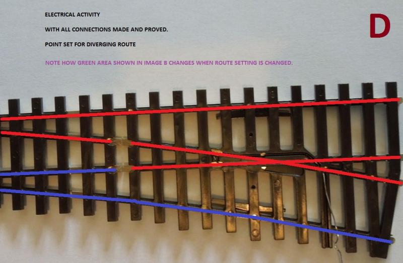
Worth using your circuit tester to check continuity as shown in images C & D with the point set as described… should show if the wiring is amiss somehwere… eg all red lines show a complete circuit and all blue ones do the same…
PS: DON'T FORGET… POWER OFF WHEN USING A CIRCUIT TESTER:
You can't be doing anything drastically wrong as you've got one point working correctly… just a matter of identifying the problem….. Who'd be a troubleshooter eh…
Hope this helps and don't forget to save them…..
Mike
Praise is an excellent fillip for waning ambition.
Praise is an excellent fillip for waning ambition.
Posted
Full Member
UPDATE! I have tried a different approach ?? thinking about it, I wired up a "VERY" short piece of track and set it between two sets of points and it seems to have made it okay, but, like a twit I also dug out another "Y Point" so it is not cut and dry?? all the best Kevin
Last edit: by Passed Driver
Staying on the thread Kevin.
Posted

Site staff
Ron
NCE DCC ; 00 scale UK outline.
NCE DCC ; 00 scale UK outline.
Posted
Site staff
http://www.wiringfordcc.com/switches.htm
INFORMATION #2-17: What is a DCC Friendly Turnout?
Ron
NCE DCC ; 00 scale UK outline.
NCE DCC ; 00 scale UK outline.
Posted
Full Member
Staying on the thread Kevin.
Posted
Site staff
the link I quoted http://www.wiringfordcc.com/switches.htm
shows both the switch & stock rail connected to the bus
Not having seen Gary's plan, I do not know if he showed if the stock rail was also connected to the bus.
Ron
NCE DCC ; 00 scale UK outline.
NCE DCC ; 00 scale UK outline.
Posted
Full Member
Staying on the thread Kevin.
Posted
Site staff
Ron
NCE DCC ; 00 scale UK outline.
NCE DCC ; 00 scale UK outline.
Posted
Site staff
Ron
NCE DCC ; 00 scale UK outline.
NCE DCC ; 00 scale UK outline.
Posted
Site staff
Hi Nigel I think that I have put Firefox on my Laptop?? But, it is the next stage of the operation that I'm not sure about, that is the transfer from Google Chrome apps to Firefox, and I keep getting messages about "It? is not my default browser".. all the best Kevin
Now you have confused me - transferring Google Chrome Apps to Firefox ???
they are independent - but what you can do is transfer all of your website favourites from one browser to another. Firefox when you install it, asks you if you want to bring across favourites from other browsers or read this https://support.mozilla.org/en-US/kb/import-bookmarks-google-chrome
To make Firefox the default browser, under Tools Options General it tells you exactly how to do so
Ron
NCE DCC ; 00 scale UK outline.
NCE DCC ; 00 scale UK outline.
Posted
Full Member
Staying on the thread Kevin.
Posted
Site staff
Ron
NCE DCC ; 00 scale UK outline.
NCE DCC ; 00 scale UK outline.
Posted
Legacy Member
Hi Kevin.Hi Mike Looking at your latest diagram, which is slightly different from the original c/o Gary in Sydney that I had been following??Your diagram shows "Two Wires" one going to the Switch and one going to the Bus.If I fit that additional wire would that cure the Stalling problem?? all the best Kevin
I think possibly the only difference between my diagram and Gary's would be where I attach the dropper to the point… I tend to do one joint incorporating the bonding connection, the lead to the switch and the dropper to the bus… others connect the bus elsewhere
Ruling out any problem(s) with the point Kevin, if you wire it as shown a loco should not stall as it crosses the point. I have 23 electrofrogs on my layout all wired this way… I have no stalling problems.
As an observation;-
This problem is causing you a tremendous amount of hassle and timewasting. Would it not be a wise move to buy a replacement point… wire it as shown and see what happens…
A few years ago I used wire in tube controlled in exactly the same way as you've done… same slide switches etc… only once had a problem when I had a switch not connecting correctly… worked one way but not the other so, also worth trying a new switch…..
Last edit: by 16A
Mike
Praise is an excellent fillip for waning ambition.
Praise is an excellent fillip for waning ambition.
Posted
Full Member
Staying on the thread Kevin.
Posted
Full Member
You will need an electrical feed (track power) to the toe of EVERY point in the row - not just the first ………………:roll:
You will need an IRJ on each and every frog rail………
You will need a method of changing the polarity of the frog on each and every point ……………….
You don't need an extra bit of track between the points - the frog end of one point can happily butt up to the toe end of the next one - and so on for as many points as you care to add. As they butt up, frog end to toe end, you'll see that one rail will have a metal joiner and the other will have an IRJ - that's why you must electrically feed each point separately - the current will pass via the metal joiner to the next point but it will stop at the IRJ, thus leaving that rail electrically dead.
Trying another switch is a good idea - if you've over heated it soldering, it could have damaged the gubbins inside ……….;-)
'Petermac
Posted
Full Member
Staying on the thread Kevin.
1 guest and 0 members have just viewed this.