Keeping baseboard wiring tidy.
Posted
#176235
(In Topic #9967)
Full Member
Keith.
 Last edit: by Keith M

Posted
Guest user
As a "retired sparky " myself, well not retired, I am now employed as a Quantity Surveyor, I am also in the midst of a rather large electrical wiring stage at the moment.
I had thought about trunking but it does not really lend itself to readily to the individual circuits that come from your main circuits or BUS wires if you like.
I also thought about using the telecommunication distribution boxes that you fit out with " Krone " connectors but again this only really keeps the main wiring tidy at the point of connection itself.
I have ended up with loose wiring just tidied up with cable tie's. It does not look pretty at all but I think will be easier when trying to trace individual cables in order to fix the inevitable faults that I have no doubt will occur no matter how careful you are.
It really depends on the individual layout but a maze of mini trunking trying to dodge approximately 60 Cobalt motors was simply not an option for me.
Good old fashioned cable straps I think. Let me know how you get on.
Cheers
Toto
Posted

Banned
I read in another thread of yours regarding 'dcc halfway', which begs me to ask which way are you going with train control, dc or dcc ?? Depending which way you are heading will determine the wiring of the layout. As you are already aware, dc generally runs in blocks or isolated sections, with a lot of paired up wires running to each section, back to the control panel. Dcc on the other hand, the track is 'live' all time, with the individual locomotive decoders and accessory decoders doing the work, running from a 'bus' wire'. Don't believe for one minute that dcc is 'only two wires', no matter what you read !
So really, the wiring comes down to what/how you wish to run your trains and accessories.
I have recently converted to dcc, although running the locos on dcc, but utilising dc to operated points on a seperate controller/panel, via momentary push buttons and solenoid point motors.
Cheers, Gary.
Last edit: by Gary
Posted
Full Member
Definitely does have an element of Bodgit and Scarper about it though.
Last edit: by Bod
Posted
Legacy Member
:thumbs;-):cool:
my webcam link 6.19.184.67:8080
Posted

Full Member

To me, the problem with trunking, as has already been said, is future access to the wires if necessary. :roll::roll:
'Petermac
Posted

Full Member
I use these plus cable ties
http://www.maplin.co.uk/p/small-cable-tie-base-white-100-pack-sj13p
They have an adhesive base, and holes to feed a cable tie through.
Or you could use conduit racking
http://www.maplin.co.uk/p/conduit-racking-25x30mm-cw57m
Paul
Posted

Inactive Member
I use a combination of things. I'm wiring my new board at the minute.
Here's eyes and cable clips. I put masking tape over the cables to hold them in place and then drive in a cable clip.
Except for the figure eight wire powering the SwitchPilots at the bottom, where I drilled the holes for the clip nails.
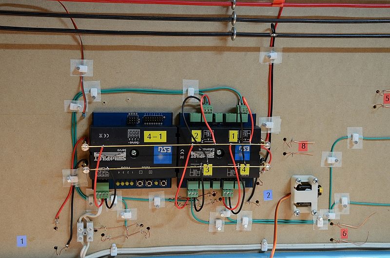
You can see the two main buses above and a smaller bus made from brass wire over the SwitchPilots.
The green wires go to the frogs. If I find a frog is wired back to front, I can simply swap the wires in the green plugs.
Max
Port Elderley
Port Elderley
Posted

Inactive Member
Gary's right that DCC wiring can be done in a very different way to DC; in theory, fewer feed wires are needed because there's no need to create quite so many electrical sections. You also avoid having to switch each section feed or even build a control panel. On the other hand, the basic rules for sectioning and feeding are just the same where pointwork is concerned; DCC power may all come from one pair of wires but the track sections still need isolating and feeding separately to prevent short-circuits. (There are finer details to this but nothing of fundamental importance.)
If Keith wants to keep his options open, I suggest that he wires his layout in the established 'Cab Control' style, enabling normal DC operation. Suppose he has two cabs, A and B, and decides to convert to DCC control. All that's necessary is to connect the DCC system to one of the cabs – let's say Cab A – and throw all his section switches to A. Of course, this is completely reversible and 'friendly' to mates who want to run their DC locos on your tracks.
Friends who are DCC enthusiasts (I sometimes call them zealots) argue (or preach) against this approach but I have found their reasoning doesn't defeat basic electrical theory; I know this is sound because my cab-wired exhibition layout was perfectly happy with either control system for years.
At the risk of crossing swords with any of our DCC members, I think there is also a lot of nonsense spoken about feeding DCC to every length of track, feeding at least every metre, soldering every rail joint etc. This looks like over-engineering to compensate for lack of care and attention in assembling the track. Provided your track joints are clean and tight, voltage drop is not an issue until you get into sections that are, say, ten metres long, and my HO garden layout (in British weather) proved that, too.
Incidentally, my current layout is wired purely for DCC and the control gear itself has given me far more grief than the track.
A sensible-sounding tip offered by one of my DCC zealots is to use a little high-graphite grease on each rail joiner, to exclude muck, reduce oxidation and assist conductivity. Anyone ever tried that?
Last edit: by Ian Wheeler
Anyone who tells you that DCC is simple is a lying b... Er, seriously mistaken.
Posted
Inactive Member
- part of the present layout has electrical conduit screwed to the front of the baseboard; some of the longer wires are kept out of the way inside that; they pass through the back of the conduit to go under the layout
- cable ties on self-adhesive bases are excellent but the adhesive tends to come unstuck from wood; varnishing the wood or pinning down the bases can help
- when I built my exhibition layout, I turned all the baseboards upside down and installed all the essential circuits – colour-coded and numbered – before making any of the track feeds. This enabled me to keep all the wires close to the edges of the board, some of it in conduit. Each board connected to the next via a chunky 18-way connector that I think was designed for the V2 rocket (don't ask how I got them)
- Velcro can be useful; I hot-glued AND stapled the loop part to the underside of the board and held wires in place with short lengths of hook. Velcro comes much cheaper by the roll.
- small screw eyes in strategic places can make very useful wire guides
Anyone who tells you that DCC is simple is a lying b... Er, seriously mistaken.
Posted
Full Member
It would need to be applied carefully though as over-greasing would cause more problems than it solved, I'd imagine.
Keith.
Posted
Inactive Member
I can't see any reason why copper grease shouldn't be as good as graphite although I stress that I haven't tried it. The secret is probably in keeping the stuff off the tops of the rails or any part you intend to paint. Maybe you need an assistant to 'load' each rail joiner with a tiny quantity so that you, as master platelayer, can keep your fingers clean.
Thoughts stray to Electrolube, which comes in a pen-type applicator; this could be applied after rails had been assembled, just by touching the pen to the rail joiner. Even WD40 might work this way…
BUT HOLD IT. This is all theoretical and I suspect that I have had trouble with locos as a result of applying 'conductive' potions to surfaces that rub together and carry current. It may be that clean metal is the only reliable option. Should we discuss this here? House rules may demand a separate topic.
Anyone who tells you that DCC is simple is a lying b... Er, seriously mistaken.
Posted

Inactive Member
So I guess if you are thinking of computer control in the future and if you are thinking that you will use current sensing coils with an RR Cirkits Tower Controller then I would recommend that you avoid bringing a number of power feeds back to a single control panel.
Posted
Inactive Member
Even the XpressNet cables which are effectively bundled, are twisted to obviate spurious effects from inductance.
I also have many anecdotes about having to help people rid themselves of faults due to lazy wiring during the build.
I will share this one with you, though. I was recently at an operating session where the owner of the layout was an experienced modeller of many decades. He is also a retired technician and a soldering super star.
During the session a small piece of track became intermittently open circuited. Eventually he located the fault. A small filler piece of track which had been soldered to its neighbour.
There are many ways to build track work.
There is only one way to build it so that you will never have a fault.
Every piece of track; every rail, stock rail, point rail should be connected by droppers directly to a bus.
If it's a point rail, bond it to the stock rail. If it's a Block (RR&Co), consisting of two pieces of rail, solder droppers to each side of the join and join them under the board and then to the bus.
Never use terminal blocks (chock-block), or suitcase joiners. Solder every joint.
I can't put it more plainly than that.
Max
Port Elderley
Port Elderley
Posted
Legacy Member
:thumbs;-):cool:
my webcam link 6.19.184.67:8080
Posted
Inactive Member
Those who have been following my thread as I build my new RR&Co plank, will see how the bus aids in neatness. As the final phases of the under build take place, you can see how space is at a premium.
http://yourmodelrailway.net/view_topic.php?id=12354&forum_id=21
Once the layout is in the control of the computer, everything has to be 100% reliable. Neatness will help me chase down issues and allows me to get all of the bits into the space available.
Not that there will be any issues.

Max
Port Elderley
Port Elderley
Posted

Site staff
Ian, that concept of not wiring every piece of track, either via bonding or droppers is probably quite satisfactory on a small 8 x4 layout using code 100 rail - normally quite large metal fishplates but relying on then for larger layouts that use use more scale rail like code 40 & 55 combined with locos double heading and sound - more current is drawn and voltage drops via very small fishplates, are not ideal.
At the risk of crossing swords with any of our DCC members, I think there is also a lot of nonsense spoken about feeding DCC to every length of track, feeding at least every metre, soldering every rail joint etc. This looks like over-engineering to compensate for lack of care and attention in assembling the track. Provided your track joints are clean and tight, voltage drop is not an issue until you get into sections that are, say, ten metres long, and my HO garden layout (in British weather) proved that, too.
Then with P4, many use cosmetic fishplates which do basically nothing for power routing so lots of bonding and droppers are required.
Ron
NCE DCC ; 00 scale UK outline.
NCE DCC ; 00 scale UK outline.
Posted
Legacy Member
:thumbs;-):cool:
my webcam link 6.19.184.67:8080
Posted
Inactive Member
Max
Port Elderley
Port Elderley
Posted
Full Member
1 guest and 0 members have just viewed this.