Bluebell Workbench,
Posted
Full Member
Kit Bashing, modifications, kit building.
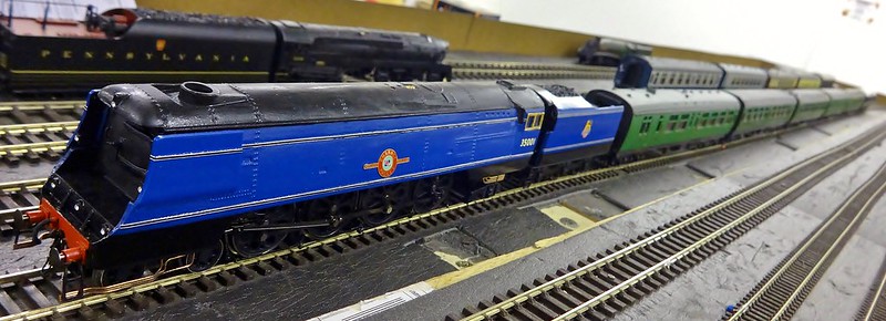
Some unfinished business:These are the finishing touches to the Bulleid 4-8-2, I still had some small bits to do..
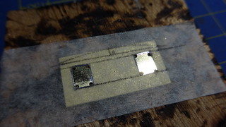
One of these was the brake rigging, I originally brought some RT models brake rigging… sadly my measurements were slightly out, which meant I could use some of it for the first and last set of wheels… so I had to find a solution thankfully, Mainly Trains still had some of their Loco brake rigging etches, which I ordered, and they arrived a few days later…

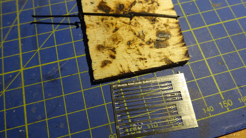
As you can see they were very handy, and were the right sizes to finish the job off… but how to attach them to the brake blocks? I had enough WC plastic brake rigging to use the main mounts which locate in to the brake blocks, I glued the bits of the brake rigging in to the holes on the brakes.
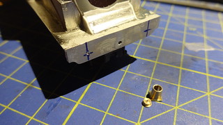
I let the glue go off and dry hard, I then drilled some small holes (0.8mm) in to the blocks that held the plastic rods, I have some small brass rivets, 0.8 x 1mm x 5mm, purchased from prime-miniatures, I soldered these to the brake rigging, and just simply glued them in to position (After painting).
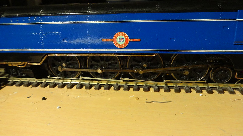
Anyway after a few coats of primer and matt black paint, I finally finished off this area of brake rigging and I was quite happy with how they looked.

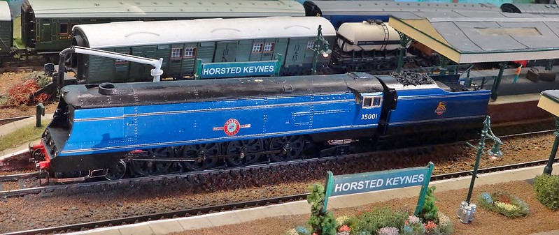
Since these updates the model has still been getting small tweaks to enable it’s maximum performance, It’s run for about 20 hours now, with no problems, a few nights ago, it has now managed to increase it’s max haul from 10 – 20 and can just manage some rather heavy brass kit coaches.
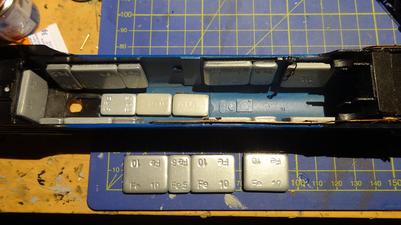
Still a few small tweaks to make, I have added 55grams more weight to the model it had originally for it’s first runs 125 grams of weight… so now it has 180 grams, sadly the springs on the rear aren’t good enough under this weight so these are being hanged to some stiffer ones as the front is pointing upwards by 1 – 2 mm as the rear springs are under load.
This is a picture prior to the additional weight being added:
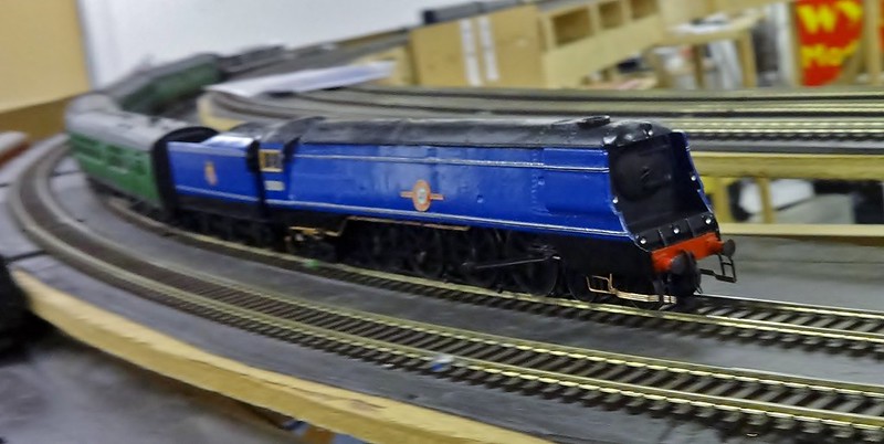
So on the outside pretty much the same, but on the inside and technical bits, it will be much different, but I seem to of started a craze, after much testing up my local club a member has decided to build the second version the 2-8-2…
A small clip on it’s first quite heavy 5 coach train all 5 were brass, weighing about double of a normal mrk1 coach.
https://youtu.be/i3HjGLBzDDM?t=12m43s


Posted
Full Member

 Last edit: by BMR2011
Posted
Full Member
Metropolitan E-Class, Scratch build
Now that most of my Bluebell models have been completed, I have turned my attention to locos that I would like either through seeing them on rail tours, or when I was a little younger at preserved railways.
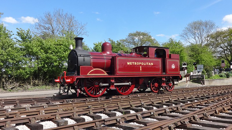
As some of you will know I have 3D printed a set of Metropolitan coaches, the ones that have been run around London over the last couple of years, the 2 main steam locos which were involved was a small prairie L150, and the Metropolitan Railway E-Class from the Buckinghamshire Railway Centre, or better known as Met 1.
There is one kit available a SE Finecast kit…. But you know me, I like to make things difficult for myself, so I decided to scratch build it instead, where’s the fun in building a kit?
I have had this model and loco in mind for a while, I purchased a rather broken Hornby M7 chassis, missing most of it’s bits, no brake hangers, no bogie, basically just 2 driving wheels a metal block and a motor, would be a shame not to use it.
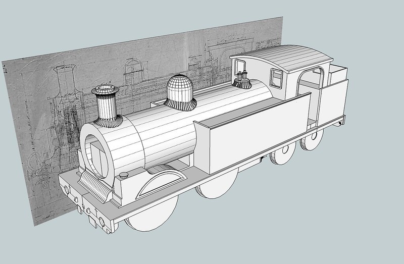
So research began earlier in the year by finding an original engineering drawing for the Metropolitan E-Class on Flickr thanks toe the London Transport museums Flickr feed, this was a good find and gave me a good base to work from and a few just about readable measurements.

With basic measurements length, height, widths ect… this meant I could now start planning out the model and would it work with a Hornby M7 chassis. Usually what I would do at this point is overlay a side profile image of an M7 over the top of the plan above to check it all fits, now with free 3D modelling software tools like Google sketchup it’s quite easy to draw a chassis, and then generally draw an outline of the body.
After seeing that it was possible to do the model then I drew up a plan what I needed, I intend to use only 3D printing for smaller parts of this model, the rest will be scratch built.
The chassis will be a Hornby M7 chassis, which I purchased from a well known auction site, it was quite badly damaged so got it nice and cheap (£20) 3 years ago.
Most of the structure will be made up from Plasticard, mainly 2mm thick for the running plate, 1mm for the tanks / bunker, and this will be reinforced if you like with sheet metal, Brass or nickel. The main boiler barrel will be 20mm diameter so either plastic tube or brass tube will be used with a wall thickness of 1mm.
Some parts will be castings, which adds weight, I was lucky to already build a SEF kit of one of these so have various part numbers / names for castings, so I will be able to order them as spares.
Overall material costs I predict:
Plasticard: £10
Metal sections / sheet: £12
3D printed items: £10
Chassis: £20
Paint / Transfers: £45
Chassis+parts: £30
Posted
Full Member
With materials purchased from various sources
- New Railway Modellers Shop – Plasticard
- Upstairs Downstairs I.O.W – Metal sections / sheet
- Elieen’s Emporium – Brass tube, sheet metal
I could now start the scratch build of this Metropolitan Tank, I don’t do much scratch building these days… so lets see if I still got what it takes.
Having a 3D model on the computer really helps, as it gives me measurements and clearances so I know basically what I am doing how to proceed and also what size
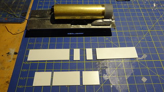
Firstly, I used some 2mm (80/000) plasticard for the base of the running plate, this would be reinforced with nickel silver plate (0.3mm) which will be glued on to the plasticard with Araldite with a 0.3mm overhang on either side as the running plate usually would.
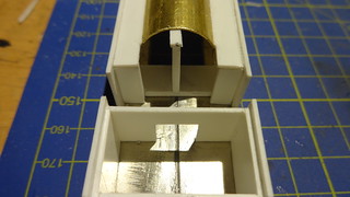
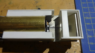
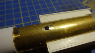
I went ahead and 3D printed the smoke-box from the 3D model I created to get the idea of how it all fits together, I have designed a grove in the rear of the smoke-box to take the brass tube, so it will slot in to the rear, and be glued in place, the underside of the box is to allow the M7 Hornby chassis to fit. The brass tube measures up 20.0mm Diameter x 19.0mm inside diameter x 250mm long purchased from Elieen’s Emporium.
You will need to open up a slot in the underside of the tube, same as the smoke-box end, and then pretty much cut the tube in half around the tanks to allow the motor and electrics to fit. The area behind the splashers also needed opening up so they were not touching the wheels.
A bit of info on the Chassis, the chassis I have had for a number of years, which I picked up from eBay I tend to pick up cheap things that look un-repairable but I usually find a use for it some where. Anyway I brought this Hornby M7 chassis Long framed version for about £20 or so, and now it has a new future not as an M7 the wheel size is slightly bigger by 1 inch at 5ft 7 (22.3mm) than the Metropolitan E-Class 5ft 6 (22mm) Not that we are going to notice the missing 0.3mm… the main thing which picking a chassis is more the spacing and yes getting close to the wheel size as possible. Sadly the bogie that came with the chassis would of been too long anyway so that's gone back in to the spares box.
Overall the chassis needed a few repairs, new brake block set (x9586) and a new keeper plate on the underside (x9581) cost about £10 to get it running again, so the chassis was stripped down, painted as were the wheels, approximately 5mm was removed off the front, and also the chassis was cut at the rear jest behind the motor bracket.

That will do for now, but will continue with a bit more end of the week on the body and chassis.
Posted
Full Member
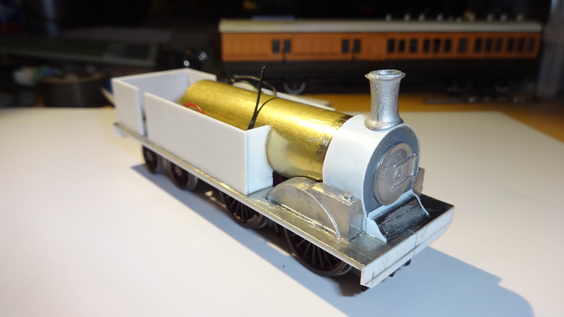
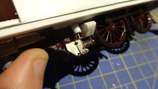
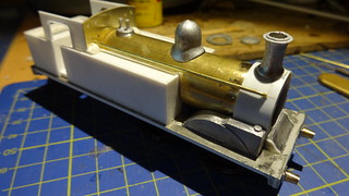
The castings were purchased as spare items from SE Finecast, and are seen loosely fitted to the model. Purchased were: Chimney, Done, Door, Safety Valves, back-head, and tank filler caps.
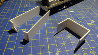
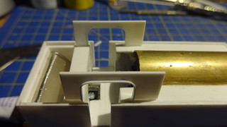
With the main structure now built I can now progress with some internals of the bunker, and mounting for the brass tube at the back head end, again all using 1mm plasticard. Also made is a prop to keep the tube level so a structure can be built up around it. You can also see the bunker taking shape with the slope down to the floor made from off cuts of nickel silver sheet, to keep the weight down on the rear. The bunker was designed as a double wall with the internal wall being 2mm shorter in height for mounting of the shelf at the back of the cab, and also for the bunker extension plates which we will see later.
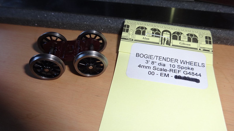
I turned my attention to the bogie at the rear, needing a bogie I rummaged through my spares box and found a spare bogie from one of my Will’s O2 tanks, which have the same axle spacing’s for the bogie of 20mm, with trouble finding 15mm wheels for the bogie (3ft,9) I had to settle for 3ft8 which is about 14.6mm. The wheels came from Mainly trains, and made by Gibson.
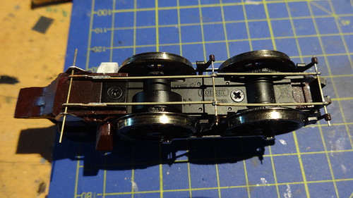
Next issue was to relocate the bogie mounting point, I decided to do something similar to the M7 chassis I had just removed. Using off cuts of the nickel silver sheet, I constructed a bogie mount, this was attached to the underside of the body the plasticard was cut away allowing room for the wheels and also to allow the newly made bogie mount to be soldered on the underside of the running plate.
A hole had to be cut in the topside to allow a screw for adjustments and removal. Holes were also made for electrical wires to pass through to the motor to allow for bogie pickups to be fitted at a later stage.


Back to the chassis… on the chassis, quite a bit of work was needed on the running gear, brakes ect… I used some etched Brake rigging set from Mainly trains (MT186- (Mainly Trains) Loco Brake Rigging & Accessories) but also because the Met tank has different mounting points under the firebox some new mounting points had to be made.
2 addition mounts were created at the rear for the brake rigging to join, this again using off cuts of the metal sheet as above, you can also see I have also replaced a missing sand box just be hind the read driving axle.
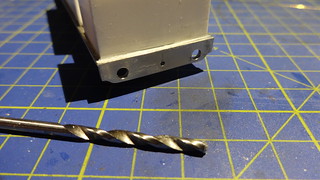
I made a 3mm hole in the bottom of the running plate for the cylinder to apply the brakes, a 0.5mm hole was made to allow the wire enter the cylinder.

That's all for now, more towards the end of the week.
Posted
Full Member
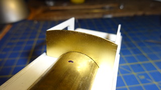
First in the boiler barrel for the dome, 4mm hole and the dome is glue or if you prefer soldered in to place. The safety valves and chimney can be glued on, although at this point in time I still had no real idea of how to attach the body to the chassis which I resolved a bit later on.

For the sprung buffers I shall be using the closest I could find, which were mainly the GWR Collett type buffers which have a slight taper to them.
To fit these you must drill a 3mm hole in the buffer beam, and also solder the ends in to the buffer housing, believe these are made by Gibson
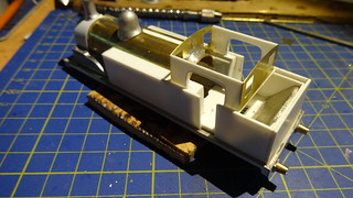
Time was right to start building the cab, I planned out the cab, by images, and plans, using these I managed to create the shape of the cab opening and window openings. The more difficult job was to establish where all the holes were in the front of the cab, for various pipes ect… but I managed to do this using some photos found on Flickr from the previous runs of Steam on the Met.
The sides were made from 1mm plasticard, with some plastic strip to go around the cab opening giving it a slight lip around the edge. The front and rear of the cab I made from the brass sheet purchased from an excellent model shop on the Isle of Wight (UpstairsDownstairs), as I wanted it to be as thin as possible so it didn’t look like the glazing was a mile behind the front face of the cab.
I used tin snips, a small barrel sander, and various drill sizes to make the opening for the windows and pipe work, and using needle files to open up the window opening. The front of the cab was soldered on to the boiler barrel to add to the strength of this area.

1 guest and 0 members have just viewed this.