Scalescenes large station roof
Posted
#169795
(In Topic #9634)

Full Member
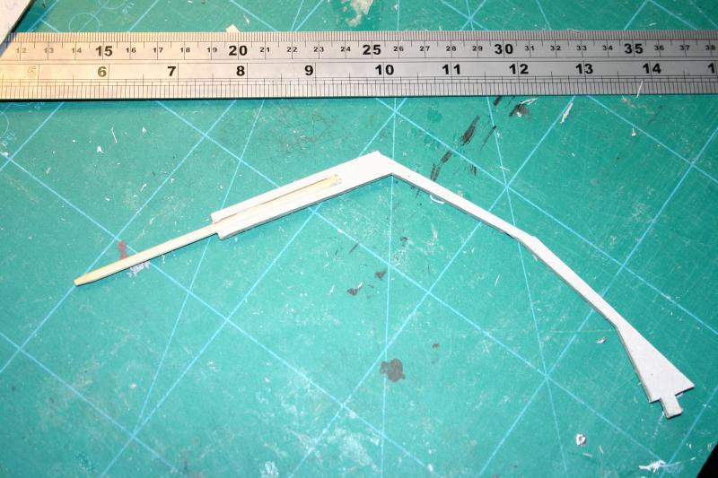
I had the footprint but thought I'd make a start on the roof to be sure the platforms were in the right place.
This will be an "occasional" thread because I'm finishing the third platform at the same time as the roof.
It's taken me over an hour to make one single arch so I shudder to think how long it took you to build your huge roof John. :roll::roll:
It looks like a very nice kit - right up to John Wiffen's usual high standards.
 thumbs
'Petermac

Posted
Full Member

Posted
Full Member
I'll certainly take photos but I can assure you mine won't come close to John's. :oops: I would like to try to make the roof panels removable in sections, if possible. As it is, I think access can only be achieved by lifting the whole structure off the platforms………….:hmm
'Petermac
Posted

Full Member
I think the first arch took me about an hour…….after a while you get in a routine.
Some questions:
Will this be straight or curved? I know at one stage you were thinking of modifying it to be curved…..which is possible but more difficult.
Will you be covering the roof as per John's design or doing as I did and leaving two bays unglazed ?
I did this primarily to improve the view of the interior of the station ……given hindsight I wish I had left a third unglazed
I use the spaces fairly often to insert the hand of god while I am trying to fine tune my stop distances in the bays:oops:
If your tracks are all through tracks the question of access is less important but viewing the interior of the station will be very restricted.
How many sections will the roof contain? They are designed to fit together…….I have 4 in my roof and it is possible to lift it off from time to time…..the problem is where to put it!……..but I have only had to do this two or three times in the last two years.
One final point…….the side walls to which the arches are glued bear all the weight and tend to splay a little………this may be exaggerated in my case because there is, at present only one end ……..I have fixed sub wall on one side and a couple of piles of luggage on the other so when in position on the platforms the side walls of the roof are slightly compressed to fit within them……….hope that makes sense! Incidentally I strengthened the the glazed end with a plastistruc beam
Hope this helps!
Kind Regards
 Last edit: by John Dew
Posted
Full Member
Now Peter you flatter me! (I thought it got one everywhere …
I think the first arch took me about an hour…….after a while you get in a routine.
Some questions:
Will this be straight or curved? I know at one stage you were thinking of modifying it to be curved…..which is possible but more difficult. (It will be a straight terminus John. My curved station is elsewhere)
Will you be covering the roof as per John's design or doing as I did and leaving two bays unglazed ? (I had thought of making the roof panels removable - a sort of "box" structure that "plugs" in between the arches and some cross beams I'm going (planning) to put in)
I did this primarily to improve the view of the interior of the station ……given hindsight I wish I had left a third unglazed
I use the spaces fairly often to insert the hand of god while I am trying to fine tune my stop distances in the bays:oops:
If your tracks are all through tracks the question of access is less important but viewing the interior of the station will be very restricted. (I'm trying to avoid too much viewing restriction by having the option of opening up the whole of each side's glazed panels - in "bay long" sections)
How many sections will the roof contain? (Not sure yet - that's why I need to get the last platform done) They are designed to fit together…….I have 4 in my roof and it is possible to lift it off from time to time…..the problem is where to put it!……..but I have only had to do this two or three times in the last two years.
One final point…….the side walls to which the arches are glued bear all the weight and tend to splay a little………this may be exaggerated in my case because there is, at present only one end ……..I have fixed sub wall on one side and a couple of piles of luggage on the other so when in position on the platforms the side walls of the roof are slightly compressed to fit within them……….hope that makes sense! (It does indeed John so I'm going to see if I can make the "shell" a fixture and remove the panels. I also plan to have spacer beams from arch to arch) Incidentally I strengthened the the glazed end with a plastistruc beam
Hope this helps! (Yes John, it does - as does your very useful "Guinea Pig" thread elsewhere on here. :cheers:cheers)
Kind Regards
'Petermac
Posted
Full Member
Good idea :thumbs I was going to mention tha t:oops: and then thought I would save it for another post as I was listing too many things. I made mine with card and clad them with some of printed stuff from the ends……..plastic might be better[user=434]John Dew[/user] wrote:(It does indeed John so I'm going to see if I can make the "shell" a fixture and remove the panels. I also plan to have spacer beams from arch to arch) Incidentally I strengthened the the glazed end with a plastistruc beam
Removeable glazing ……….nothing like a challenge:roll: I will be watching with interest
:cheers
Posted
Full Member
Watching isn't going to do me much good John - what I need is engineering input ………..………………………………………………
Removeable glazing ……….nothing like a challenge:roll: I will be watching with interest
:cheers
:cheers:cheers:cheers:cheersI haven't, as yet, read the instructions beyond the "arch construction" ……..:oops::oops::oops: so don't really know how the glazing fits.
What I thought I might be able to do is make the glazing panels into little "plug in" upside down "boxes". The glazing is the base of the box and the sides would be constructed from card and this "box", when tipped bottom up (i.e. the glazing uppermost as it should be) would form the "plug". The "socket" would be formed by the arches and my added longitudinal beams between them. A sort of square "bottle stopper".
If I could draw, you'd understand in 2 seconds flat
 Unfortunately, I can't draw ……….:???:
'Petermac
Posted
Full Member
:hmm
I haven't, as yet, read the instructions beyond the "arch construction" ……..:oops::oops::oops: so don't really know how the glazing fits.
Reading thru it is worthwhile!
Having checked downstairs and looked at the photos I now realise you could box the glazing because unlike the roofing its not curved but I dont think it will solve either the viewing or the occasional access
These photos may help
The end two sections are how it is designed
The two sections nearest the camera show my modification so I can admire the station detail and more importantly gently insert a hand without having to move the entire structure (I only did this on the near side…..the window side is fully covered))


Having dug out these photos I am immediately reminded of two things
[1] Predetermine how many sections you will need and print everything out…..unlike me……that way you will avoid the shade mismatch
[2] Each section has its own support wall…..thus there are 4 individual support walls above…..the little pillars hide the join and on the other side a single arch shared by two sections………you can actually see the offset on the first arch (bottom left above) waiting for the final section
This is a major weak spot and the trick if you are doing more than one section (which you are) is to offset the inner wall so you actually laminate the entire wall in one session rather than make 4 individual sections…….I worked this out a bit late but I did the far wall that way and it makes for a far stronger construction
Posted

Banned
I take it you mean something similar to this Peter…??What I thought I might be able to do is make the glazing panels into little "plug in" upside down "boxes". The glazing is the base of the box and the sides would be constructed from card and this "box", when tipped bottom up (i.e. the glazing uppermost as it should be) would form the "plug". The "socket" would be formed by the arches and my added longitudinal beams between them. A sort of square "bottle stopper".
If I could draw, you'd understand in 2 seconds flat

Cheers, Gary.
Posted
Full Member
thumbs:thumbsThat's exactly what I meant but, having looked at Johns latest photos, I think I may have to enlarge the "plug" to encompass a whole bay. As he said, just taking the glazing out would make very little difference to the view. :hmm
'Petermac
Posted

Full Member
No photo's yet !!!
When I get round to building mine, I was intending to fit a camera (probably a raspberry pi-cam) in the roof space looking down on the track ends, so that I see the uncoupling, and the buffer stops. (John - I'm still trying to train my thumb, never mind a PC to stop in the right place).
Raspberry Pi £19 - £27 (depending on model), Pi-Cam £20 capable of 1080p at 30fps, 720p at 60fps
The camera only weighs 3g.
For the walls, I intended to insert bamboo barbeque skewers into each pillar, extending beyond the base an inch or so (probably 2" to allow the skewer to pass through the platform and into the baseboard. The holes in the platform/baseboard being lined with a straw. The straw is a loose fit on the skewer, so should cope with my drilling standards and measuring skills. :roll:
Paul
Posted
Full Member
A pencil sharpener provides the point.
I will also be able to make a jig for the pins to insert into so that all of my arches are the same distance apart at the base.
Paul
Posted
Full Member
thumbs
'Petermac
Posted
Banned
Cheers, Gary.
Posted

Inactive Member
I also have Scalescenes excellent overall station roof kit, but I just couldn't see how it would work with my track layout. In a thread about 3d printing I mentioned that someone was trying to sell me a printer and I have to confess I succumbed.
I'm prototyping the development of a system for constructing platform canopies and station roofs, using my layout needs as the initial driver, with the intention of eventually making the components available on line via Shapeways. Sort of like a grown ups lego with glue instead of the little dots.
Here is picture out of my software showing an indication of how it could go together.
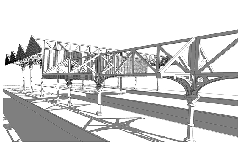
And here is a typical component.

Don't mean to hijack your Scalescenes thread and I hope no one sees this a "commercial plug" because at this time nothing is available for sale. I'm still using a lot of Scalescenes in my station, but hopefully using plastic to do the things I couldn't do with card.
Posted
Full Member
Peter, those canopy supports look great and, at the right price, would sell well IMHO. The Scalelink offerings are excellent but I suspect lack structural strength being a single thin brass etching and are difficult to solder up. The only other real option I've seen is from York Modelmaking - laser cut card, but the price is high if you need a lot of them. That's where 3D comes into it's own - a one off is expensive but, once the design work has been paid for, it's just printer time and resin cost - plus of course, your margin. :cheers
Keep us informed of developments please. :thumbs
'Petermac
Posted
Full Member
Here's a couple of shots showing where it will go:

The last platform will go where the wood block is on the right. The drawn line will be the outer wall. The goods shed (not actually that one but a similar one), was originally closer to the foreground but where it now is, will allow 4 roof sections to be fitted. The track running through the goods shed will therefore, be cut back to where the gap is in the sleepers on that track. The card back in the foreground is where the station concours will start. I plan to kitbash the Scalescenes large station building to fit the available space - probably 2 of their large clock towers rather than just the one but that's for tomorrow……………..:roll::roll:

This shot gives a better perspective of the site. Just between the Class 08 shunter (the yellow square beyond the good shed) and the Lenz hand throttle you can just see, are the coal drops. Access to this "lower" yard is by passing the right hand side of the goods shed - on the extreme edge of the baseboard.
'Petermac
Posted
Inactive Member
Great to see some decent length platforms. What sort of length trains are you planning to run? I was originally intending to run 8 carriage trains, but even though I have a couple of platforms that will accommodate them, other track layout limitations have made me have to settle for six max.
You can get a sneak preview of how things are shaping up at Shapeways here. Model Railway Structures by Wizmacnz - Shapeways Shops
Sorry…it's too late at night for me to code in the hyperlink properly.
Posted
Banned
From what I have read about the amount of weight on the pillars and how they tend to be pushed outwards, would it be wise to have the arches cut from 6mm perspex ?? This then could be laminated with the detailed printed layer. Just a thought ! ;-)
Cheers, Gary.
Posted
Inactive Member
1 guest and 0 members have just viewed this.