Converting Bachmann's Jinty to EM
Posted
Inactive Member
...and upgrading too
:):)What Ho John,I am looking forward to this.It will give me some pointers for my Comet chassis build.
Thanks for shareing.
Derek.

Posted

Full Member
John
John
Posted
Full Member
I wanted to see if the Bachmann motor would work. The shaft is suitable for 1.5mm ID worm gear. The problem I ran into is that the mounting holes are not standard and don't line up with my gearbox.
I actually found a motor/GB that I had done some while ago, so I'll use that. Motor is Mashima can and GB is High level 80/1. This will give reliable slow speed running.
I've said before that these projects are a series of problems to be solved - it seems that nothing is straightforward.
The GB is mounted on the rear axle and, of course, it wouldn't fit the body. I then had to remove the body from the Mazak footplate - a lot of screws! I performed surgery on the footplate to make room - I didn't have to remove a lot of material but Mazak is the very devil to cut!
I also fitted some plates to the front and rear spacers for fixing screws.
Here we are with the chassis and footplate mated:
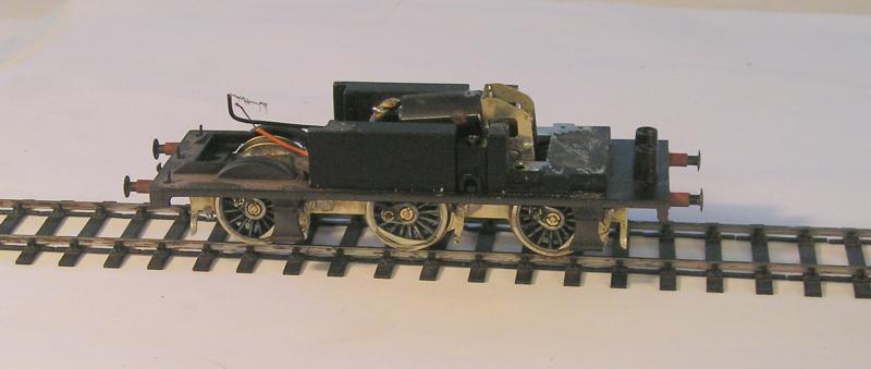
There are still one or two issues. The chassis not as free running with the GB installed as it is without. I can sort that with a bit of reaming. I also noticed there's a foul between the GB and one of spacers - again easy to remedy.
Before you ask, yes, I did a trial fit of the body and it does fit.
John
John
Posted
Inactive Member
Best of luck with this baby John.
Posted
Full Member
So, a bit more progress, the GB holes were reamed in situ with the chassis and now things roll freely. I removed a small amount of material from the spacer so the foul has gone too.
My next task is to get the coupling rods fettled:
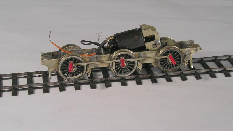
I used wire insulation to hold the rods in place while pushing the chassis along the track. The process is to progressively ream the holes in the rods until the chassis runs freely.
Next, I`ll solder these on, hopefully not solid.
John
John
Posted
Inactive Member
I like that insulated wire idea,
Oh John,What size rivets do you use for the coupling rod join.I need to get some.
Cheers,
Derek.
 Last edit: by shunter1
Posted
Full Member
Here it is after quite a lot of fettling:

Despite getting things rolling freely at the previous stage, I found I still had "rough" or "high" spots. Having soldered the rods together, taking them apart again wasn't on. I therefore removed the wheels, twice I think, and ran a reamer through the bearing holes. This should be done sparingly to get the righty amount of looseness between axle and bearing. Rule of thumb is that the axle, after being positioned in the bearings, should fall out of its' own accord when the chassis is turned over.
After all that, I was fairly happy but there was still the slightest resistance in a couple of places. I then resorted to my jeweller's rouge and oil trick, smearing some of the bearings and rod joints. Running the chassis by hand numerous times on the test track got me to a point that I'm content with.
Not sure what you mean by rivets, there aren't any with this design being laminated from two pieces. The center crank holes overlap which I think you can see below. The Brassmasters design uses a three piece lamination which does require rivets. Eileen's Emporium have rivets.
I have mentioned compensation and thought I'd show what I meant, warts and all:
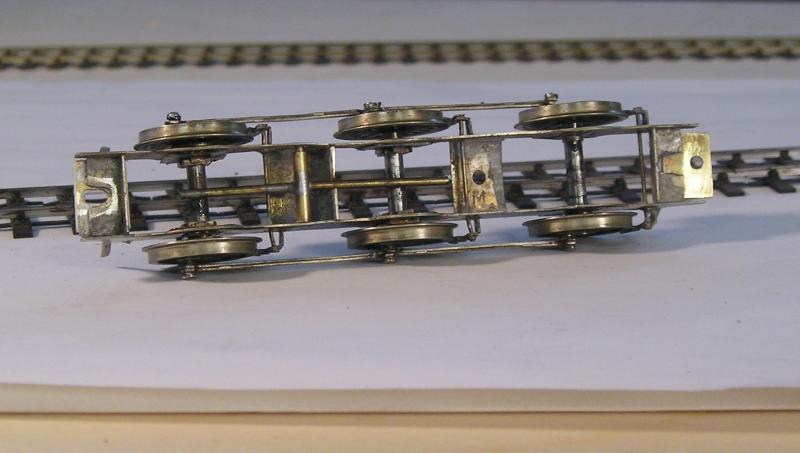
The thing about rigid chassis locos is that if the track isn't perfect, some wheels will lose contact with rail from time to time, reducing electrical pickup. If wheels lose contact, flanges are like to be out of contact too, leading to derailments. 00 wheels have fairly deep flanges which mitigates this slightly.
I don't know when "flexichas" was first proposed by Rod Neep, but it has to be nigh on 40 years now. It's a simple concept and I've used it here.
The idea is to keep all wheels in contact with the rails at all times, no matter how bad the track (I expect there are limits even to this though).
The driven axle, on the right, is kept rigid. The other two axles are arranged with hornblocks and hornguides that are free to travel up and down, meaning that the wheels will tend to follow wonky track. This in itself takes a fair bit of finagling to get the hornblocks sliding freely.
The other feature of the design is the compensating beam which is mounted on a pivot. Each end of the beam rests on top of the axle. This constrains the axles so they rock when necessary.
The design ensures that all wheels remain in contact with track, improving electrical pickup, reducing derailment and helping with haulage.
I've been tinkering with springing but that's for another day.
John
Last edit: by Brossard
John
Posted
Inactive Member
Tell me that compensation beam resting on the axles.How do you counter electrical shorts useing uninsulated wheels on one side.
The rivet I was talking about is for the coupling join allowing the rods to pivot with axle play.
Other question which sliding hornblocks would you use.
cheers,
Derek.
Posted
Full Member
As I said, no rivet in these coupling rods. In post 38 there's a picture of the Brassmaster's rods.
I took a look around at the usual suspects (Comet, Mainly Trains, Markits) and none of them seem to have the hornblocks and guides I use. It's been a while though. Today, I can happily recommend High Level.
John
Last edit: by Brossard
John
Posted
Inactive Member
Cheers,
Derek.
Posted
Full Member
John
John
Posted

Full Member
Cheers
Marty
Posted
Full Member
John
John
Posted
Inactive Member
I was having fun with those Gibson driving wheels of mine.
Finally cracked the problem of them slipping on the axles and losing quartering.Used a knurling tool on my lathe to cut a knurl at the axle ends.The driving wheels are now rock solid on the axles and can take the pressures of loads.
Cheers,
Derek.
Posted
Full Member
Glad to hear you cracked the Gibson wheel problem - a neat solution. It's been suggested to me that rolling the axle on a file will produce a similar result but I didn't try it. I'm still at a stage where I have to remove the wheels multiple times during a build and that isn't good for Gibson stuff.
John
Last edit: by Brossard
John
Posted
Inactive Member
I think Gibsons need drop out hornblocks so one does not have to keep pulling the wheels off the axles.If one can overcome these problems they do have a good range and cost a lot less,Next getting a decent wheel quartering set up organised would save a load of hassle.Useing the Gibson BB tool as its L shaped has given me some idea,s.One crankpin lined up with the rise section the other with the level section should give a good quarter setting.
The Late Guy Williams also recommended fitting a small length of wire into the crankpin screw head slot after fitting to the wheel and useing it to act as a rotation stop so fitting the crankpin nuts did not unscrew the thing.
Difficult to explain in words will show one when I get around to trying it.
Cheers,
Derek.
Posted
Full Member
After my experiments with CSB, I'm of the opinion that even with this, the driven axle should be rigid. This was reinforced by my reading the late Geoff Holt's thoughts on the matter - 7mm to be sure. ( http://britishrailwaybooks.co.uk/books/ISBN/1908763019.php)
My main issue with springing the driven axle is gearbox width because the hornblocks, even the slim ones from High Level, restrict clearance between the EM frames. For 00 such a thing would be impractical I think.
Of course, with CSB, the hornblocks are suspended on a spring wire (the Continuous Springy Beam) so you couldn't get them out.
I've tried the Gibson sprung hornblocks and they are a heck of a fiddle. There are several small parts that have to be soldered together and this was beyond my skills at the time - and may still be.
Brassmasters and Comet have similar systems using coil springs, but getting this set up sounds like a nightmare.
Quite a conundrum.
As for quartering, I have a jig but probably the best way (explained by Tony Wright in his DVD) is to sight through the wheel and line up spokes. Then again, I like Markits which avoids all that. I have Williams' book on scratchbuilding locos - I should dig it out and refresh my memory.
John
John
Posted
Inactive Member
Cheers,
Derek.
Posted
Full Member
John
John
Posted
Full Member
I replaced the front hornblocks yesterday (a slow day because I was waiting for new fridge to be delivered ) and this morning I replaced the rear top hat bearings. To my amazement and delight, the chassis ran sweet when I checked it on my test track.
I hooked up power and performance is quite a bit better than yesterday - think I've cracked it. I spent a little while running in the mechanism. This involved some small application of light oil on the gears and bearings, applying power and holding the chassis on the track with my finger. (You can use a rolling road, but it isn't absolutely necessary.) I ran it at full power for a few minutes, alternating direction every so often. After that, a rinse with lighter fluid - you can tell the running in is working because the fluid that drains off is black with microscopic metal. I repeated the process.
Now to finish off - I hope.
John
John
1 guest and 0 members have just viewed this.