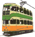
Making trams from card or paper
Posted
Full Member
Trying to upload a photo but no joy.
Gallery shows a place marker but no pic.
Jim
Because, except in some unfortunate circumstances, trains did not run on town centre streets

Posted

Site staff
Regards
Alan
Born beside the mighty GWR.
Alan
Born beside the mighty GWR.
Posted
Full Member
Snag is if no one tells you you can't fix it.
Magic

Jim
Because, except in some unfortunate circumstances, trains did not run on town centre streets
Posted
Full Member
This post has been removed by me as I caught a fatal technical error. I had my drawing prog set for 6 inch DIAMETER circles instead of RADIUS. :oops::oops::oops::oops::oops::oops:.
So I need to redo all the curves. If you have a copy of the deleted posts DO NOT USE IT.
Appologies
Jim
 Last edit: by The Bankie
Because, except in some unfortunate circumstances, trains did not run on town centre streets
Posted

Full Member
Presumably they're "4mm" scale ………………:roll:
'Petermac
Posted
Full Member
The scale is 4mm and the width is 14.5 to allow a 1mm gap each side for wheel flanges. I'm about to do some twin track but have not decided on distance between centres yet as this is street tramway and will differ from railway practice. Either way I hope to get this on the board by this evening.:shock:
Regards
Jim.
Because, except in some unfortunate circumstances, trains did not run on town centre streets
Posted
Full Member
This post has been removed by me as I caught a fatal technical error. I had my drawing prog set for 6 inch DIAMETER circles instead of RADIUS. :oops::oops::oops::oops::oops::oops:.
So I need to redo all the curves. If you have a copy of the deleted posts DO NOT USE IT.
Appologies
Jim
Last edit: by The Bankie
Because, except in some unfortunate circumstances, trains did not run on town centre streets
Posted
Full Member
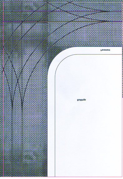
OK! Below is a quarter of a Grand Junction done to the correct radii of 6 inch. This time it's the correct size which is why you only get a quarter and need to print it 4 times and glue it together. The full size is 390 x 570 mm so noway it will print out as a single sheet. I still need to do the mirrored quqrter but that will have to wait till tomorrow.
In fact it will be a bit later as the uploader is having another hissy fit.
Sorry

Jim
Because, except in some unfortunate circumstances, trains did not run on town centre streets
Posted
Full Member
I finally got the gallery to accept my pic by reducing the quality to YEUCH. So if you want to use it you'll need to email me for the PDF where I can put 300.DPI HQ files instead of 50 DPI Low Quality.
Because of the quality I have only shown a quarter of the junction to give an idea of how it will look. You need to use two copies of this one and two copies of a mirror version to make the whole thing. and it comes out as 580 x420 mm. The main road runs top to bottom and has longer approaches than the side street. This is because of limitations imposed by an A4 sheet as I assume not too many people have A3 or A2 printers.
Have fun
Jim
Because, except in some unfortunate circumstances, trains did not run on town centre streets
Posted
Full Member
Merry Christmas to all my readers
http://www.jacquielawson.com/viewcard.asp?code=4437664698242&source=jl999&utm_medium=internal_email&utm_source=pickup&utm_campaign=receivercontent
Normally I would say click on the link for your card but I don't seem to be able to make this into a link so cut and paste it into the browser bar on your search engine for your card
Merry Christmas
Jim
PS
AHA! looks like the board browser did the link automatically.
Last edit: by The Bankie
Because, except in some unfortunate circumstances, trains did not run on town centre streets
Posted
Site staff
Regards
Alan
Born beside the mighty GWR.
Alan
Born beside the mighty GWR.
Posted
Full Member
And as a Scot I also wish you a happy New Year
Because, except in some unfortunate circumstances, trains did not run on town centre streets
Posted
Full Member
Have a good'n.
:cheers:cheers:cheers
'
Posted
Full Member
a card for my friends on the board.
Happy New Year
Jim
http://www.jacquielawson.com/viewcard.asp?code=4592258778242&source=jl999&utm_medium=internal_email&utm_source=pickup&utm_campaign=receivercontent
Because, except in some unfortunate circumstances, trains did not run on town centre streets
Posted
Full Member
Happy new year.:doublethumb Blowing my own trumpet.
I have tidied up a couple of my free web sites.
http://tramweb.yolasite.com is about trams and card bodies.
http://locostmodrail.yolasite.com is about cheap and cheerful train sets - might be of interest.
David
freelance model railways and tramways
index02
index02
Posted
Full Member
Some time back I tried to explain my trolley standard making method and I said that when I next did some I would show you the way I do it.
So here Goes:
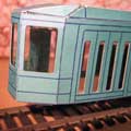
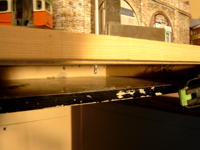
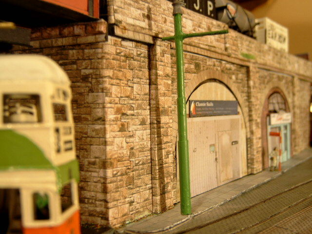
The first picture is where the poles are going to go. This is the back (North) side of Proven Mill.
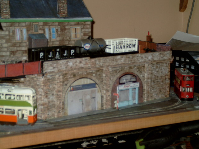
I need about 6 poles but as they will all be made in the same manner I'll just show one until I get the remainder done.
First up are the materials and tools. Two diameters of steel rod and two diameters of aluminium tube.
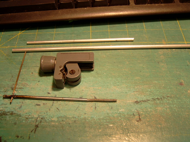
The odd looking lump in the centre is a tube cutter. Identical to the large version used by plumbers etc. It means you get square ends on the tube.
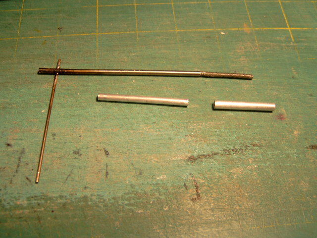
All the components cut and ready for assembly. Remember to de-burr the insides of the tubes as the cutter will create a narrowed opening.
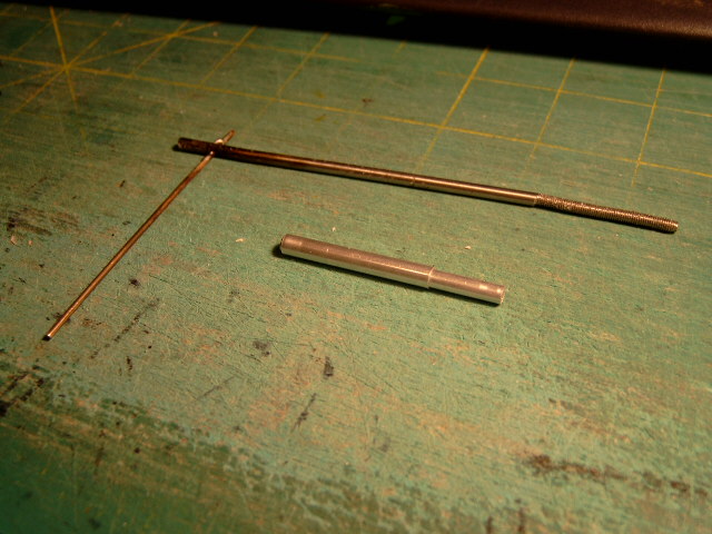
The two tubes ready to slide over the steel centre. The pole is fixed into position unpainted as with the tubes a sliding fit I can lift the outer tube up and paint it without leaving a ring around the base. Then I drop the outer tube down to meet the ground surface (mainly pavement) and paint the entire pole.
The sliding fit means that I can raise and lower the entire pole using an engineers square so that I get the 83mm clearance needed from the roadway to the underside of the suspension arm (80mm clearance to the bottom of the wire ear) and I don't have to worry about uneven roads or pavements.
Hope this has been useful and I'll let you see the results when I have the wiring complete.
Regards
Jim
Because, except in some unfortunate circumstances, trains did not run on town centre streets
Posted
Full Member
Trolley standards part 2:
A hole the correct size has bee drilled in the board and the standard has been pushed through deeper than the desired length. The screw thread on the bottom of the pole was put there when I first tried to make poles so that with a nut and washer above and below the baseboard I could raise and lower the pole to get an exact height. Works like a charm but you then end up having to fit the pavement over or round the poles and recess everything so that the upper nut and washer are covered. Since I did a job lot of them I still have a few to use up.
Now I simply push the pole through the board deeper than the desired height , coat it with quick setting epoxy, the screw thread makes a wonderful key for it, and pull back up to the desired height and leave it to set.
Next stage is to paint the bottom of the widest sleeve, and push that flush with the pavement. Paint the rest of the standard and put on the finial. The finial is an air rifle pellet. Too big really but all I have at present. The box of pellets is also a handy weight to keep things in place when building.
The paint also acts as a glue and fixes the two sliding tube in position.
The screwed portion of the standard covered in epoxy and ready to be pulled into position. You CAN push it but it is STICKY.
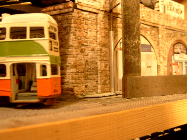
Standard in position. You can just about make out the scribe mark on the square marking the underside of the span arm.
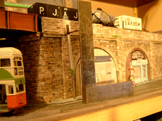
Both sleeves raised up and the base of the outer sleeve painted
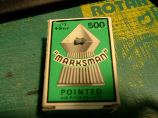
The finial and my supply of spare finials. Do not attempt to use them as airgun pellets as they are NOT the best on the market.
Painted and with the finial sitting on top waiting for the adhesive (the paint) to dry so I can paint that as well.
Hope this is of use
Jim
Because, except in some unfortunate circumstances, trains did not run on town centre streets
Posted
Full Member
Do the aluminium "outer" sleeves remain as "sliders" (except for the paint bond) or do you also glue them in place and is the span arm steel or brass ? If steel, is it soldered/welded to the steel inner rod ?
I can't remember if these were to be carrying power ……..:roll::roll: If so, how do you connect them to the wire feeds ?
I plan to use a similar idea but had originally intended to use brass rather than the steel/aluminium hybrid - mainly for ease of soldering but brass rod isn't as strong as steel ………………………:hmm
It will be interesting to see how you do the actual overheads next. :roll:
There was an interesting little article on "OO" Gauge traction poles in the latest TLRS magazine which gave the scale diameters of the various "parts" making up the pole.
'Petermac
Posted
Full Member
Not certain about a "How to" it's just how I do it. :hmmOthers will come up with variations of this and good for them. For example, if I owned a lathe the poles would be turned up including a finial.
OK in order of asking:
Since the "sliders" have no structural function the paint is all that holds them in place. Other than adding another stage to the construction there is no reason why they should not be epoxied into position.:)
These will not be the power feeds but since they are steel and have the overhead wire ears and hangers soldered on they will almost certainly have power to them. With those having screw cut bases I could attach the feed that way.:???:
I intend to run the positive feed up thicker (house mains) wire attached to the poles and out to the overhead itself. There will be a section isolator box next to the pole as per prototype practice. In this case the positive will be "common" and section isolation joints on the twin return through the rails. The overhead will already be out of scale so anything that removes overlarge joints is worth doing.:)
The Span Arms are soldered INTO the span pole. I drill the pole on a pillar drill and being held in a drill clamp. A little off centre does not matter and if you do not have the tools filing the two components until they fit.
I solder but epoxy also works.
A useful trick I have learned is that that as there are different melting point solders I use electricians solder on the Span pole/Span arm joint, 180deg melt on the hangers and 70deg melt on the ears. This lessens the chances of de-soldering the joints as you work along the pole. I have used epoxy for the first joint. There is nothing exact about the melting points of the solder these just happened to be the ones the local shop had in stock.:thumbs
I will need to make the isolator boxes with a recessed base so that I do not weaken the baseboard around the pole and can bring the power feed up as far away from the pole as I can. It may be possible to drill a hole nearer to the Traction standard then fill it with epoxy but I would rather leave a few mm Between the holes.
Hope this clears up the points you asked.
Regards
Jim
Last edit: by The Bankie
Because, except in some unfortunate circumstances, trains did not run on town centre streets
Posted
Full Member
You asked about power to the overhead.
I have one picture in my collection. I have no Idea where it came from, but I have had it since the 1970s and if it is in someones catalog I apologise but It is being used for illustration only and is not intended to breach any copyright.
It illustrates everything about the Glasgow overhead and a fair bit about tram /bus stops. Have a look below.The original may have had some heavy handed retouching but I'm not certain.
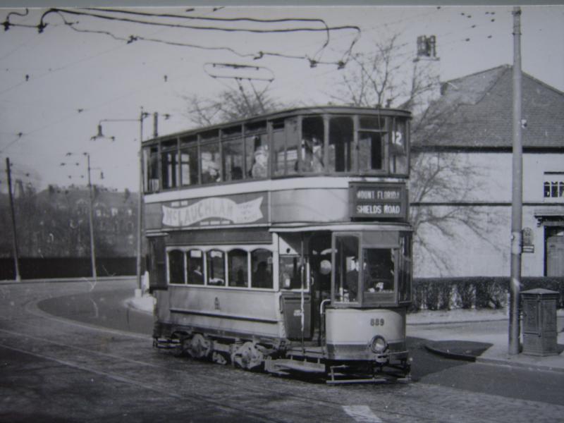
At the right hand edge there is a tram/bus stop showing the different type of stops and the white band where the stop sign itself is fitted. Next to the trolley standard being used as the stop sign pole is a section isolator box. Presumably the box is for the return via the rails as there is no connecting cable to the overhead. That can be seen coming in from the upper left hand edge over the power conductor.
Regards
Jim
Because, except in some unfortunate circumstances, trains did not run on town centre streets
1 guest and 0 members have just viewed this.