Shelf Layout
Posted

Full Member
And I hope things have improved since those days Geoff ………………:roll::roll:………………………………………………………………………….I was never categorised as a "completer/finisher". ……………….

'Petermac

Posted

Inactive Member
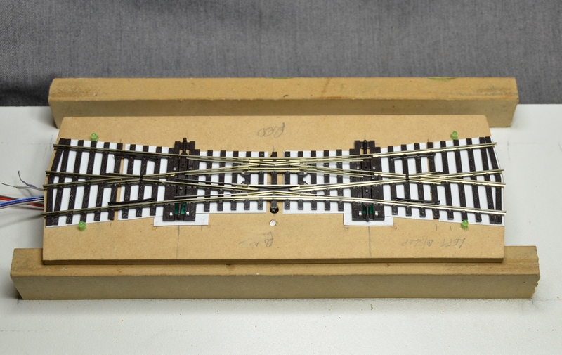
There is .5 mm styrene under the turnout, right across to keep it level with the fillers under the throw bars.
The switches had to be installed after the turnouts were mounted.
The white globules are PVA as before.
It's important to remember that the switches are changing the polarity of the frogs furthest from them - as are the switches for the LEDs operating the LEDs furthest from them.
The unit has been tested and is working correctly. Five hours work.
Max
Port Elderley
Port Elderley
Posted
Full Member
Everytime I wire a double slip, which to be honest, isn't that often, it takes a good few minutes head scratching and experimenting to work out the wiring and which way round to throw which switch for which route.
Posted
Inactive Member
Max
Port Elderley
Port Elderley
Posted
Full Member
 Last edit: by Geoff R
Posted
Inactive Member
Max
Port Elderley
Port Elderley
Posted
Inactive Member
20% improvement. 4 hours.
Max
Port Elderley
Port Elderley
Posted

Banned
Cheers, Gary.
Posted
Inactive Member
Max
Port Elderley
Port Elderley
Posted
Full Member
here I am just about convinced myself to go DCC and you stick that on the page saying it only took 4 hours this time.
would you care to have a crack at a show and tell for Nuclear Fission or something.
Thank goodness I've managed to only need one. :???: so neat, so neat
Kevan
Posted
Inactive Member
Max
Port Elderley
Port Elderley
Posted

Full Member
I have yet to bite the bullet and take one of my N gauge turnouts to task and wire up the frogs for switching. They are so blanking small.
I currently have 15 on my layout and have very little trouble with them, an 57xx or a 14xx will stall at very slow speeds but that's about it. I never seem to get the wheels shorting out the closure and side rails either.
To me, it seems like a lot of bother and additional expense to switch the frogs.
Can you suggest the benefits of doing so… Would the short wheelbase locos no longer stall?
Cheers
Marty
Posted
Inactive Member
My boxcars all have decoders which operate the couplers, so in theory I can uncouple them while they are sitting on a turnout.
None of the above makes any real sense, I know. It's like asking me why I'm fitting 32 Block detectors for RailRoad & Co.
More showing off, I guess.
When I was retrenched I went from a challenging engineering job to a not-very-challenging-job. I find this hobby stretches me and keeps the leetle grey cells from shrinking.
Well, that's my excuse - and I'm sticking to it.
Max
Port Elderley
Port Elderley
Posted

Full Member
Getting back to Marty's question though, the main advantage is that you no longer have to rely on getting a good electrical contact between the point blade and the stock rail. This is, after all, just a touching surface contact and if either of the surfaces is dirty, there is a chance that the frog will actually end up completely dead. The more likely scenario, particularly if you're using DCC, is that the DCC signal will become corrupted and you lose control of the loco. By fitting a separate power supply lead to the frog you completely eliminate any reliance on the blade/stock rail connection and you're always sure of having the frog set to the correct polarity and the DCC signal being 'clean'.
Back to you Max.
Last edit: by Chinahand
Regards,
Trevor
Trevor
Posted
Full Member
Sorry Max, one more…
The majority of my point motors are seep and are wired up in preparation for frog switching, just haven't tried to put the wires on the turnouts yet. It means some horrible gymnastics under the base board… Which is why I'm following this thread with interest.
Do electro frogs require the contact between switch and stock rails to maintain current?
I'm DC too BTW.
Last edit: by Marty
Posted
Full Member
Thanks Max and Trevor,
Do electro frogs require the contact between switch and stock rails to maintain current?
I'm DC too BTW.
Hi again Marty.
No. the power to, and polarity of the frog is completely independant of the contact between the baldes and stock rails.
Regards,
Trevor
Trevor
Posted

Full Member

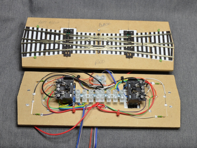
and here is a jig for centering them during wiring
As has already been said, the switch on the left hand motor change the polarity on the right-hand frog and vice-versa.
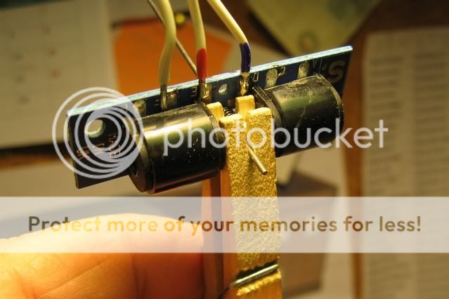
and—
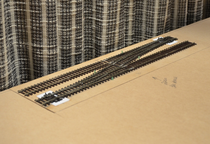
After a great deal of frustration with the switching for the double slip …. I think I have hit on an unlikely work round for the D/slip as follows.The average Peco turnout moves sufficiently far to allow a Seep motor to switch successfully, i.e. there is enough travel for the sprung wiper to travel between the two points indicated by the arrows below.The double slip permits barely half the distance of travel and thus the wiper on the switch arm only just makes contact with the appropriate contact. By allowing the motor to move beneath the board by an extra fraction of a millimetre, better contact is assured, and 100/100 good contacts were achieved.If you are having contact problems with Seeps, I'd suggest backing off the mounting screws a little.N.B. This only improves matters if you are operating them electrically, should you have to move them 'handraulically' from above then it won't help.
Sorry about the hijack, Max,
Doug
Last edit: by Chubber
'You may share the labours of the great, but you will not share the spoil…' Aesop's Fables
"Beer is proof that God loves us and wants us to be happy" - Benjamin Franklin
In the land of the slap-dash and implausible, mediocrity is king
"Beer is proof that God loves us and wants us to be happy" - Benjamin Franklin
In the land of the slap-dash and implausible, mediocrity is king
Posted
Full Member
Another possibility which occurs to me is to file the contact washers to a slightly oval shape or even just make them slighly smaller overall. Hmm. Will have to give this more thought.
Regards,
Trevor
Trevor
Posted
Inactive Member
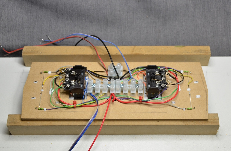
Wiring turnouts is in two parts. Powering the motors and switching the frogs.
I don't have a problem driving the solenoids as I'm using the DCC Concepts AD-S8 units. These combine a capacitor discharge unit (CDU), with a decoder. They are mounted on a board in gangs of 8, which works out well as I have 16 turnout motors on the layout. The S8 needs no power supply (unlike the LS 150 I used last time), and is connected directly to the DCC track bus.
So, it comes down to wiring the PL 15 DPDT switches to switch the frogs. It isn't vital to switch the frogs as Sol has "dead" frogs on his layout. All of his locos are long enough to span the frogs, but 0 6 0 and 0 4 0 locos often can't reach across the unpowered frog rails, so if he had any of those it would be different.
The moving rails are powered through the pivots, so there is no need to worry. The droppers are soldered to the rails in the gap underneath and the pivots are part of those rails. I'm going to do a more detailed thread on the finer points of the builds (when I get a round tuit ;-) ).
The LEDs are just a help for programming in RR&Co. So I'm only using half of the PL 15 (SPDT).
Switching the frogs for a double slip is just a matter of getting your head around it. The switch on the motor operates the frog at the opposite side of the turnout. As with a standard turnout, the moving contact in the switch is connected to the frog and the outside contacts are connected to the rails.
Never worry about hijacking my threads as it makes them more interesting to read later on. I'm the worst offender at hijacking, so I can't say anything. :roll:
Max
Port Elderley
Port Elderley
Posted
Inactive Member
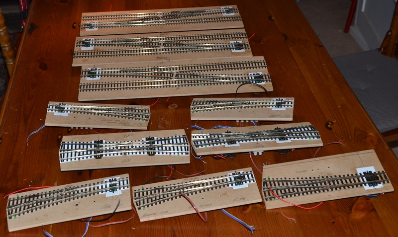
They're all done!
Now to make the first pit . . .
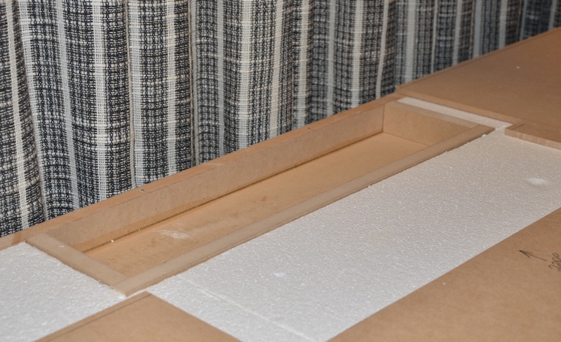
The styrene is cut away and 30 mm walls are introduced.

The module is test fitted.
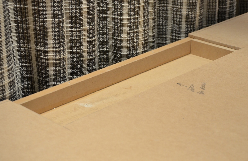
The top sheet of 6 mm MDF is slid into position.
. . . and the module is dropped into place.
It doesn't look like a great fit, but it's all just sitting there. Once the screws go in, it should all sit down flat. :roll:
Hopefully that will make it clearer.
Max
Port Elderley
Port Elderley
1 guest and 0 members have just viewed this.