John's Workbench
Posted

Full Member
Some recent projects
Today's progress so far has been detailing the underframe.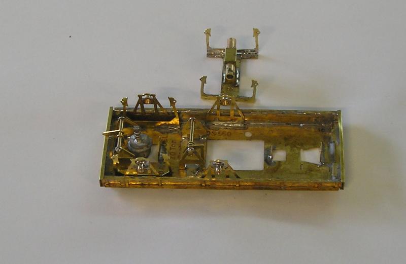
I've made up the center axle assembly. The wheel axle sits in the tube and has it's pinpoints ground off. A wire will pass through the center of the assy and the rightmost rocking axle assy to float. I haven't quite got that straight in my head yet.
I also made up the brake cylinder assembly and, to it's right, the V hanger assy. The instructions say that the 6 wheel brake gear is "quite complicated" but pictures are provided so we'll have a bash at that.
John
John

Posted
Full Member

Lower stepboards are on as well as axlebox/springs and buffers. You may notice that the cylinder looks different. That's because just after I took the last picture, I washed it. In doing so I dropped the thing into the sink and the cylinder came off and vanished down the plug 'ole. I wasn't about to fish around in the U bend so I used a spare. (Aside: Mainly Trains carry a large range of useful bits and pieces under their own brand name - always good to stock up on such things).
I'll paint it next I think since once the brake gear is in and wheels installed, there is little access.
John
John
Posted
Inactive Member
I assume by floating axle they mean unsprung it just rocks with the track undulations?
Those sinks are a menace. Mainly trains do stock some useful stuff.Also they are very reliable suppliers for us mail order people.
I still have some comet loco chassis in jiffy bags plus motors and gear boxes.
Have a good week.
Derek.
Posted
Full Member
This morning I finished off the body by preparing handrails and soldering the whitemetal ends.
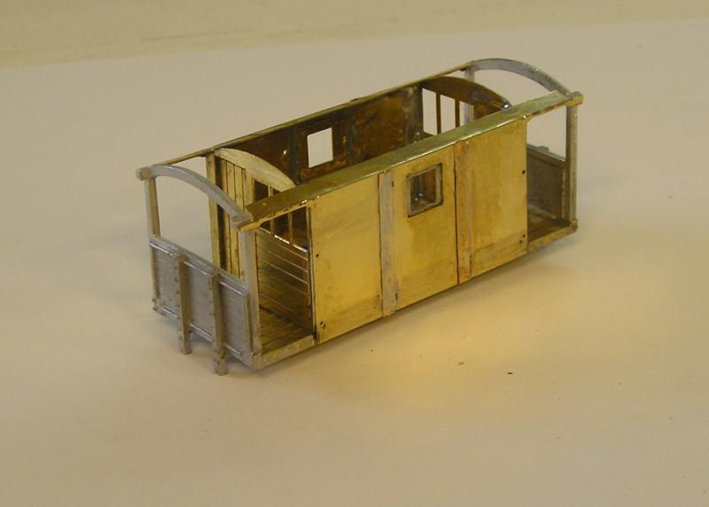
All was not sweetness and light and had to rip the thing apart last night when I realized that side flanges had to be angled and that the sides had been put on too high. All good now though.
I also revisited the underframe to see what I'd forgotten. Sure enough I had left off some upper footsteps so had to scrape off the primer to get those on. Also glued on the reservoir.
I also found two pieces associated with the brake gear that are missing from the drawing so I don't know where they go except that from the cryptic instructions they are near the center axle.
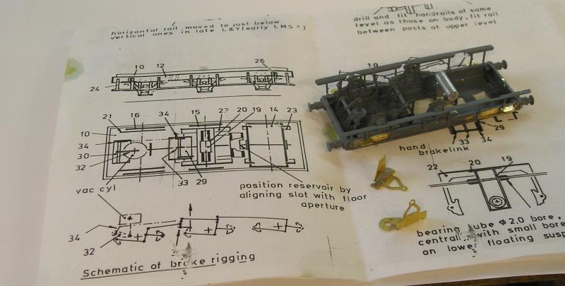
The errant pieces are the separate brass bits.
So, tooth sucking and navel gazing until I figure out what to do next.
John
John
Posted

Full Member
You've got to be really, really pleased with that coaching stock - it looks wonderful. A real labour of love but it was all well worth it :pathead:pathead
Regarding the brake van - I'm ashamed to admit that I've never built either a brass or a white metal kit (although I have melted a couple of the latter before now :oops:) but I'm wondering how you solder white metal to brass given the, presumably large, difference in temperatures between the two materials required to get the solder to bond. :hmm
'Petermac
Posted
Full Member
I'm particularly happy to have finished the coaches, they came out well, and the chap I built them for is over the moon. I was able to take them much farther than I thought.
No need to be ashamed about not building a brass kit before - I haven't done all that many myself. We all need to find our comfort zone. The nice thing about brass is that you can't melt it and if you make a mistake, you have a do-over.
One goal I have is to try to show people that there is no magic to these kits, certainly not if I can do them.:mrgreen:
Good question about whitemetal and brass. Low melt solder (70C) will not stick to brass, but it will stick to 145C solder. Therefore the trick is to tin the brass with 145C and then use 70C solder (not really solder I'm told) to attach the whitemetal parts. I will solder large pieces but for small ones I use cyano.
I'm really liking my soldering station, it responds to temperature adjustment quickly.:Happy I'm using paste flux and this is doing a great job vs. phosphoric acid.
See my other thread on the Cauliflower for more pontificating.
John
John
Posted

Full Member
I'm just catching up after a long lay-off John. ;-)
You've got to be really, really pleased with that coaching stock - it looks wonderful. A real labour of love but it was all well worth it :pathead:pathead
Regarding the brake van - I'm ashamed to admit that I've never built either a brass or a white metal kit (although I have melted a couple of the latter before now :oops:) but I'm wondering how you solder white metal to brass given the, presumably large, difference in temperatures between the two materials required to get the solder to bond. :hmm
I saw the coaches in the flesh yesterday on the layout at the club rooms. I can confirm they are brilliant. The build, livery and lining is fantastic. John did an amazing job on them! Well done John.
Cheers
Gene
Posted
Full Member
I'll have a look on your cauliflower thread to learn more. As I said, I'm trying to catch up after my long lay-off and it's amazing how much has been posted over what has turned out to be around 6 weeks ………..:shock::shock::shock:
'Petermac
Posted
Full Member
In the meantime, I decided to get on with a job that I've been meaning to do for some time, a test track. I spent the last couple of days building the board:

My joinery skills won't save my life but it will do the job. I used a piece of 1' x 4' 1/2" ply that I had lying around. The sides are crap both sides 1/2" ply and 4" deep. I'll use this on the real layout, my theory being that the sides only need to resist bending and this quality ply is pretty light, being mostly filler and air. I've got some birch ply that I will use for ends on the real thing. I put some cork sheet on the top, again what I had lying around.
My idea is to put two lengths of track with a point each. One length will be 00 and the other EM. I will use a small Peco point, you guessed it, it was lying around. For the EM track, I need to decide on the point radius. A few weeks ago I bought a job lot of EM track and in it were some Scaleway point kits. This is a good opportunity to use one of these and to get some practise at point building, which I haven't done for some time. Nothing fancy, just copper clad construction.
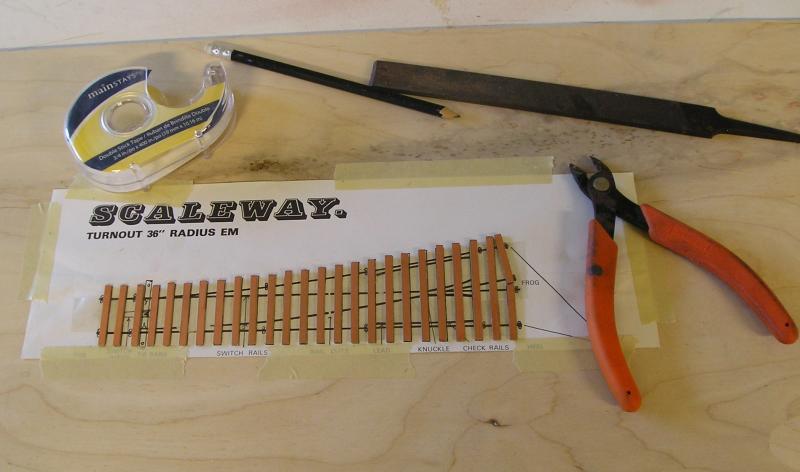
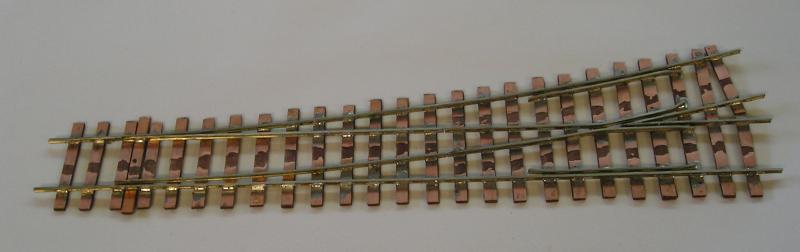
A typical point kit:
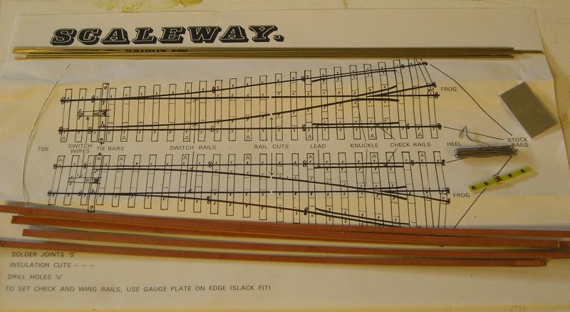
The template is for a right or left hand point, 36" rad. At the top there is some code 75 bullhead rail. At the bottom, copper clad strips. Not sure what that bit of wire on the left is for. On the right, there is a tie bar and some solder. I think that piece of metal is a flangeway guide.
I'll illustrate my build.
 Last edit: by Brossard
John
Posted
Full Member
I use double sided tape to stick the timbers down.
Next, the first stock rail.
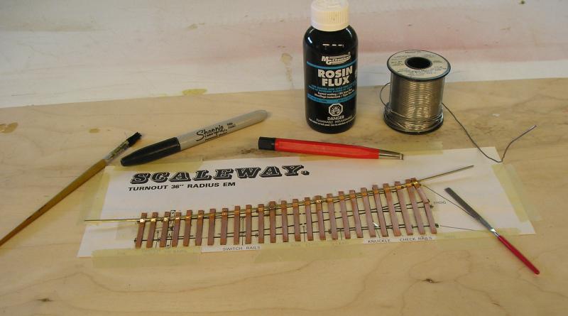
I gave it a gentle curve by pulling it between my thumb and forefinger repeatedly until it lay more or less on the template curve. The blade will have to fit very snugly to the stock rail. My method here was to file a rebate in the rail so that the flanges are down to the rail web for about half an inch and then to gently file away to blend that in until the stock rail is no longer in contact with the blade. The file with the red handle is my favourite - it has a diamond coating. It's also just about 1mm thick which comes in handy with the 1mm flangeways.
At this stage, I just tacked the rail in place in a few places. Believe me, there will be adjustments. I used the fiber pen to give the timbers a quick polish to remove any oxidation.
I like to use 60/40 solder for this job. I suppose rosin core solder is OK, but I prefer to use the rosin flux separately. It does make a sticky mess but cleans up with methyl hydrate. I set my iron to 340C for this job.
Next the vee, which is the core of the point.
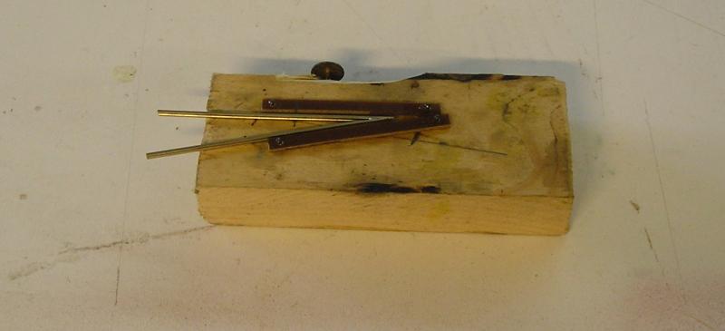
I made the 1:5 jig from a couple of pieces of copper clad and track pins. File the ends of the rail to a point until they mate up nicely and use the jig to solder them together. I used a quick dab of solder to fill a gap at the tip, then filed everything smooth. You'll want to round over the nose of the vee so that the wheel doesn't get jolted too badly when it contacts it.
Start putting things together now.
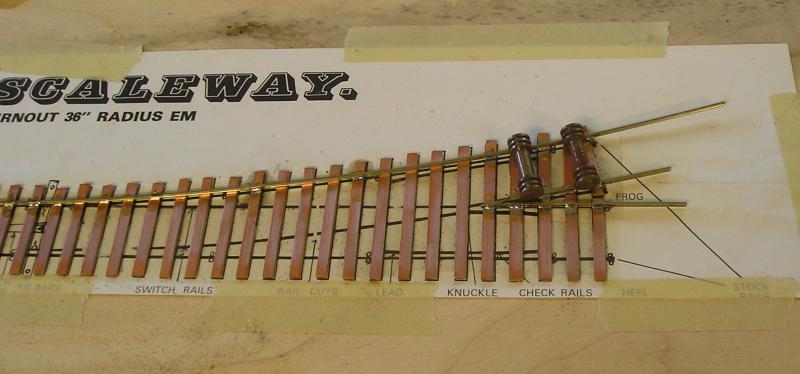
Put the vee on the point aligning it with the template. Note that the nose must sit on a timber. Use roller gauges to set the stock rail correctly.
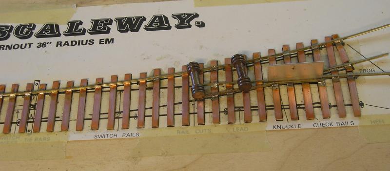
Next the wing rails. The alignment of these and the knuckles especially are critical. Spend time getting this right. The two knuckles must be dead opposite one another. The vee rails must align exactly with the wing rails so that wheels transition smoothly. The lower wing rail should be given a gentle curve before fitting. The flangeways are 1mm, you can see the gauge.
At this point, having several different length steel rules comes in handy. Make sure the straight wing rail and vee rail are in line and that the left end of the wing rail is lined up with the left end of the point. At this stage it's a good idea to try a wagon on the point to see if it runs smoothly - if it doesn't, something's wrong. Better to find out now than when the thing is done.
Next, the blades and moving towards completion.
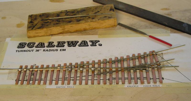
I got the straight blade in and everything is straight…now. I had to lift the wing rails and realign things to be straight :roll:
Making the blades takes a bit of practice but I made these pretty fast.
One thing that will be useful is a file with a dead edge. Most files that I have seen come with both edges with "teeth". You may need to go to a specialist tool shop to find one.
Start with the side of the rail that is in contact with the stock rail. Use the large file to remove about the half the width of the rail. Resting the rail on the piece of wood and filing away from you removes the material very quickly. Next, turn the rail over. This is where the dead edge comes in. You want to file off the top flange while leaving the bottom one. Use the large file to remove most of the material. Finally, I used the small file to finish up. You are looking for a very sharp blade end. Make sure to undercut the rail. Round over the nose of the blade. It should be a very snug fit in the rebate. Beware of any solder on the blade side of the stock rail. Remove it now.
I made the second blade which is on the wood.
That's all for now.
John
John
Posted
Full Member
'Petermac
Posted
Full Member
John
John
Posted
Full Member
I installed the straigh stock rail. Tack it at the left in a couple of places, then tack it at the right, using the hroller gauges (and you can't have too many). Use a steel rule to confirm that the rail is straight, then make a couple more tacks to hold the rail solidly. I think it's pretty important to tack the rails and not solder all the timbers. If you make a mistake, it is easier to adjust the tack joint that to have to unsolder all the solder joints.
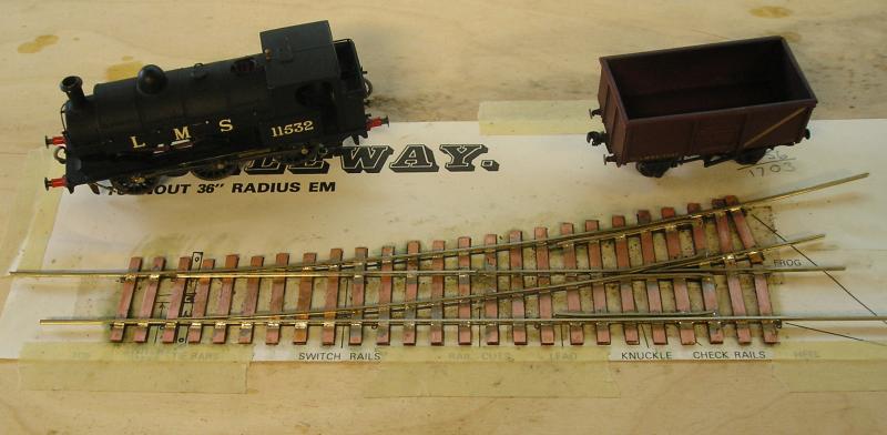
Finally, I installed the curves blade and check rails. It really helps to have an unpowered chassis to check that the point works. Install the check rails by first tacking one end roughly at the right gap then, using your 1mm gauge (supplied with this kit), tack the other end. Use the gauge to adjust your first tack and then tack in the center. Put a curve in the check rail for the diverging road, then do the same. This is slightly trickier because you have to maintain the curve. After doing this, I did find tightness and spent some time finagling things. A trick I saw Norman Soloman using is to get a hand mirror and small flashlight and position them so you can see what's going at wheel level. I found that the curved check rail was too tight and eased it's gap slightly*.
A couple things left to do are to put in the tie bar and make insulating gaps.
*I will note that the chassis pictured has Markits wheels which, while nominally to RP25 have thinner flanges than the NMRA spec (0.87mm). The flanges however, are ever so slightly thicker than the EMGS spec (0.68mm vs 0.54mm). An article in EMGS Newsletter 194 goes through an analysis and one conclusion of the author is that there could be tightness on curves due to "erosion of tolerances". Most of the wheels I plan to use are Markits are RTR, so that's something I will have to watch out for.
John
John
Posted
Full Member
Posted
Full Member
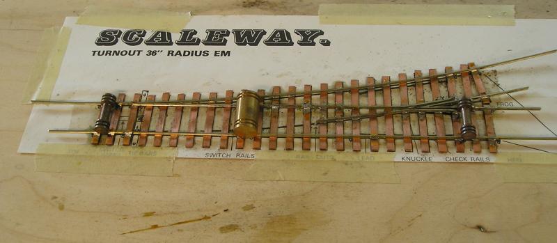
I completed the point.
I didn't like the tiebar supplied with the kit so I used a piece of copper clad. A 0.032" hole was drilled in the center. Blades were soldered to the tie bar using a scrap piece of copper clad, paxolin side to the join, as a gauge (~1mm). A couple of issues with this method:
1) The hole in the middle of the tiebar is a weak point and I have seen tiebars break at this point. The tiebar should be replaced, not easy to do when the point is laid, painted and ballasted. Note I removed the copper at one side of the hole - this reduces the stress raiser.
2) The solder joints are under stress from the point being actuated and can break. This is an easy repair - just clean and re-solder.
A better method to do the tiebar is to use brass pins as hinges. I was going to do this but could I find my pins? If you do this you can turn the copper clad over so that the paxolin side faces up. This way, after drilling for the pin holes you can a) remove the copper near the holes and b) after drilling for the actuating pin, solder a piece of scrap brass over the hole for reinforcement, re-drill the hole.
You may wonder that there are no hinges on the point blades. Slow motion point motors have sufficient power to actuate the points without these. I have made hinges using thin phosphor bronze strip soldered to the outside of the rail, but that is a fiddle.
I prefer to use my Dremel and cutting wheel to scrape away the copper from the timbers to make insulating gaps. Again something I saw Norman Soloman do (http://www.model-railway-dvd.co.uk/right_track10.php). Cutting slits as most people seem to do, makes stress raisers and is very obvious, requiring filling.
Conclusion:
1) Soldering: using rosin flux leaves you with a sticky mess. You can clean up with Methyl Hydrate but it is a bit of a nuisance. The advantage is that rosin won't corrode. You can use phosphoric acid flux and 145C solder, much less of a mess but you must wash the point carefully once built. Using paste flux and 145C solder seems the best option, the paste flux I have won't corrode (a test piece I made a week ago and left unwashed is still shiny) and is water soluble.
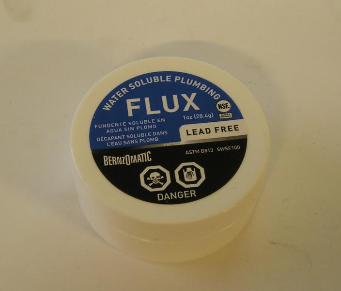
In the UK, I think there is a similar product called Templer's Telux.
2) Learning curve: something I had to climb for this build. As one gains experience and practice the relationship between track and wheels, especially at the crossing, will become better understood. Your first point may not work but keep at it.
References:
1) Iain Rice's Finescale Track - http://britishrailwaybooks.co.uk/books/ISBN/1874103003.php
2) Trax 2 - http://www.transportdiversions.com/publicationshow.asp?pubid=4070
3) Right Track 10, link above.
John
John
Posted
Full Member
A complete point can,with a bit of practise be built in about 40 minutes. However one is limited to the actual geometry of the jig one has purchased. The system you use is much more flexible but a bit more time-consumeing to build. Both have their advantages.
Meanwhile your tutorial has been very enlightening.l.lwhen I return in the spring I think I will have a go using your system.
Posted
Full Member
John
John
Posted
Inactive Member
You pretty well covered everything.
regards,
Derek.
Posted
Full Member
John
John
Posted
Full Member
1 guest and 0 members have just viewed this.