Monthly Project - February 2012
Posted
Full Member
Constructing Operational Signals.
So we have seen how a very simple memory wire "motor" can operate a signal, but the experimental rig does not provide a practical solution for most layouts as it requires some difficult fiddling and aligning under the baseboard. I looked for alternative ways of connecting the memory wire motor to the signal control wires.My first attempt was in 2007 when I constructed this pair of Ratio starter signals:-
The model is just as comes with the kit except that I have added a handrail around the decking. I was careful to ensure that the moving parts did move, but as this was my first attempt, I incorrectly ran the control wire attached to the arm itself, in front of the arms instead of behind them:-
You'll have to look closely to see that as I have not caught the focus quite right. In fact even in the flesh, it is not easy to see, and it does not affect operation, but the wire should really be behind the spectacle plate.
Being a bracket signal, wires are needed to bring the control to the central supporting pillar:-
The parts required are supplied with the kit, and with careful application of super glue in the just the right places, everything can be kept freely moving. I used short lengths of control wire for the pivots on this model. It was before I had discovered 16BA nuts and bolts.
Next come the balance levers:-
You will notice that I have pivotted the levers through the hole nearest the balance weight and not the central hole provided for the purpose. In looking at photos, I realised that in real life this is the way the balance lever is arranged, so that a pull on the signal control wire is required to set the signal to the off state. I guess this is so that if the control wire breaks between the signal and the box, the signal is safely left on.
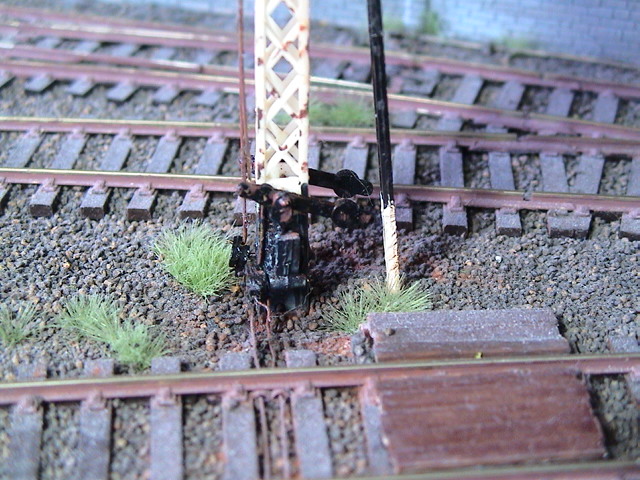
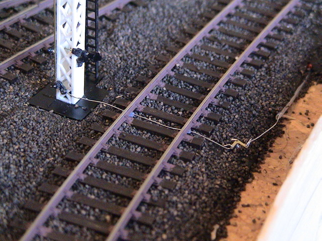
Now things moved beyond the kit. I needed to add a pair of cranks at right angles to the balance levers to feed the control wires away from the signal base. Despite the paint and weathering, you can just see them in the above photo. You can also see that I then fed those control wires under the adjacent track through small lengths of plastic tube to ensure that they did not short out across the rails.
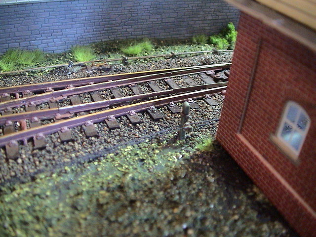
On the far side of the track (nearer the camera), I fixed another pair of cranks, but this time mounted horizontally:-

I fixed them by pinning the pivot points into pieces of sleeper, which I then glued into place on the track bed. The other side of the cranks are then connected to the ends of wire in tube - just like might be used for manual operation of points. Here is a photo I took during construction which shows one wire in place:-
At the other end of the wire in tube, I fitted the memory wire motors:-

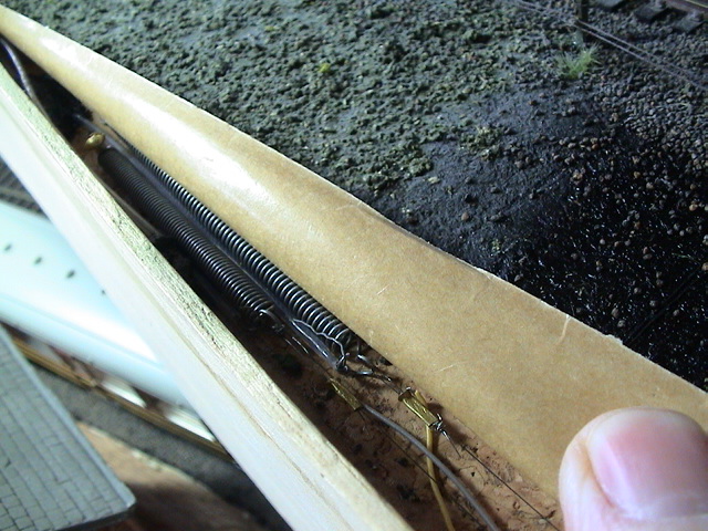
I have just taken the above two photos, so you can see how easy it is to access the motors if needed - although I have not had to in the 5 years since I constructed this. When the scenery is back in place it looks like this:-
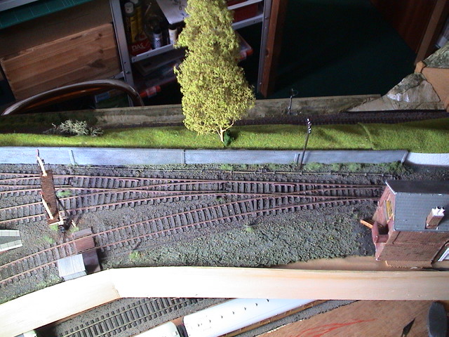
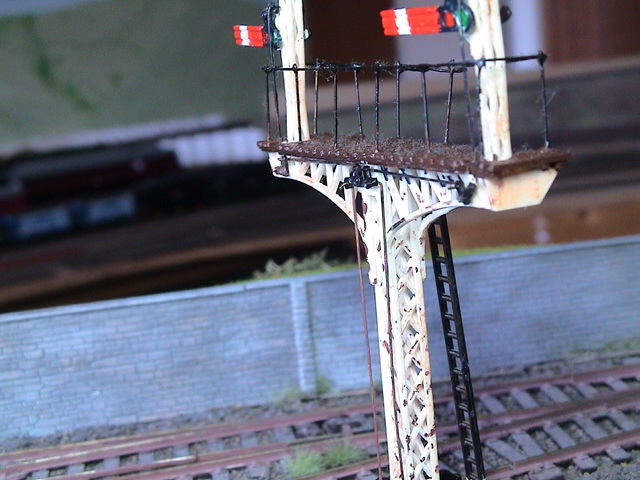
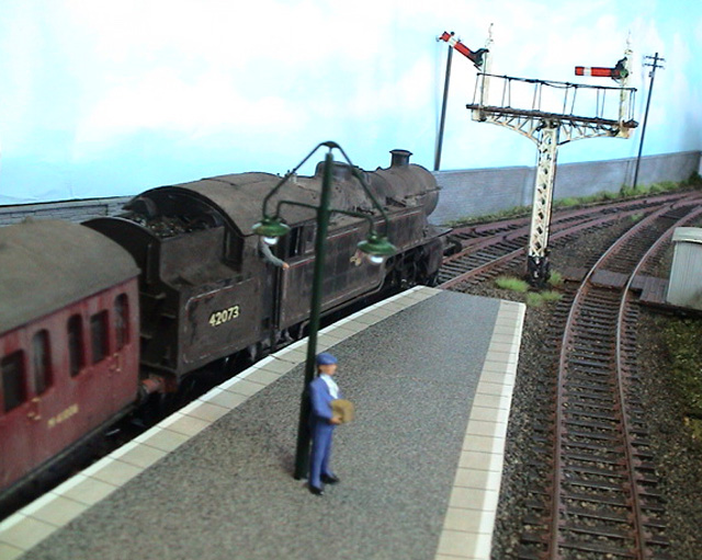
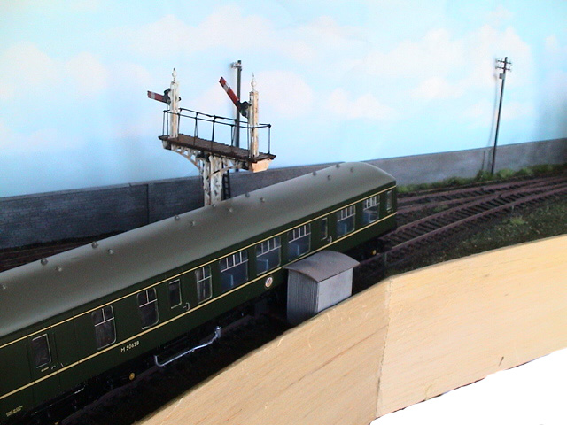
Note the lineside shed over the cranks at the side of the track:-
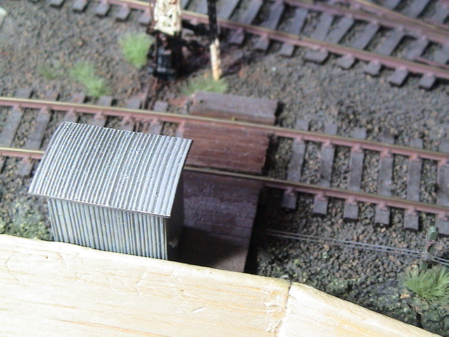
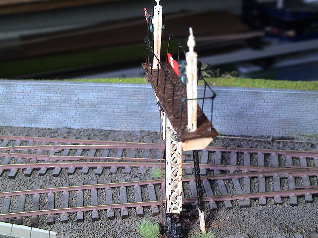
The "threads" leading out from under the walkway are meant to be representations of the real signal control wires, and here is how they end up at the signal box:-

As I mentioned earlier, these have been working for a number of years now with no problems. They are connected to 12volts via a single 22 ohm resistor and a slide switch and a changeover microswitch on the point motor seen above which sets the route for either platform. Thus with the switch on, the correct signal goes off, depending on the point position.
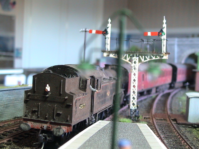
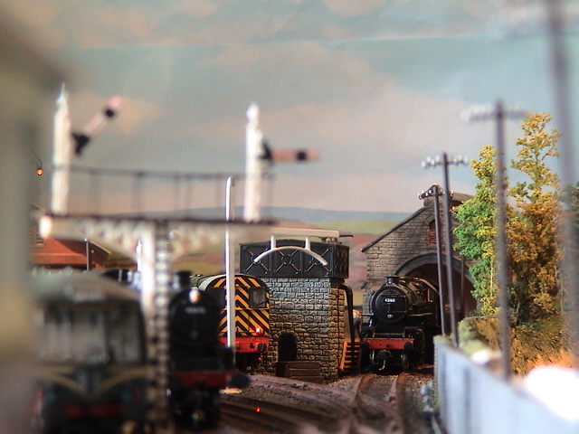
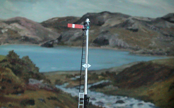
And just for self indulgence, a distant shot I like, with the signals purposely out of focus in the foreground:-
 Last edit: by Geoff R

Posted

Full Member
Does the wrie in tube "rodding" have to be taught ? In the 5th and 6th shots, there seems to be a fair bit of play or was this just "under construction" ?
Given that the memory wire motor only offers around 3mm of movement, any "slack" would tend to stop the arm moving ……..:roll::roll:
'Petermac
Posted

Full Member
Where did you get the little brass angle cranks that you use And how do you arrange the micro switches for the signals in connection with the slide switches you use to change the points ?
"The only stupid question is the one you don't ask"
Regards.
Tony.
Regards.
Tony.
Posted
Full Member
The outer sleeve of the wire in tube does need to be firmly clamped down, and that is achieved by the scenic layer on top of it. The exposed wires are quite stiff, so do not flex and create slack. The signal arm and attached cranks are very light so there is very little resistance to the control wires movement.Lovely stuff Geoff. :thumbs
Does the wrie in tube "rodding" have to be taught ? In the 5th and 6th shots, there seems to be a fair bit of play or was this just "under construction" ?
Given that the memory wire motor only offers around 3mm of movement, any "slack" would tend to stop the arm moving ……..:roll::roll:
Posted
Full Member
Looking great Geoff.
Where did you get the little brass angle cranks that you use And how do you arrange the micro switches for the signals in connection with the slide switches you use to change the points ?
The little brass angle cranks come on a fret from Model Signal Engineering and I will be covering them in more detail when I get on to brass signal construction.
The microswitch arrangement can be kept very simple as follows:-

Posted
Full Member
How long can you keep the signal memory wire energized before you need to switch off the power ?.
"The only stupid question is the one you don't ask"
Regards.
Tony.
Regards.
Tony.
Posted
Full Member
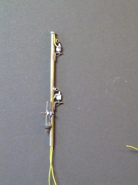
So here is a build of the latest way I have found to fit the memory wire motor. I am using the single arm Ratio kit built up earlier, but I have removed the balance lever:-

… note that it is simple a matter of undoing the 16BA bolt, and now the end support plate stays perfectly in place, glued to the post. I am fitting another balance lever, but this time have drilled out the hole nearest the balance weight as the pivot point, so that there will be two operating holes on the other side of the pivot. One for the arm and one for control.
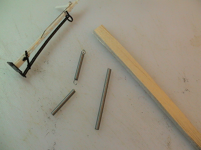
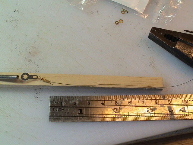
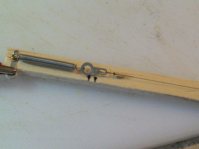
Now to the motor. I have cut a 15cm length of balsa about 1cm square, and I have selected a light spring from the memory wire starter kit (actually I lie, because I have bought a second packet of springs from C&L). I have then cut the spring in half and pulled out each end. One as a loop and the other as a hook. I think the photo above shows that clearly.
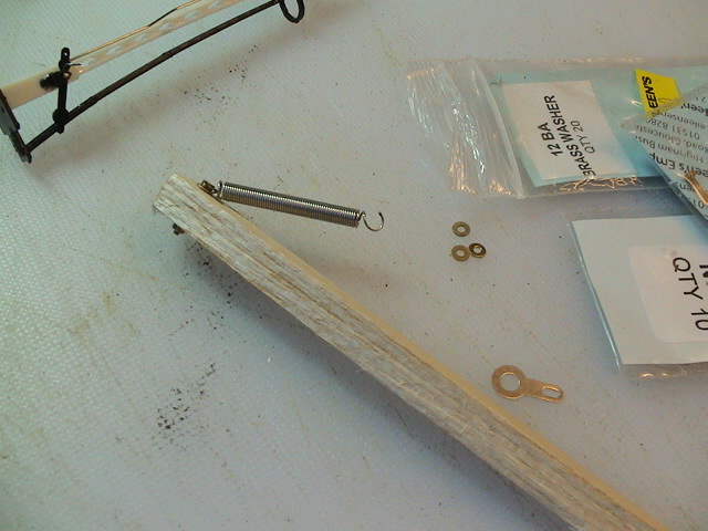
Fix the spring to one end of the balsa stip by passing a 12BA bolt (or similar) through the looped end of the spring and then through the balsa. I use a washer as well, and as you will see in a later photo, I also added a solder tag under the bolt head which is not shown below because I forgot it initially:oops::-
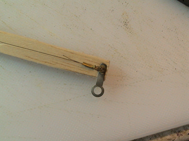
Now I take one of the solder tags supplied in the kit and drill a 0.6mm additional hole as shown:-
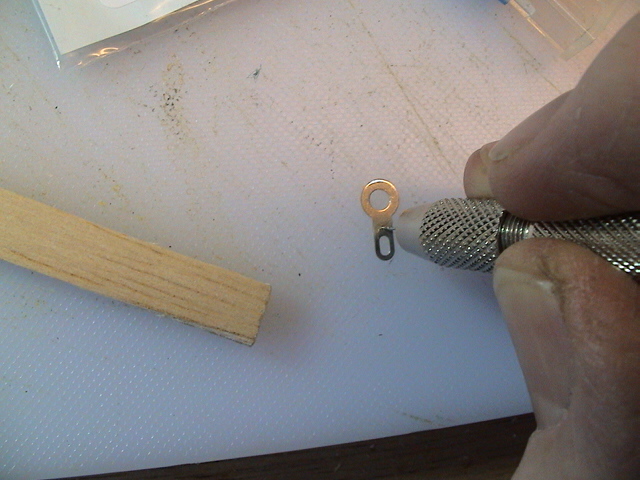
… this hole will take the control wire.
I have also drilled a new 0.6mm hole in the base of the signal, under the outer balance lever operating hole. The signal arm has its control wire fitted to the inner hole:-

I now fit a new control wire to the balance lever sliding it through this new hole in the base. I have kept it fairly long for now:-

Thanks to a very responsive service from C&L, I have now replenished my stock of memory wire. Take one end and thread it carefully through one of the supplied crimps:-
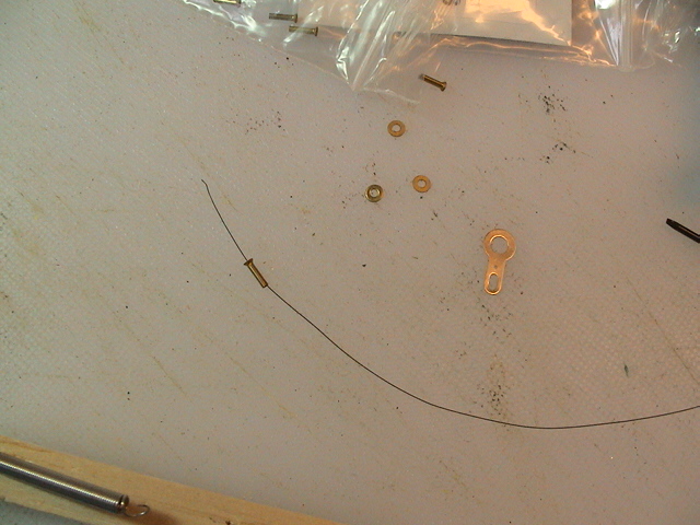
Then thread the wire through the long hole of the drilled solder tag:-
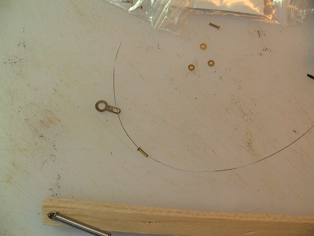
and then back down through the crimp:-
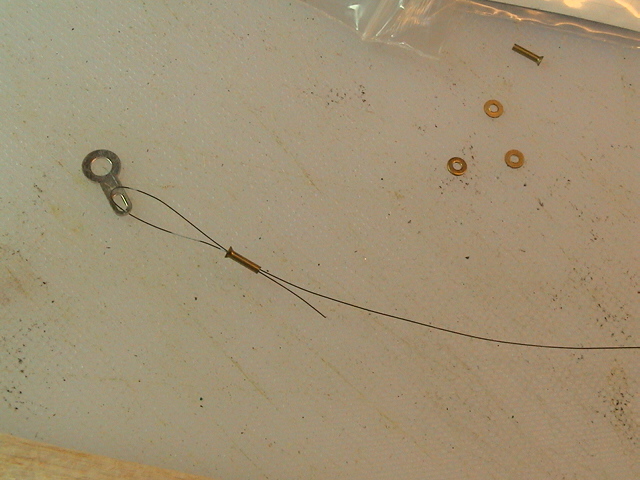
Carefully pull the assembly together. It doesn't have to be tight, but you don't want to waste memory wire:-
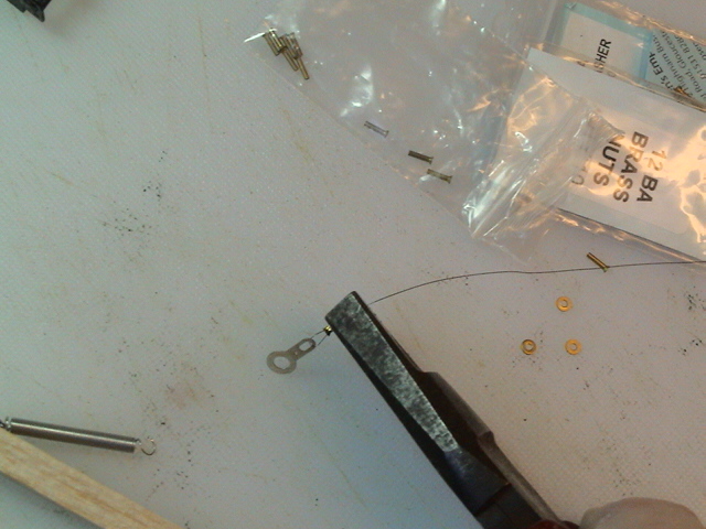
Now squeeze the crimp. I just use pliers, but it does require plenty of pressure to make sure that the memory wire does not slip through:-
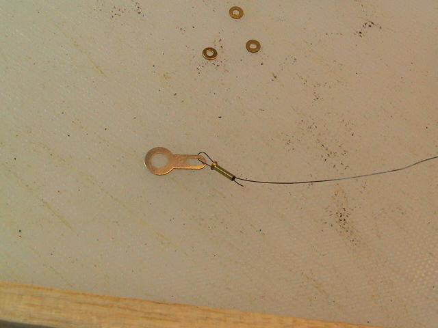
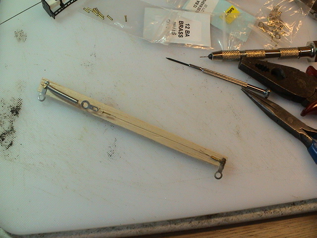
Loop the solder tag over the hooked end of the prepared spring and measure the memory wire out along the length of the balsa strip. I use about 10cm of wire, which means that I will have enough for 10 signals from one reel of wire:-
(Have to leave it there as I am on the school run)
to be continued……
Posted
Full Member
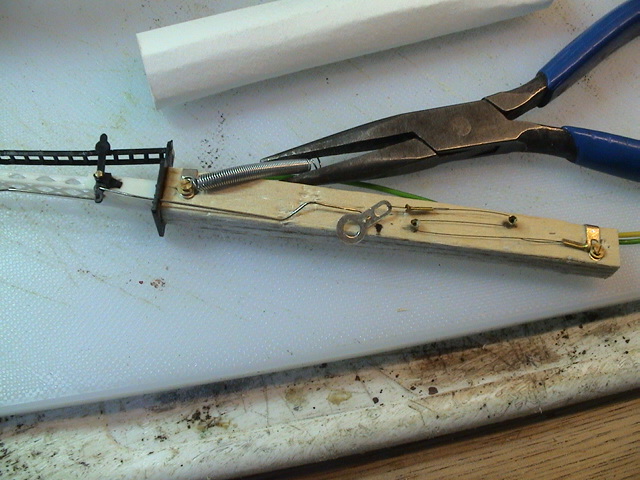
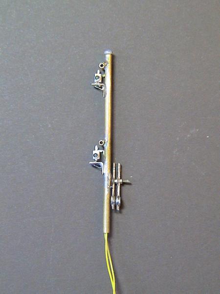
So this is what our memory wire motor looks like (you can now see the tag I added at the spring end as well - however, I also mention later when attaching to the signal, that it would have been better to have the tag pointing the other way - 180deg - see this 4 photos later):-
Time to test the motor. I am connecting to the 3v battery clip again. The left hand black mark shows where the 0.6mm hole in the moving solder tag sits when the motor is at rest:-
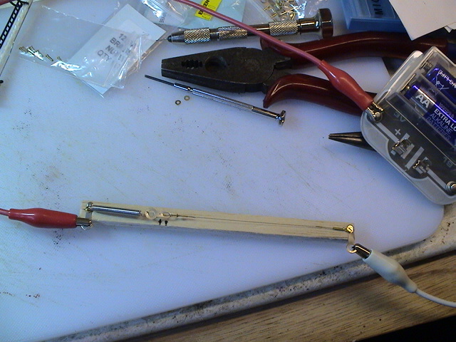
and here is a close up when energised:-
Next we fix our motor to the base of our signal. I have used super glue, which is super fast and super fast! So BEFORE glueing, make sure that the motor is in the right place - take a careful look at the next photo:-

you can see that I have positioned the memory wire motor so that the new long control rod sits alongside the spring. You may also have noticed that I have moved the top solder tag onto the other side so that it stays out of the way of the control rod. I have also bent it around the balsa so as to minimise the size of hole required in the baseboard under the signal:-
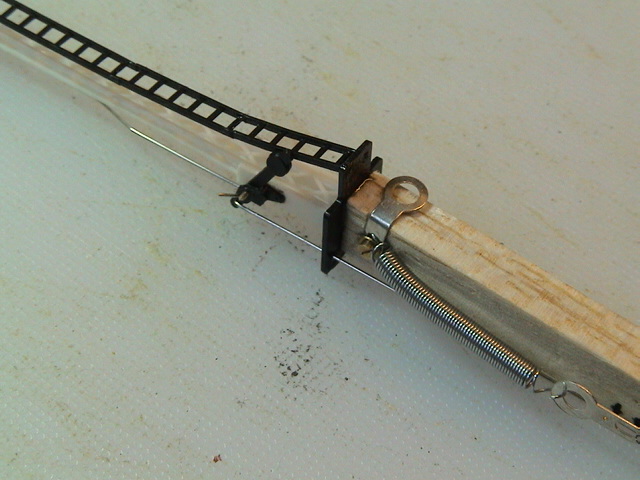
Now we need to fix the control wire from the balance lever to the moving solder tag by bending it through right angles and pushing it through the 0.6mm hole we drilled:-

Remember to have the arm in the on state when doing this as the motor is at rest. Provided that the length of the control wire is nearly correct, trim it off.
Fine adjustments to the position of the signal arm can be made by setting a small pair of cranks in the control wire - which you can just see under the spring:-

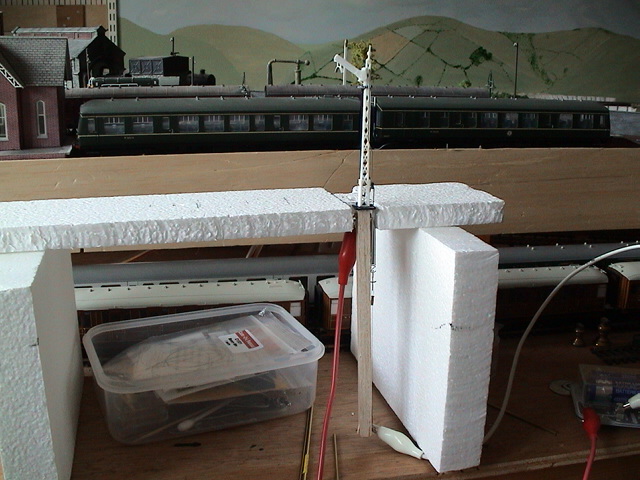
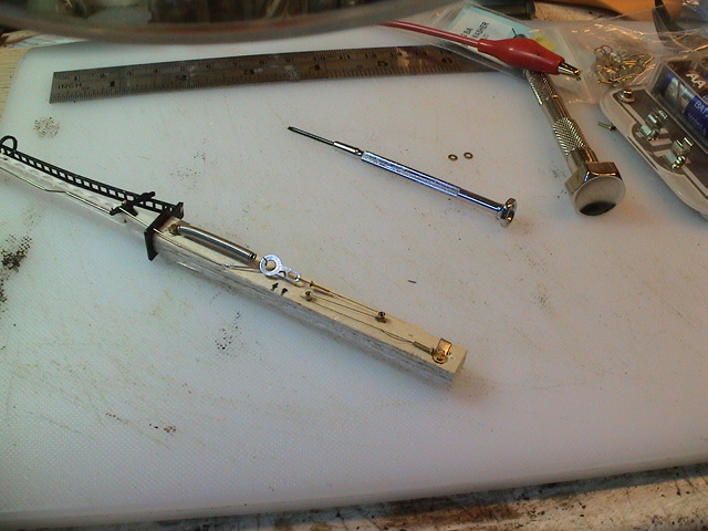
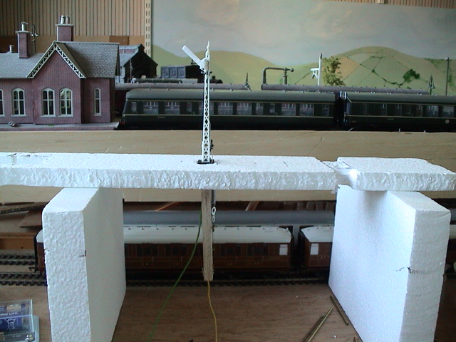
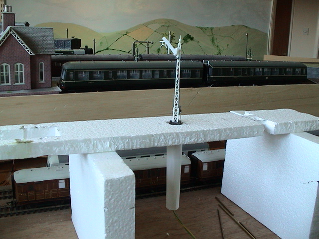
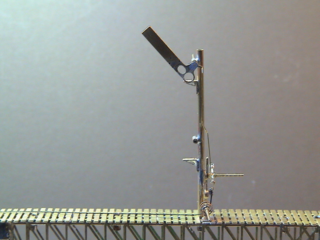
Here we have our finished operational signal sitting in a test rig representing the layout baseboard. You can see that a connection needs to be made to each of the fixed solder tags and then the two wires routed to the power source and any switching used. A hole around 15mm in diameter should be plenty to insert the motor through, and the depth taken below the baseboard is about 120mm depending on the baseboard thickness:-

And here is our signal with the motor energised:-
Just a word of caution when making the electrical connection to the solder tag at the bottom of the motor. The memory wire can quickly lose its properties if heated for too long by a soldering iron, so although I have successfully soldered some of my motors close to the wire, I would suggest that it might be better to remove the tag from the bolt, solder on the electrical connection, and then refit the tag. There is no problem with the top fixed tag as this is at the opposite end of the spring to the memory wire.
Next I will briefly show some of the control circuit I use and demonstrate how this could be connected to a DCC Accessory decoder and even controlled by RR&Co - maybe that will persuade John Dew to have a go!!!
Posted
Full Member
The top solder tag can be shared as a common return, and two separate bolts fitted at the bottom end for tags to control each of the signal arms. Just a little care needs to be taken to ensure that the bottom bolts do not come in contact with each other.
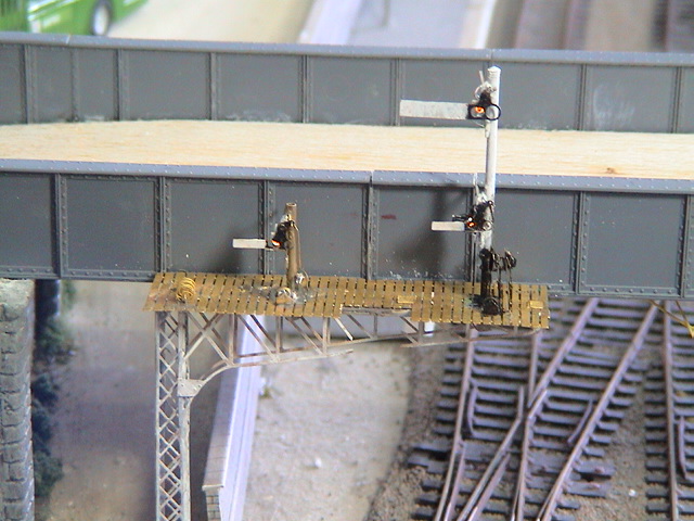
I have arranged 6 motors (3 each side) on a single slightly wider strip of balsa for my gantry signal operation. Here is a view of one side during construction:-
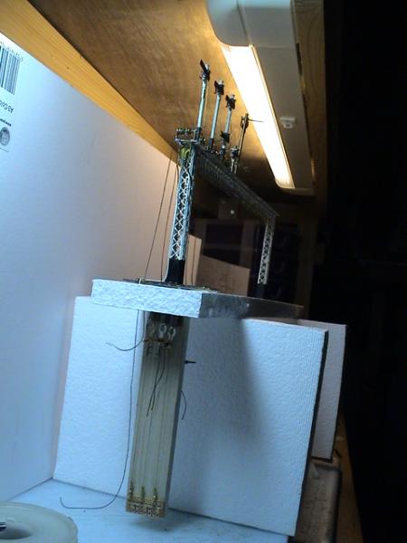
More of this later.
Posted
Full Member

The two relays are nothing special. I use these as they are very cheap:-

http://www.rapidonline.com/Electronic-Components/12v-Dpco-Subminiature-Signal-Relay-EM2-60-1982
The operation of the circuit is as follows. With both relays in their un-energised state, the memory wire is at rest. If the left hand "Signal OFF" contact is briefly connected to 0v either by an accessory decoder output pulse, or a push button or an infrared sensor (which I use and will explain when I talk about my gantry), then relay 1 latches on, providing power to the memory wire via the on board resistor.
The signal is then returned to the ON state by a similar brief pulse at the right hand contact.
If accessory decoder outputs are used, then a pair can be connected in the same way as connecting to each end of a peco type point motor. Instead of the output setting the point left or right, the output will set the signal OFF or ON. Of course this can then be controlled by RR&Co - John ???
The two relays and the resistor are all of similar size, so a small copper track board will take them side by side very neatly.
Posted
Full Member
Thats extremely interesting I have to say.Thank you for such a splendid tutorial.
A few questions if I may.
(1)I gather the wire used in the linkages is 0.5 / 0.6mm ? Is this nickel silver wire ?
(2) Fine adjustments to the position of the signal arm can be made by setting a small pair of cranks in the control wire - which you can just see under the spring:-
What cranks are you referring to as I couldn't see anything under the spring ?
(3) Is there a danger that the mechanism sticking down like that under the baseboard will get damaged by someone or something under the layout ?
Resistors & Ba screws & nuts have been ordered.Looking forward to trying this out.
"The only stupid question is the one you don't ask"
Regards.
Tony.
Regards.
Tony.
Posted

Full Member
am I right in thinking the memory wire contracts when energied and the spring is thre just to ensure it re-straightens in the correct plane - or is the spring necessary to re-lengthen the wire once the power is off ?
Also, you're using 75mm of wire with a low amperage - would a shorter length work with a higher current ?
The theory behind these two related questions is would it be possible to use a short length of memory wire horizontally under a bracket signal, using an actual weight on the operating arm to reset the signal to danger ?
Thanks
Stu
Stubby47's Bespoke Model Buildings
All photos I post are ©Stu Hilton, but are free for use by anyone.
Posted
Full Member
The wire I have used in this post is that supplied within the Ratio kit. It may well be nickel silver and it appears to be around 0.5mm in diameter. On my brass signals I use 0.45mm brass wire. It is easier to bend.(1)I gather the wire used in the linkages is 0.5 / 0.6mm ? Is this nickel silver wire ?
(2) Fine adjustments to the position of the signal arm can be made by setting a small pair of cranks in the control wire - which you can just see under the spring:-
What cranks are you referring to as I couldn't see anything under the spring ?
Sorry, cranks was probably the wrong word. Here is a photo with the spring held out of the way:-
I was referring to the "crank" in the control wire. The offset is useful for alignment, but the angle wil affect the overall length. The more it is towards a right angle, the shorter the overall length. Thus the length can be adjusted in relatively small increments to get the position of the arm just right when the motor is at rest and when energised.
You may have also spotted something different in the above photo. I have wrapped the memory wire back onto itself in a squashed "S" shape. This shortens the "motor" by more than an inch. It still works the same, but the increased friction reduces the amount of movement a little, and could really do with a stronger spring for the return. More below.
I guess this depends on what sort of layout construction you have. Mine is all fixed in a dedicated train room so I have lots of flexibility about what I do under the boards. The basic thought behind this vertical solution, though, was to try to contain the motor in about the same depth as a Tortoise point motor, which is roughly 4 ins.(3) Is there a danger that the mechanism sticking down like that under the baseboard will get damaged by someone or something under the layout ?
If you "wrap" the memory wire as in the above photo, the depth required reduces to just a little over 3 ins. To accommodate a slightly shorter movement, I have changed the use of the operating holes on the balance lever:-
The arm is now connected to the further hole, and the motor to the hole nearer the pivot. This gives a little magnification of the movement due to the action of the lever.
Here it is in action, now with the electrical connections soldered into place:-
and finally with a smart card tube to cover all the works:-
By the way, I got a new aid this morning:-
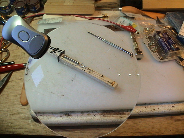
An excellent rimless magnifier with integral white light. I think it will be very useful, especially for fixing 16BA nuts onto 16BA bolts!
Posted
Full Member
Yes, Stu, you are correct about the memory wire contracting, but it does have to be held taught or there is no usable movement. The spring holds the wire taught both when energised and again when the power is off. It does not really re-lengthen the wire, rather it keeps it in a straight line.am I right in thinking the memory wire contracts when energied and the spring is thre just to ensure it re-straightens in the correct plane - or is the spring necessary to re-lengthen the wire once the power is off ?
Also, you're using 75mm of wire with a low amperage - would a shorter length work with a higher current ?
In theory, yes. However, I am not sure what the maximum current carrying capacity is of the wire. It is hard to find out much about it. It is very tiny - about the thickness of human hair!, so it may "fuse" if it carries too much current.
The theory behind these two related questions is would it be possible to use a short length of memory wire horizontally under a bracket signal, using an actual weight on the operating arm to reset the signal to danger ?
Provided you use a spring to keep the wire taught, this will work - taking into account my comment above about higher current. On my gantry, the memory wires only pull the signal arms to the OFF position. The memory wires are connected to the arms via cotton thread passing over pulleys so there is no direct return "push" to the ON position. I rely on the weight of the arms together with the weights on the balance levers, just like the real thing!!!
Posted
Full Member
It is the first brass one I made and is from a MSE kit. It has a working oil lamp behind the spectacle plate, and connects to a horizontal memory wire motor above the baseboard through a crank fitted to the base of the post.
Posted
Full Member
With all this "tiny" stuff and talk about "electronic bits", I was starting to wonder if it would be better for me to buy "RTR" signals ……………….I'll go and open a bottle whilst I consider the problem ……:cheers
'Petermac
Posted
Full Member
Stubby47's Bespoke Model Buildings
All photos I post are ©Stu Hilton, but are free for use by anyone.
Posted
Full Member
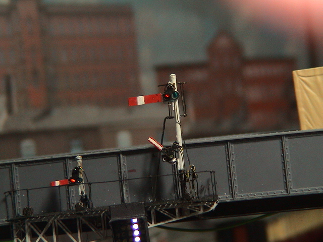
Here are a few on a bracket with working lamps:-
And this is what they look like with spectacle "glass" in place (coloured plastic sheet):-
Posted
Full Member
Stubby47's Bespoke Model Buildings
All photos I post are ©Stu Hilton, but are free for use by anyone.
Posted
Full Member
They contain a yellow led and are shaped to represent an LNER style oil lamp. This photo from the top of this page shows one fitted to the rear of a tank:-

and here is a shot of the one on the front:-
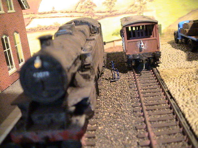
Sorry, the front of the loco is out of focus as this was actually a photo of the ground frame. You can also see a red lamp fitted to the rear of the guards van.
Last edit: by Geoff R
1 guest and 0 members have just viewed this.