A Home brew hand held controller
Posted
#126246
(In Topic #6609)
Guest user
How I built my own DC handheld controller
PreambleSince I rewired my layout I have provided for two controllers to be used.
Once the extension is built the fiddle yard will be up to 8ft away from the main operating position. To make operations easier I have introduced "cab control" where a train leaving the fiddle yard is under the control of the "main" operators controller.
A train travelling to the fiddle yard will be under the control of the fiddle yard operators hand held controller.
switching from one controller to the other is done manually by a switch on the main panel.
This of course requires two controllers. As I only have one (a Gaugemaster hand held) I decided to build another.
This brings me on to the main topic of this thread.
Circuit diagram
The circuit of my home brew controller is shown below.

It's a very simple design using only a few components but, the control of locos from this controller is stunning.
Because it is a closed loop controller using the back EMF of the motor as feedback the slow start and smooth running beats a lot of ready to use designs.
Note that there is NO smoothing capacitor, this is because the voltage needs to fall though the 0v point for the back EMF voltage to be measured. If a smoothing capacitor was fitted the controller would still work but, slow starts and smooth slow running would be impossible.
I take no credit for this circuit as it is quite a common type of control for small DC motors.
Construction
The controller (less transformer of course) is built into a small plastic box.
The method of construction though needs some explanation.
Instead of using a printed circuit or strip board I have used my "Ugly bug" technique using "islands" of PCB material with the components surface mounted on them.
the picture below shows what I mean.

I did however use a small piece of strip board for the rectifier diodes (seen on right hand side of box).
I find this method of construction very simple to do when just a few components are involved and this method lends itself to prototype development, allowing quick component changes when developing new ideas.
Here's a close up of the main assembly

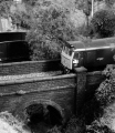
And finally a picture of the finished and tested controller along side my Gaugemaster unit.

If anyone is interested in building one and needs more info ,I'll be happy to help.
Cheers for now
Frank
Posted

Full Member
I reckon you should start taking orders for those mate!
:cool wink
Cheers,John.B.:thumbs

Posted
Full Member
…now if you could just do something as simple for my DCC setup …………
Posted
Guest user
Frank,
       I reckon you should start taking orders for those mate!
:cool wink
Cheers,John.B.:thumbs
Posted

Inactive Member
Max
Port Elderley
Port Elderley
Posted
Guest user
That size box is ideal for those who like to move arond the station in shunting, etc.
A good job done then Frank.
Posted

Full Member

Posted
Inactive Member
Can I suggest a couple of changes or additions as it were.
The 10 K resistor to the base of the BC107 transistor, I suggest you replace with a 1N4148 diode and 10K resistor in series. The reason being that the maximum base-emitter reverse voltage of the BC107 is probably around 5 or 6 Volts ( No, I've not dug the datasheet out so can't quote an exact figure) but ANY reverse voltage b-e is not good design and liable to give unexpected results. The reverse voltage will be generated by the back EMF of the motor, when the input voltage is zero or close to it, from the alternating voltage input.
Also , add a 1 or 2.2UF 25V capacitor from the slider of the speed pot to the negative supply ( "chassis" as I usually call it) as pots after a little exposure to air, get 'noisy' ( electrically ) which means that what could be high frequecy spikes , causing the power transistors to turn off and on at high speed into an inductive rotating load- the motor. Again , its circuit protection and premature component failure is the reason.
Finally you have the collector of the BC107 transistor connected to the base of the Darlington TIP47 output transistor, so any leakage current c-e of the BC107 caused perhaps by high temperatures has nowhere else to go but into the b-e junction of TIP47 and get amplified by the high Hfe of it… Possibly leading to thermal runaway with such a small heatsink. I would add a 10K , 0.5W resistor across the b-e of the TIP47 output darlington.
And lastly , I would add across the rectified supply, (across the speed pot is easier to visualise in the circuit as drawn) a 'snubber' of 10 ohms 0.5W and 0.1UF in series so any mains bourne transient pulses , are reduced to the components in the controller. Don't forget a fuse or thermal trip somewhere in the supply leads , be it in the controller or near the transformer, just in case the unexpected happens…
Hope that helps to give a little bit more long term reliability and stability.
 Last edit: by diablo
Posted
Full Member
 thumbs Can you come over and help me out rebuilding some radios and transceivers?:cheers
Posted
Guest user
Hi Dukedog,
Can I suggest a couple of changes or additions as it were.
The 10 K resistor to the base of the BC107 transistor, I suggest you replace with a 1N4148 diode and 10K resistor in series. The reason being that the maximum base-emitter reverse voltage of the BC107 is probably around 5 or 6 Volts ( No, I've not dug the datasheet out so can't quote an exact figure) but ANY reverse voltage b-e is not good design and liable to give unexpected results. The reverse voltage will be generated by the back EMF of the motor, when the input voltage is zero or close to it, from the alternating voltage input.
Also , add a 1 or 2.2UF 25V capacitor from the slider of the speed pot to the negative supply ( "chassis" as I usually call it) as pots after a little exposure to air, get 'noisy' ( electrically ) which means that what could be high frequecy spikes , causing the power transistors to turn off and on at high speed into an inductive rotating load- the motor. Again , its circuit protection and premature component failure is the reason.
Finally you have the collector of the BC107 transistor connected to the base of the Darlington TIP47 output transistor, so any leakage current c-e of the BC107 caused perhaps by high temperatures has nowhere else to go but into the b-e junction of TIP47 and get amplified by the high Hfe of it… Possibly leading to thermal runaway with such a small heatsink. I would add a 10K , 0.5W resistor across the b-e of the TIP47 output darlington.
And lastly , I would add across the rectified supply, (across the speed pot is easier to visualise in the circuit as drawn)Â a 'snubber' of 10 ohms 0.5W and 0.1UF in series so any mains bourne transient pulses , are reduced to the components in the controller. Don't forget a fuse or thermal trip somewhere in the supply leads , be it in the controller or near the transformer, just in case the unexpected happens…
Hope that helps to give a little bit more long term reliability and stability.
Thanks for your comments Diablo.
I take on board all your suggestions and reply with the following comments.
The diode across the controller output serves to protect the semiconductors from back EMF from the inductive load and IMHO is capable of doing the job.
The 10K resistor is only there to protect the BC108 from excessive base current should the output of the controller be short circuited at full chat.
The resistor across the b/e of the darlington pair you mention is not required in this case. The TIP147 device has it built in to the "chip"along with thermal protection.
The capacitor idea is OK but, by smoothing the control voltage you will tend to lose the desired control characteristics of the controller as the base/emitter of the BC108 acts as a voltage comparator and the sensitivity will be reduced.
I will add that I have built and used this circuit several times (albeit as panel mount controllers)and have never had a failure yet. The TIP147 is built like a brick s**T house and will take a fair bit of abuse before failure.
The only concern I have with the design is the size of the heat sink. It could do with being a bit bigger, i am working on that. Maybe using a Diecast aluminium box would help here,
As for overload/short circuit protection. Yes, some sort of device is needed ideally a solid state device (I'm working on that) or a thermal trip.
Once again thanks for your input it is appreciated,
Cheers
Frank
Posted
Guest user
Frank,
       I reckon you should start taking orders for those mate!
:cool wink
Cheers,John.B.:thumbs
funny you should say that John!
I am seriously considering making and selling these devices along with other electronics bits and bobs such as CDU's, Power supplies and so on.
I could even offer a custom built control panel building service.
watch out on the forum for more details.
Posted

Full Member
Go for it FrankFrank,
I reckon you should start taking orders for those mate!
:cool wink
Cheers,John.B.:thumbs
funny you should say that John!
I am seriously considering making and selling these devices along with other electronics bits and bobs such as CDU's, Power supplies and so on.
I could even offer a custom built control panel building service.
watch out on the forum for more details.
thumbs:thumbs There's an order waiting for you here in France immediately !!!!Now, back to your description. Where does the red wire go …………………….:shock::shock::shock::shock:
 I only know about red, blue or black and green/yellow. :oops::oops:
'Petermac
Posted
Guest user
thanks for the comment and support.
Yes, I have been thinking about something like this since I became unemployed.
I have talked it over with SWMBO and she has given me her support in this venture.
I hope to start off in a small way just like Dave Bentley did when he started west coast miniatures.
I am looking for a name to use for this venture so am open to ideas from anyone looking at this thread.
I shall be creating a web page over the next few days/weeks and will post a link when I have done that.
I don't propose to make a great deal nof money from this venture, so long as I cover my costs and reinvest a few bob back in to it I'll be happy.
Thanks a lot Peter
talk soon
Cheers for now
Frank
Posted
Guest user
Pen-Y-Bont Model Rail Electronics
Posted
Full Member
"Dukedog Controllers/Electronics"
"Cambrian Model Electrics"
Although there is already a company making model rolling stock under the "Cambrian" banner …………………:hmm
'Petermac
Posted
Full Member
Well, perhaps not.
Good luck with it anyway!
Last edit: by Bod
Posted
Guest user
while i have been off line and you have been scratching your heads:hmm
I have come up with this http://www.frankcollin…blueyonder.co.uk/MRET.htm
Not much to look at yet but it's a start!
More info when I add to the pages.
cheers!
Frank.
P.S. I hope bob doesn't mind me plugging this venture on his forum.
If it's a problem Bob, let me know
Frank
Posted
Guest user
I think you mean DCC Enthusiasts
Posted

Full Member
One question - would this controller work with all RTR type motors - or only those that produce back EMF (or do they all - I don't really know…) ?
Stu
Stubby47's Bespoke Model Buildings
All photos I post are ©Stu Hilton, but are free for use by anyone.
Posted
Guest user
Hi Stu,Frank - great idea - and I'd definitely be a customer !
One question - would this controller work with all RTR type motors - or only those that produce back EMF (or do they all - I don't really know…) ?
Stu
Yes, the controller will work with any 12V DC motor including those fitted to RTR models and portescape types too.
I still have to work out a reasonable selling price for the hand held but, it will be a lot lot cheaper than the Gaugemaster unit!
Cheers!
Frank
1 guest and 0 members have just viewed this.