RR&Co and Voltage
Posted
#121885
(In Topic #6362)

Full Member
Brian wrote
The elephant in the room in all of this is the layout wiring. Is anyone, other than me, using a setup with equal voltages in detected and undetected sections?
With the unbalanced system there could be difficulties in setting up contact distances and positioning of stop markers when the time comes to use the same markers for engines and trains of varying lengths. What are the effects of a delayed switch off to stop flickering? It ought not to be a problem for me so I haven't thought this through - has anyone else? May be this voltage thing needs a whole new thread.
This is a quote from Brian's post in the Box Car thread .
I am a self taught hobby electrician:shock: with no formal training and I tend to do wiring by numbers so please forgive my clumsy descriptions/questions…………I will definitely benefit from a thread of this nature
First off I dont understand "equal voltages in detected and undetected sections"…………could I have a dummies guide please?

Posted
Guest user
Posted
Full Member
it depends on the input circuit for the detector. I have a single 8 way LDT occupancy detector, and like the frog detector I built myself, it uses diodes to create a detectable voltage when current flows through them to the track - and therefore follows Brian's logic above.
However, I have seen descriptions of detectors for DCC current which simply use a coil surrounding the wire carrying power to the track. Because the DCC signal is an AC one, it will induce a current in any coil around it. This is a smart way of providing both an isolated detection AND one that does not cause any voltage drop. As Max, who is using Lenz detectors, did not see a replication of Pete's detection of a loco entering an already occupied block (Pete uses LDT like me), it may be that the Lenz detectors use this coil method.
So, before adding diodes to non detected sections, we need to be sure about what is happening inside the detectors we are using. I guess that the simple test I suggested to Max and Pete about pushing a loco slowly across a gap between an occupied detected block and a permanently connected section of track would prove the point one way or the other.
If RR&Co continues to show occupancy while the second loco is being pushed across the gap, then the detectors in use are NOT dropping any voltage. If however, the section shows unoccupied while the loco is across the gap, the detectors are dropping voltage. In the latter case, if we do not want this phenomenon to occur - which could easily fool RR&Co - then we should disconnect the permanently connected track from the DCC bus and then add two power diodes in series with the same rail as that coming through the detector in the adjacent block and try the test again to see if occupancy now stays constant.
If adding the two diodes does not make a difference, it may require one or two more, but if that still doesn't work, we would need to learn more about how the detector is configured.
SIMPLES??
Posted
Full Member
Simples may be something of an oversimplification for me but I sort of follow the principle.
Like Max, I use Lenz occupancy detectors and I have just come up from the railway room where I checked the voltage with my multimeter (?) and it was identical on a block where the power is fed in via a Lenz LB 101 and a point where it is powered direct from the DCC bus
After lunch I will try the test with a loco
Posted

Inactive Member
Max
Port Elderley
Port Elderley
Posted
Full Member
What I loosely called a Multimeter is a $35 thingy that I use to check I have current (oops voltage) and polarity when installing points………..and this week end I learned (for the first time!!!) how to use the resistance bit to check there is no continuity when I finally start chipping my split chassis locos…………I warned you I was an amateur
I will take a photo so you guys can let me know if I have the wrong equipment
Posted
Inactive Member
Max
Port Elderley
Port Elderley
Posted
Guest user
Posted
Guest user
The same practice can be used to find a dirty electrical track joiner.
Posted
Full Member
The moment the front wheels of the loco bridged the rail gap and made contact the new block turned pink and the old block remained pink until the last contact wheel cleared the gap when the old (now empty) block then turned white. The colour change was immediate ……no flickering
This is with the Lenz system of LB 101s connected to a LR 101 which I have found them to be robust, stable and accurate.
Not sure what it proves though:roll:
Posted

Full Member
What we are trying to see is as the loco crosses the gap from a point (dcc powered undetected section) into a occupied detected block, does the block turn white until the whole of the second loco is in the block and it returns to pink. So ithe occupied block should go pink - white- pink as the loco entrers. If this is not the case we can assume lenz use current coils for detection as opposed to diodes like the S88's.
Pink-white-pink is the effect we see with the S88;s and we are able to use this, in effect as a CI. This is why i confused everyone by saying i don't use a VC for joining, i was using flashing white as the trigger (unaware it was a flook). My experience is that it works well.
 Last edit: by wogga
Regards
Pete.
ECOS2 with RR&Co Traincontroller and a load of other electronics so i can sit back and watch the trains go by.
Pete.
ECOS2 with RR&Co Traincontroller and a load of other electronics so i can sit back and watch the trains go by.
Posted
Guest user
Posted
Inactive Member
Now, do you want me to push a boxcar from the double slip into, say Block 4 for example, and watch what happens to the Block colour?
Just as point of clarification, the LB 101 doesn't feed the track in the Blocks, as I understand it, it is across the tracks and detects current flow if something provides a path from one rail to another. Having detected the current, it sends that information back to the computer (via the Lenz LZV 100), through the LR 101.
So, I'm off to push a boxcar. Stand by. :chicken
Max
Port Elderley
Port Elderley
Posted
Inactive Member
Block 4 stayed pink. Over.
Max
Port Elderley
Port Elderley
Posted
Guest user
Posted
Full Member
I too have been studying photos of the LB101, but cannot work out what the four large blocks are. If either Max or John can tell us what is written on them, we might be able to understand more about how the unit works and why it appears to not cause any voltage drop while detecting current in the absence of any large coils.
No time for further comment now as about to take 8yr old grandson to a golf lesson. Will get back on later.
Posted
Inactive Member
In the meantime, I just happen to have a spare LB 101 in stock:-
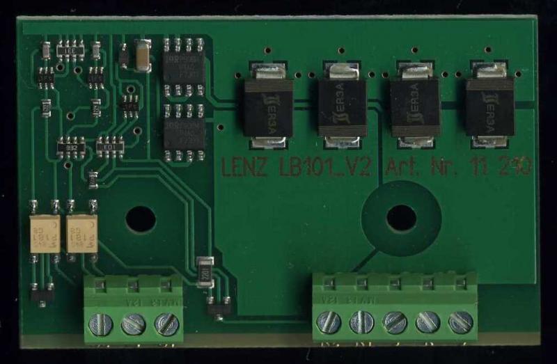
Does that help?
Max
Port Elderley
Port Elderley
Posted
Inactive Member
As soon as the first pair of wheels touches the track, it goes pink.What happens if block 4 is unoccupied at the start? Does it go pink with first pickups or last?
Max
Port Elderley
Port Elderley
Posted
Guest user
Posted
Full Member
In reality i guess it's an unintentional by product of the S88's unless Herr Freiwald und Herr LDT have der secret discussions im der fatherland, which they may have had, as most of the hardware is designed for programs like TC to use.
I shall continue to use my VD in favour of the VC.
Regards
Pete.
ECOS2 with RR&Co Traincontroller and a load of other electronics so i can sit back and watch the trains go by.
Pete.
ECOS2 with RR&Co Traincontroller and a load of other electronics so i can sit back and watch the trains go by.
1 guest and 0 members have just viewed this.