Petermac's baseboards
Posted
#4308
(In Topic #571)

Full Member
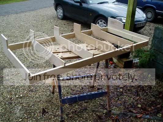
Basically, it's a sort of "open-top" with the trackbed being raised 35mm above the sub frame. The idea behind this is that (at some later stage) I want to run at 2 levels. I can therefore drop 1 track by 35mm whilst raising the other by the same amount giving my clearance in half the usual distance.
There will be 2 boards like this - each 5ft x 2ft 6" covering a station. The layout will extend into open countryside on each side - cuttings, tunnels and bridges spring to mind.
The sub frame (glued and screwed) is 70mm x 22mm, the risers are 10mm ply, the track bed is 10mm chipboard and the former at each end of the boards is 15mm ply for added strength at the board joints. As you can see, the 2nd piece of chipboard has yet to be cut and placed. The trackbed is screwed to the 10mm ply riser and should be self-supporting between the risers so that point motors etc. can be fixed/accessed below without too much difficulty.
Petermac
'Petermac

Posted

Legacy Member
Are there supposed to be pictures Petermac?
Posted

Full Member
Isn't that a well-worn line from Railway Modeller :?: :!: :wink:Petermac said
As you can see
Methinks the pictures are in limbo :!:

Posted
Legacy Member
Posted
Full Member
What did I forget ? I'll have try to get photobucket to do as I think !!!!

Hope this workds !!
Petermac
'Petermac
Posted
Full Member
Petermac
'Petermac
Posted

Full Member
One thing concerns me a little though; it appears that you have screwed through the framework directly into the 'end grain' of the plywood risers. Is this going to hold strongly enough? :? From previous experience I know that a bit of twisting or sideways pressure on a joint of this type and the ply laminates can start to split apart. Have you considered glueing some small reinforcing blocks to either side of the riser ends, perhaps?
Perry
Due to cutbacks, the light at the end of the tunnel has been switched off.
Posted
Full Member
The ply risers are screwed to softwood cross members the same size as the sides. Just doesn't show up in the photos. The next 1 will show the framework before the risers are fitted and you'll see what I mean. The trackbed is screwed into the ply riser but also with the odd blob of glue but thanks for the warning. Maybe I should use "blocks" for the trackbed fixings as well.
Petermac.
'Petermac
Posted
Full Member
Blocks on the trackbed fixings sound like a good idea too. It might make for more work at the outset but should give you a stronger, more stable, base in the long run. :)
Perry
Due to cutbacks, the light at the end of the tunnel has been switched off.
Posted

Full Member
glad to see you are making progress, feels good doesn't it

Are you going to put holes in your ply frame to allow your wiring to run through?
Posted
Full Member
Marty - Yes, it really does feel absolutely wonderful to be making a start !!! My problem will be rushing things. I've purposefully made myself think first so that, hopefully, when I start laying track, all will be mainly well. You'll see from my "Layout" thread that, already, I've discovered that my planned pointwork simply won't fit.
Re the holes for the wiring - yes, I plan to make 3 in each riser - 1 for feed, 1 for return and a third for "accessories" such as point motors and, if I ever get around to it, working signals plus station lighting etc.
Thanks to you both for the "nudge".
Petermac
'Petermac
Posted
Legacy Member
Posted
Full Member
Robert said
I would add a couple more holes if I were you. It's amazing how few wires it takes to make a thick bundle.
….or change to DCC, then you'll only need two wires!! :roll:
Seriously though, that's sound advice. Extra holes can help to keep different circuits well apart too making fault-finding easier. (Not that there will be any faults, of course! :roll: )
Perry
Due to cutbacks, the light at the end of the tunnel has been switched off.
Posted
Guest user
cheers Brian
Posted
Full Member
henryparrot said
Petermac the extra holes will allow your local mouse to get round easier plus you can use the holes as a coffee cup holder if you have a hook through it
cheers Brian
OK chaps - it's more holes - it'll make the boards lighter anyway !!
Re the DCC - I really would like to go down that route AND I know it makes sense in my position - still thinking hard - not quite decided yet. Maybe I need another shove.
Petermac
'Petermac
Posted
Full Member
There you go. :roll:
Oh yes, and Brian? You need to get out more! :roll:
Perry
Due to cutbacks, the light at the end of the tunnel has been switched off.
Posted
Guest user
Posted
Full Member
Matt - I think you're right !! Been here before but constantly hover. But seriously, I do think you DCC boys are right and it's almost certain I'll join you. Just have to find out how to convert 2 DC locos to DCC and buy a cheap controller from Hattons. :roll:
Petermac
'Petermac
Posted
Full Member
Installing DCC decoders sounds daunting (and I avoided the subject for a while because I didn't feel I knew enough about electricsPetermac said
Just have to find out how to convert 2 DC locos to DCC and buy a cheap controller from Hattons.
 ) but it's reasonably simple with a good set of instructions (and there are many of those online, pardon the pun), a hot fine point soldering iron and a steady hand. Oh, and a glass of something cheering to sip as you test the locomotive for the next hour or so. :wink:
 As for DCC systems, the prices are coming down all the time. Hattons prices look good, but shop around.
Posted
Full Member
Phill
1 guest and 0 members have just viewed this.