Installing Gaugemaster Seep Point Motors.
Posted
#3353
(In Topic #486)
Guest user
What follows is the method I used to install my seep point motors on PickWick.
I have used ideas I have seen and read about to work out a system that suits me and is easy to do. I am sure there are other ways…..but this is how I did it and I hope may prove usefull to others.
Step 1: The gaugemaster PM1 seep motor that includes internal switching. (I use the internal switch for the Peco electrofrog feed)
The motor is placed in a jig I have made from a scrap of 3x1 timber and a couple of old broken drill bits (Como or other micro drills) to use as pegs to hold the motor in place using the mounting holes. Photos below…
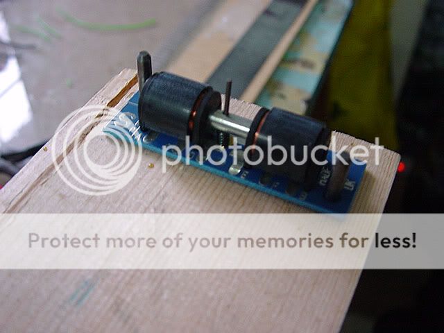

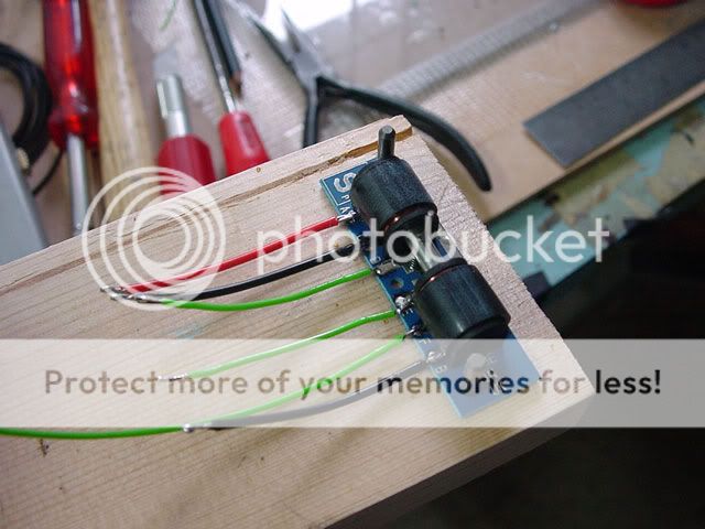
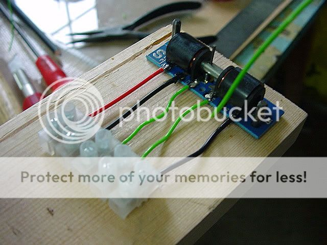
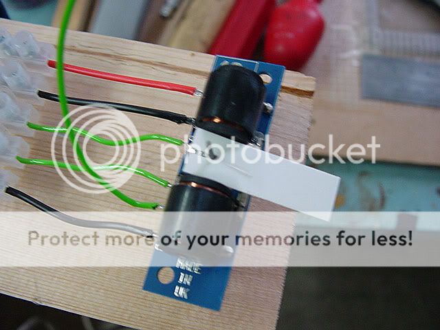
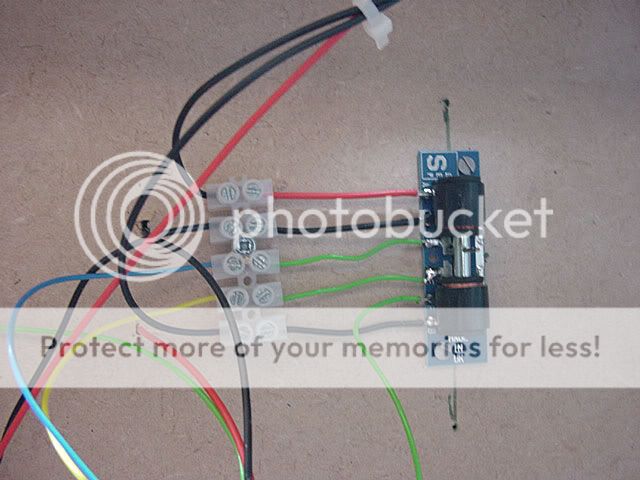
Step 2: Once I had my jig and motor in place the first thing needed is the tags on the motor are all soldered and require tinning for the short feed wires I use to connect the motor to a choc block for further connections.
Reasons for the choc block are two fold. One it is very easy to replace a defective motor in the future and two, mounting the motor first then allows easier wiring to the choc block rather than trying to solder upside down to the motor under the board.
Photo's below show the process of the feed wires, soldered tags and choc block assembly. Apologies for some of the poor soldering due to me taking photo's rather than thinking what I was doing… :? I sure yours will be better :)

Step 3: Now we have our sub assembly made with the point motor and connecting block, we need to mount this to the point from under the base board.
To aid alignment for the motor drive rod with the point throw bar I simply mark and drill two small holes in line and either side of the throwbar from above.
These along with the large center hole for the operating rod can be joined via marker pen under the baseboard to give a line to aid alignment. See photos below..

It is important to mark the center of the point throw bar as you will see later and this is simply done by wedging the point rails via small bits of scrap card etc so it holds in the center of its travel.

It is also desirable to hold the seep motor rod in the center too so as to make everything a little easier to line up….simply a small card or plasticard piece the width of the gap between the solenoids and a 1mm slot for the rod does the job nicely.
Step 4: Ok we have our motor aligned and our point throw bar also aligned….now a third hand is usefull for the next step or as I did you can use a bit of sticky tape to hold things…. :D
We need to offer up the motor under the board and insert the drive rod up into the point throw bar from beneath till the motor is flat against the bottom of the baseboard.
While we hold the motor central and inline we can mark the mounting holes in the motor pcb plate to drill for pilot holes for screwing down the motor.
Once these are marked we can drill and screw the motor into place and hopefully it will all still be central and aligned in the middle each items throw distance.

Step 5: Ok…still with me?
Right we now have our motor mounted below and joined to our point via the rod through the throw bar. At this stage we can release the card jig's from both the pooint and the motor and check for smooth operation by hand with the motor rod moving side through the solenoids and in turn this throwing the point above.
The Peco electrofrog points I use have a central spring and as such have their own latching at the extemities of each side to hold the point blade against the stock rail. The motor rod simply moves the throw bar across the center point and relies on the internal point spring to latch.
The Seep motors are available with latching so if you are using hand made rail and point work the motor is able to latch the blades for you.
Once happy we can wire up the feeds to the choc block and test…. :D
In my example as I am using DCC for my track but wanted to use a conventional point motor operation via A/C and toggle switches meant I needed to switch the rail supply for the frog feed across the internal motor switch but supply to the motor solenoids is via a seperate 18V A/C supply.
The various wiring options is covered by the documentation supplied with the Seep Motors and your DC or DCC system and is not covered here.
Step 6: Ok….all working correctly?
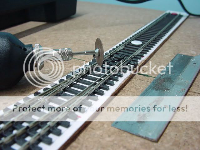
If yes we can trim off the excess motor throw rod length so we can run our locos and stock around.
The rod is over length to aid different mounting options and needs to be trimmed back after install. There are various ways to do this…the photo's below show some options… 1. Heavy duty side cutters 2. File 3. Saw 4. Cutting disc in a micro drill tool.
I took the 4 type as I have one but all will work……obviously precautions against sharp flying bits of steel rod/wire need to be taken.

Hopefully you have now mounted/wired and tested your Seep Point Motor and are enjoying the delights of changing your points via a switch or DCC not by 'the large hand from above' :D
Any comments are welcome or suggections regards alternate ways or tips.
Posted

Legacy Member

Posted

Full Member
cheers
Posted

Inactive Member
Very many thanks. :D :D :D
Les
Devon Junction
Kernow Junction
Kernow Junction
Posted
Guest user
Thanks for a clear and well illustrated guide Tony :!: :wink:
Posted
Full Member
When using a cutting disc on motor tool to cut the leftover bit off the extension to the throw arm make sure you use a heat sink (pair of pliers holding the waste bit) or take it easy.
If the cutting action heats up the extension arm too much it can melt the plastic tie bar on the points…. and then the point is ruined.
How do I know this :shock:

My friendly hobby shop owner is going to be happy to see me again. Sigh
Posted
Guest user
Marty…..good point! I used a carbon cutting disk on the Como drill and held the wire….did not get too hot at all as it's so quick but maybe other devices may be worse….I was pronbably just lucky :D
Posted

Full Member
That's a 'How To' in the very best traditions of this forum. An excellent piece of work. Thank you. :D
Perry
Due to cutbacks, the light at the end of the tunnel has been switched off.
Posted

Full Member
Thanks A Lot!
Wayne :D :D :D
Posted

Full Member
 For once, Wayne, this isn't one of Perry's masterclasses - but somone else's :!: :!: :wink:

Posted
Full Member
VERY WELL DONE Tony!
Thanks A Lot!
Wayne :oops: :oops: :oops: :oops: :oops: :D
Posted

Full Member
I think, when I get that far, I may just come back to this thread and have a go. :wink: :wink:
Petermac
'Petermac
Posted

Inactive Member
Thanks for your time and effort in putting this together.
Happy Modelling,
Mike
Mike
Posted
Full Member
Done that so many times with flexi track, MartyMarty said
it can melt the plastic tie
Sometime I still forget - but at least it's not as expensive a mistake as on a turnout :wink:
Posted
Guest user
Easily done as Perry add's so much great stuff for us all….glad you enjoyed the post.
Posted
Full Member
I notice you seem to have a laminated track bed !! Am I right in thinking you have:
1. Overall cork mat
2. Cork track bed
3. Polystyrene veneer.
If so, why ? Does the polystyrene make a huge difference to sound/cushioning of trains etc.
Petermac
'Petermac
Posted
Legacy Member
Posted
Guest user
1. Cork tiles base surface
2. Cork tiles cut to dimensions of raised track bed to provide shoulder.
3. XTrkad printout 1:1 scale for track layout. (paper)
Above is the formation you see….originally I was going for manual point control so the extra base layer would provide the 2-3mm for the wire in tube control.
The two layers of cork do however make for quieter running so far…when solid with ballast we will have to see.
Posted
Full Member
Petermac
'Petermac
Posted
Inactive Member
Today I built a test rig and wired up the seep motor to a peco streamline code 100 point. It switches ok but I am getting an annoying buzz on each throw which I don't get when the motor is tested free of the point. When I look more closely the "throw" of the seep motor is quite a bit longer than the peco equivalent and the peco point. So, it appears the point is restricting the length of the seep motor throw and, I think, causing the buzz as the coil is still trying to pull the solenoid but being stopped by the point. If I take the seep motor off and limit the throw with my finger I get a similar buzz.
Have you come across this problem and, more importantly, have you any suggestions on how to overcome it?
Cheers, Mike
Happy Modelling,
Mike
Mike
1 guest and 0 members have just viewed this.