Layout for Dad
Posted
#82634
(In Topic #4565)
Guest user
OO 9' x 9' roundy roundy layout baseboards
Layout for DadI thought I would put this here, it is the story of a project that has been hanging around for a number of years which I completed last year.
I promised my Dad a good while ago I would build the baseboards of a layout for him, a number of my own layout builds and a house move later, I finally got round to doing something about it.
Brief was simple, roughly a nine foot square room needing a roundy roundy OO layout to watch the trains go by with a bit of shunting to add some interest.
This is the basic trackplan.

I am a big fan of plywood and did some early experiments with 3mm ply.
Testing a 3mm sheet for weight support.
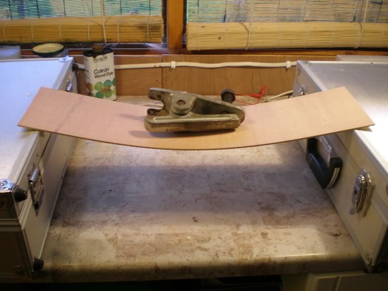
The same weight but the ply now has some half inch timbers glued on.

Basically a wooden girder.

This gives good strength from a very light timber construction, I may include this in some of the boards.
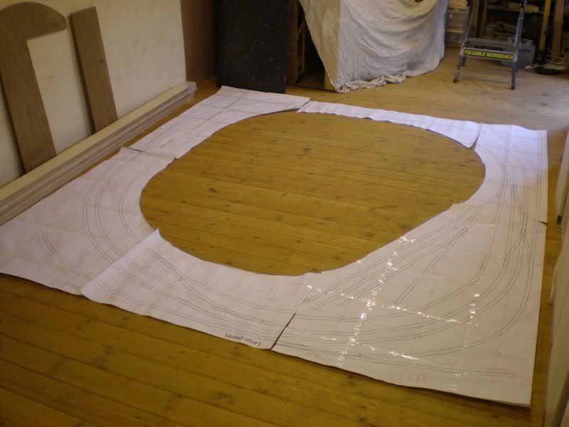
I drew the track plan on a Mac using Adobe Illustrator to give me a file I could print out full size on A3 paper and tape together to give me a pattern for the boards and to test it fitted the room.
A close up of some of the plans.

The whole layout plan in my shed before constructions begins.
I ordered an 8 x 4 sheet of 9mm birch ply cut as 100mm strips, this would form the main side panels. The end panels are 12mm ply to give something larger to attach to.
Infil cross bracing will be with 3mm ply and 2 x 1 spacer blocks. Track bed will be 4mm ply probably covered with cork or maybe thin foam.
This is the 9mm ply.

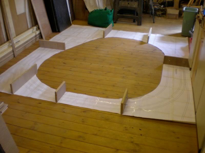
I managed to cut all the end boards from one bit of four foot square 12mm ply.
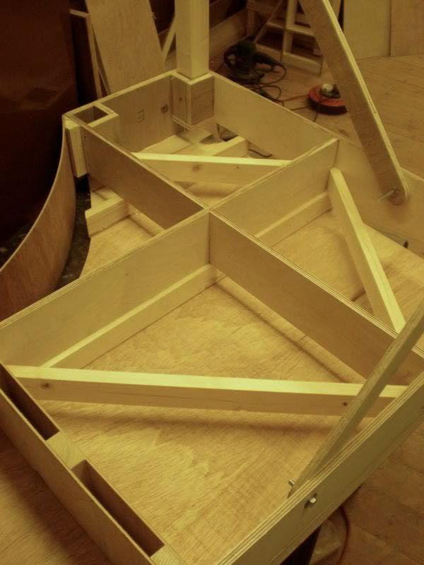
These are the end boards placed in position on the plan, all were drilled in pairs for bolts and alignment dowels to ensure they matched exactly.
Drilling with a bench drill to ensure accurate vertical drilling, note the Tee nuts and bolts are already fitted prior to drilling for the brass dowels.

These are the brass dowels before final tapping home.


One of the boards after initial construction.

More to follow.
Martin
Posted
Guest user
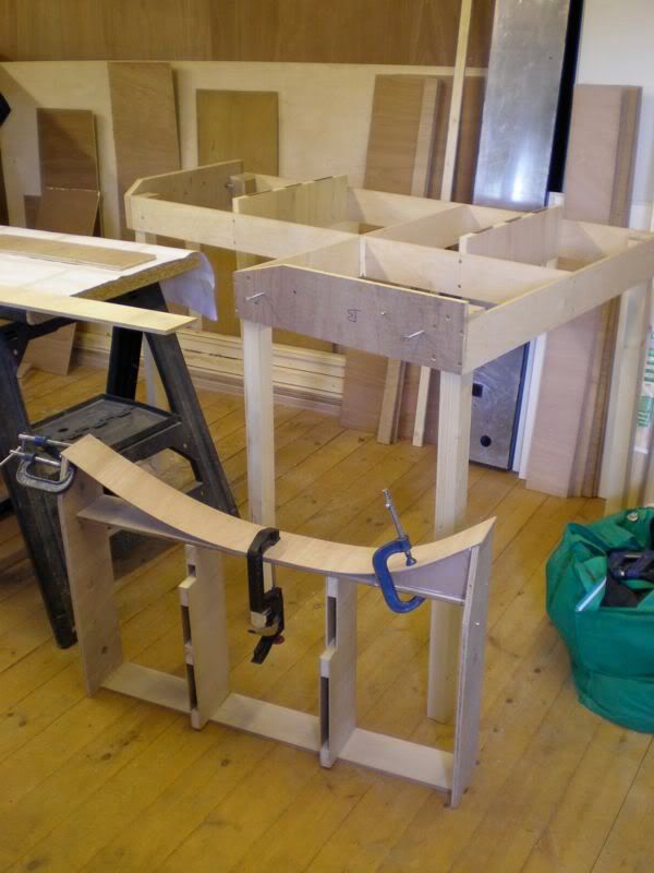
With an infill for strength.

Two boards with a curved front checking alignment.

First support leg mocked up for fitting.
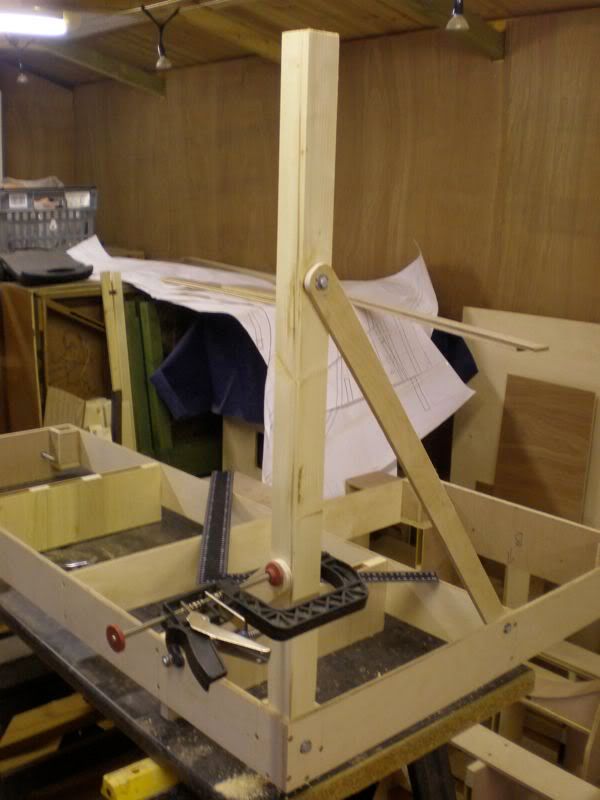
All bolts located with TEE nuts here shown in position ready for tightening.

A bolt inserted for tightening the nuts.

Fully finished.

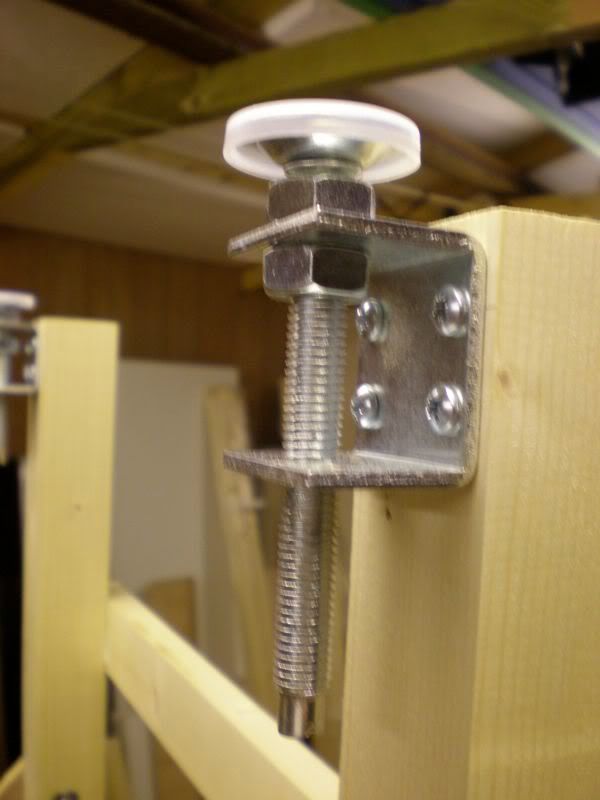
One corner board fotted with the three legs.

Each leg has one of these adjusters.
Now starting to take shape.
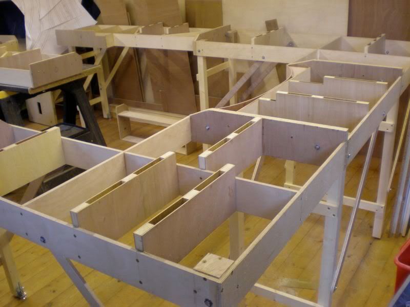
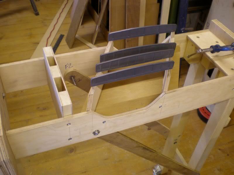
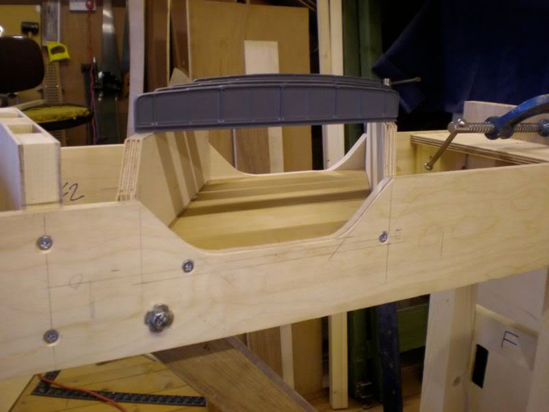
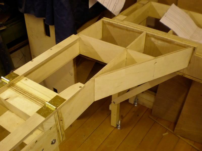
This is the bridge section just before the lifting flap.
Just the lifting flap to go then I will have a complete set of basic boards.

Martin
Posted
Guest user
This is it in place.
This is it partially raised. The hinges are mounted above rail height so that board effectively lifts before hinging otherwise the rails would hit.

Also managed to fit the remaining cross braces, it is amazing this simple addition has made.
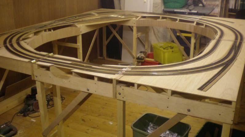
The layout had a slight amount of movement without them, now it rock solid and that is without the baseboard top or bracing for the curved front panel.


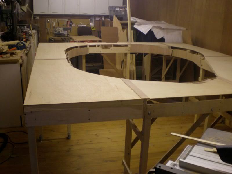
This is a shot of the entire layout as it now stands. Hoping by next weekend to have all the track bed in place.

Martin
Posted
Guest user

Stuck the track base down on the bridge section having cut a gap to separate the single and double row track.

Mocked up some track, bridge sides and stock to see what it would look like.
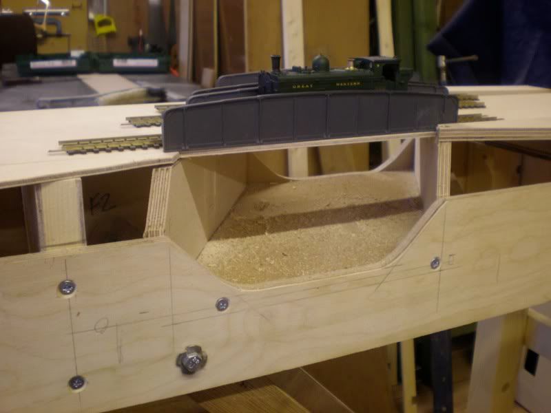
The bridge sides look close in the picture because I have placed them on the board rather than stuck on the side of the board.

Having a full size track plan helps with marking out the ply for cutting.

Track base ready to be stuck to the next board.

A close up of a pair of leg sockets.

The same sockets with the legs inserted.

Martin
Posted
Guest user
Another section with the ply top now fixed in position.

Now fixing some of the curved front panels.


A view underneath of one of the boards with a top fixed on.
Finished putting the bracing bits in for the board that receives the hinged section.

Just have to finish the tops and front panels and drop in any bracing where I feel necessary while avoiding point motor locations. I need to order some cork sheet to lay the track on.
Martin
Posted
Guest user
I glued in some pieces of 3mm ply on the cross braces to support the top boards better, surprising what difference this small addition made.

Once all the ply tops had been fitted I then added 3mm ply end strips at all joints, this will give a much stronger butt joint surface rather than the cork, which I feel might chip. Will also be a better surface to fit the paxolin strips for the track ends.

Then the cork can be laid right up to it.

All the ply tops are now in place, a few front panels to finish and glue down the cork.
Martin
Posted
Guest user

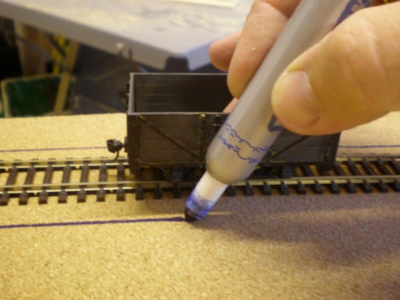
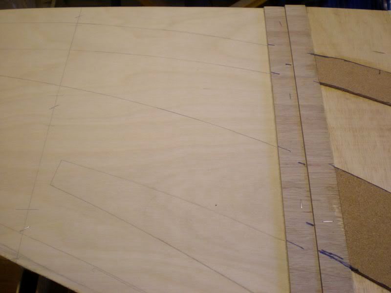
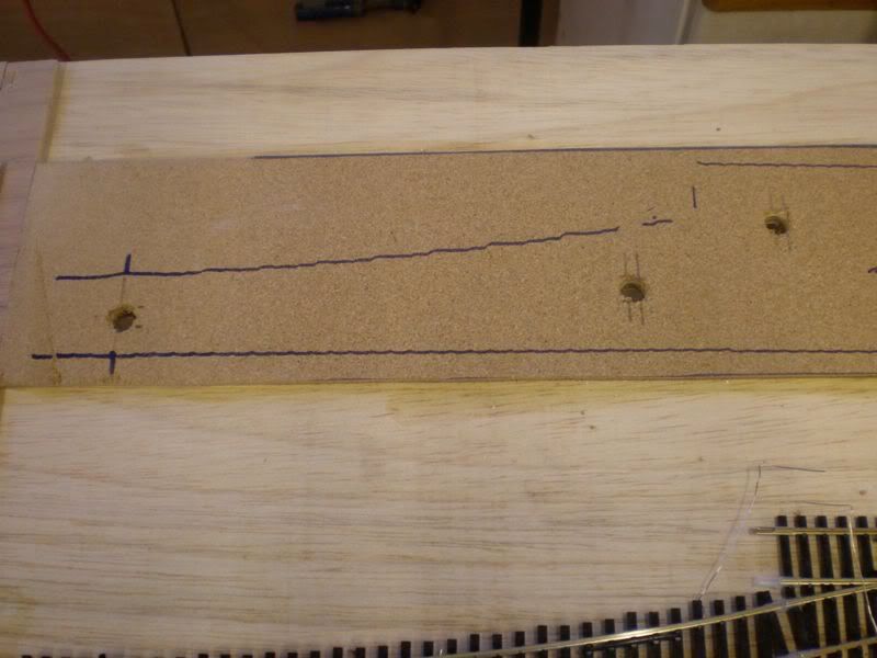
A wagon is placed on the track and pushed while holding a pen to the side drawing a line parallel to the track as a cutting guide.
Alternatively a thin piece of timber can be used as a guide as seen here, this piece was one left over after shortening a wooden venetian blind.
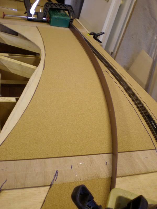
Once all the guides were drawn in the cork was cut to shape.

This was outlined in pencil to show where the glue should go, they just show in the picture.
PVA glue was poured and brushed in place.

Cork is then placed in position and rolled flat with one of these.
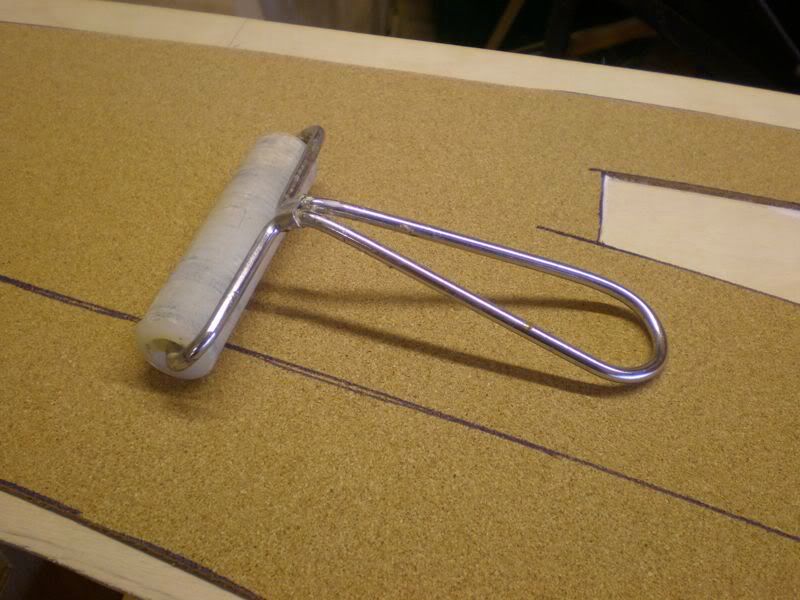
Then weighted until dry with bound copies of BRM and RM, I knew they would come in handy one day!

Just the copperclad at the board joints to do, then the first circuit of track can be laid, then it is off to it’s new home.
Martin
Posted
Guest user

I had some copperclad sheet in stock, so cut it into strips on the mini bench saw.
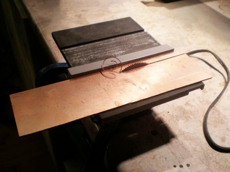
Which ended up as these strips.

These were then cut to length, drilled and pilot hole drilled the boards to accept brass nails, the copperclad strip was glued as well, so should hold quite well.
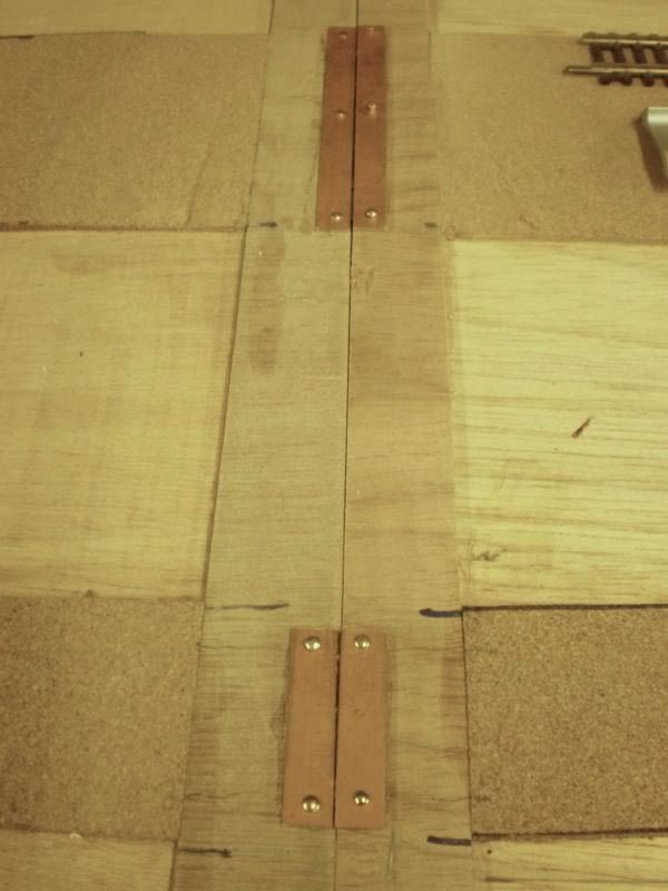
Only a couple more board joints to finish then track laying can begin.
I ordered the points today, now £180 less in the pocket :roll:
Martin
Posted
Guest user
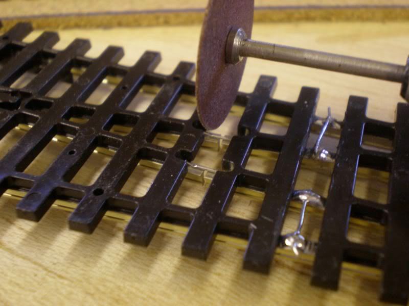
I also modify the switch end by removing the motor mounting lug holes and the lumps at the end of the tie bars to try and disguise the Peco look to the points.
Before …..

…… and after
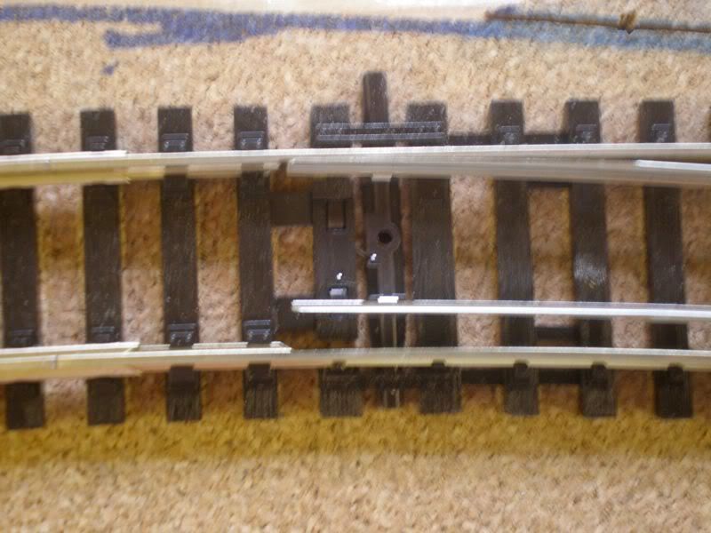
Positions are marked to drill the hole for the point motor shaft and the frog wiring.

Then a 10mm drill does the job.
I use Copydex to glue the track down. I like this glue because it stays flexible, not rock hard like PVA, which means track can be lifted without damage. The ballast is also fixed with Copydex diluted 50/50 with water a few drops of washing up liquid.

Track across baseboard joins is soldered to the copperclad, very thin dummy sleepers will be glued on later to disguise the join. Track is then cut with a slitting disk.

I don’t know why but I always seem to work in a mess, I must have a tidy up.

Martin
Posted
Guest user

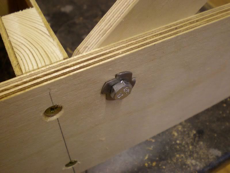
There is a second bolt above the one at the top of the picture, these bolts give good vertical and lateral alignment, but not 100% perfect. I will be using these to bolts to take the track power (DCC) to the last 18 inches of track on the adjoining baseboard, this is for safety of the stock. When the panel is up, power will be disconnected from the last 18 inches of track so engines won’t run off the edge, hopefully, unless of course they are reversing a train or going very fast!
The adapted mirror plate at the bottom of the picture is there to pull the boards together and gives perfect alignment. Basically it pivots round the big screw on the left and locates on the screw on the right, I have cut a slot so it acts like a cam when it locates on the right hand screw.
The bolt at the bottom acts as a handle, probably better if I had photographed it open as well.
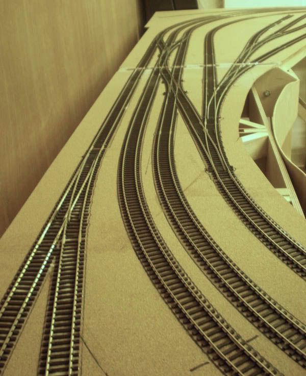
This is the throat and bay platform road of the station.
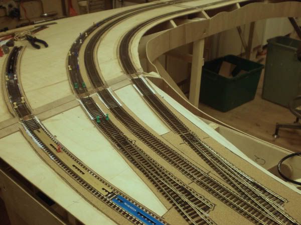
The same throat from the other direction with track laying approaching the next baseboard joint.

This is a view from the other end of the station showing the crossing and the factory siding.

Here we have the main crossings and the start of the main goods sidings. The far end eventually curves to the right to meet up with the station throat.

A general view of progress to date.

Martin
Posted
Guest user
Some overall pictures of the complete layout.

The main crossovers with the goods yard to the right.
Station through crossings with engine shed road in the background.

This is a view of where the station platforms go with the bay platform road in the foreground.

The factory siding in the opposite corner to the station.

Tracks over the bridges on their way to the main junction.

Thats all folks.
Martin
Posted
Full Member
Phill

Posted
Guest user

Now this photo
The wagon - Kadee with no buffers - please explain ?
as I too are going that way

Posted
Guest user
Very simple, this is an old 7mm narrow gauge wagon I had kicking around and was using it purely to hold the pen while tracing where to cut the cork.Not bad for a days work Martin
Now this photo
The wagon - Kadee with no buffers - please explain ?
Martin
Posted

Full Member
Looking at all that cross-bracing and a solid top, I wonder why you used ply for the framework ? Was it to avoid any warping associated with softwood ?
One or two of us (including me) use the ply girder system ("a la Barry Norman") but have found it does flex quite a lot and needs cross-bracing. To me, this does defeat some of the advantages of ply - particularly given that, here at least, it's a fair bit more expensive than softwood.
'Petermac
Posted

Legacy Member
Bozzy(never known to pass a pub)
Posted
Guest user
Although I bought some ply I did have loads of 3mm in stock, over 400 pieces 6" x 58" which is one of the advantages of having a brother who used to work in the board industry.Good looking woodwork Martin. :thumbs As Sol said - not bad for a days work !!!!
Looking at all that cross-bracing and a solid top, I wonder why you used ply for the framework ? Was it to avoid any warping associated with softwood ?
One or two of us (including me) use the ply girder system ("a la Barry Norman") but have found it does flex quite a lot and needs cross-bracing. To me, this does defeat some of the advantages of ply - particularly given that, here at least, it's a fair bit more expensive than softwood.
The solid tops are 4mm ply, the cross bracing was to stiffen the whole structure, this worked well because there is no twist whatsoever in the boards.
The boards are very light, even the biggest board can be picked up single handed.
I like working with plywood (good quality stuff), saves a lot of time compared to trying to find straight timbers these days at the local DIY sheds.
The whole project was started in mid July last year and the layout was installed at my Dad's very early October, actually it was on his birthday.
Martin
Posted
Guest user
Thank you, no I did do woodwork for A level learning cabinet making and also had two years working for my Father-in-laws building company working with carpenters, I learnt more in the first week with these guys than I did in two years at school!Those base boards are amazing were you employed by Mr Chipendale in a former life, thats the furniture makers not the dancers by the way.
Martin
Posted
Full Member
I agree Martin - there's absolutely no substitute for practical experience. :cheersThank you, no I did do woodwork for A level learning cabinet making and also had two years working for my Father-in-laws building company working with carpenters, I learnt more in the first week with these guys than I did in two years at school!
Martin
I wish I had a brother like yours……………….:roll: I shudder to think what use I could make of my brother's "industry" in my model railway !!!
'Petermac
Posted

Full Member
I've been through the whole thread.
Hope this is preserved for posterity and those starting a new layout.
Always something to learn.
1 guest and 0 members have just viewed this.