N Gauge - Newcastle Emlyn****
Posted

Full Member
…..Closer inspection shows that I have miscalculated with one of my risers and I'm going to have to break the glue bond (no nails or screws used) and jack it up a little bit to get a smooth slope.
Could you perhaps add a small sub-riser to the one already in place to save breaking it off?
Perry
That looks like a really interesting plan, Marty. And I like your benchwork - build it substantial, that way it can't be removed easily
MikeC

Posted
Full Member
Perry,
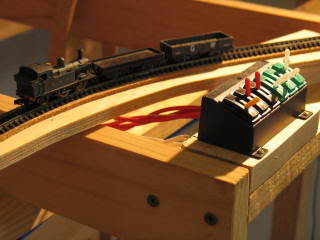
The riser in question, see photo below, is more a spacer of 9mm ply tucked between the roadbed and the baseboard and glued. No choice I'm afraid but to pry it apart, gently, if at all possible, and add something to it to get the grade even.
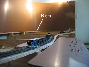
The photo also shows the track and points in place for Riverbank Siding and the Quarry with the local goods behind a 45xx Prairie Tank waiting in the loop while the 14xx and it's autocoach head towards Henllan. There are a couple of lime wagons in the quarry in the distance.
The test control panel on the right is temporary and allows me to do some real shunting
PS Sorry about the size of the photo, I think I got the camera settings wrong.
…and I've found the section on timetable operations on the Barchester Site Bob. I'll have a read of that and mull it over while I think of the operating plan for Newcastle Emlyn.
As I said before, I don't envisage having anywhere near the number of movements per day as Barchester but then, I've got a lot further for each movement to go to
Bob replied�
You're right there Marty. For all Barchester's overall length of 24' there isn't a great deal of actual visible running length. It's in the nature of that type of layout. Hence the extremely busy schedule. I make up for lack of running length with multiple train movements.
Posted
Full Member
I've just been reading about your problem with the curved point. One thing you might like to check which isn't always immediately obvious is that the point is actually flat from side to side. I once had one that had a high spot in the middle - near the frog - and it caused all sorts of trouble until I realised what was doing it. A straight edge across the frog from stock rail to stock rail should show up any discrepancy.
Good luck.
Perry
Posted
Full Member
I've tried the other Farish and Dapol loco's and they all negotiate the points without any trouble.
I'm sure it's a combination of the long rigid wheelbase of the tank loco and the way that the point is constructed. I've bent the contact rails (the moving ones) a little bit and have reduced the amount of shorting and derailing a little but at anything more than a crawl, either forwards or backwards 50% of the time they will derail.
When running towards the toe of the point they come off just where the contact rails join the stock rails, there is an almost imperceptible bump that lifts the flange above the rail and off she comes. But only some of the time, it's weird.
When running towards the left hand rail there is a little bump over the leading edge of the frog and off she comes, once again only 50% of the time.
This is all light engine.
When hauling a load, the percentage of derailments drops to about 20% of the time, I guess that the string of wagons help guide the loco through the points.
When I get the chance I'll have to put the magnifiers on and sit up close and watch closely to see if I can work out what is going on.
It's a bit of a disappointment actually as I don't want to get on with the layout until I get this resolved. There's no fun in it if they keep coming off.
While I was testing I tried double heading the two 14xx on a goods of about 9 trucks and brake van and they managed to climb from riverbank sidings up the 1:45 hidden loop without too many problems. I hadn't planned for a banker to be used but it adds some more interesting operations to the layout. The banker would only be needed on the climb up to Pencader from Newcastle Emlyn so I guess that fits in with the prototype.
Mind you the brake van derailed on those blasted points
Posted
Full Member
The riser/spacer in the picture above came apart neatly and sweetly with a bit of leverage from the biggest screwdriver I own. Half an hour of running trains up and down the grade that the riser supports allowed me to fine tune the slope so that it is uniform along it's entire length.
With the grade a nominal 1:45 the weakest Dapol 14xx that I have can manage it's B-set of 2 coaches without too many problems, but any more than about 5 vans with dirty wheels brings it to a wheel spinning halt.
The Dapol 45xx manages at least 9 vans/tanks/wagons and the Farish locos all seem to be able to handle it without getting their hair mussed.
The PECO point from hell has just about been tamed thankfully because its problems were a huge disappointment. The point served the quarry siding from the branch and having loco's derail every time they went past just wasn't what I had in mind.
I had to get the 4 x magnifiers and a bright light on to help me see what was going on and run the 14xx tanks up and down at various speeds, forwards and backwards, cab first and tender first until I worked it out.
Light engine, tender first at any speed above a crawl the trailing wheels under the tender dropped off the inside rail and onto the sleepers between the rails, then, as the loco continued on towards the toe of the points, the gap between the inside stock rail and the outside point rail closed in again, squeezing the wheel set until it popped up like a watermelon pip between your fingers. The pop being big enough to throw the wheels off the outside rail and into the dirt.
To me, it looks like the points were out of gauge. I don't have a n scale track gauge but I'm going to get one. I don't think it was the loco trailing wheels because it happened to both 14xx's and the 45xx that I have.
So, a couple of quick cuts with the craft knife separated the inside rail chair from the sleeper and about an hour was spent adjusting the inside stock rail until all my locos negotiated it without derailing.
That required a fair bit of running up and down with and without wagons/coaches I'm going to mount the point motor to it and see how it goes in general running over the next couple of weeks.
The last hour or so of Sunday evening had the permanent way crew doing overtime getting another length of track down on the return loop bank behind Riverside siding. This part of the line now extends to the baseboard join of boards 1 & 2. There it will stop until I get the Henllan station built as it is better to build the bank up to the flat of the station rather than try and get the station height to match the top of the bank.
A bit of wiring underneath to extend the common return wire and connect up the new bit of track, 10 mins or so of some "testing" again and it was time for bed.
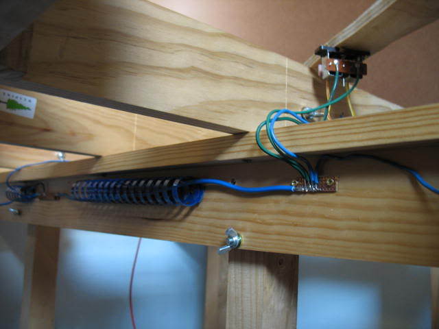
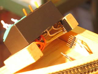
Not the bit I worked on last night but shows the general idea and how I'm wiring up my points too.
Posted
Full Member
Sounds like sorting that troublesome point out was a bit of a task! Still, you seem to have found a few 'excuses' for running some trains anyway.
The wiring certainly looks neat. Do you colour-code or number tag your wiring to make future modifications or fault-finding easier? (Not that there will be any faults, of course.
Perry
_________________
Posted
Full Member
A couple of minutes work with the dremel tool and an engraving bit and we were away again.
The wires are colour coded.
Blue = common return and power return from the rails
Red = power to the rails from power pack and control panels
White = point motor common power to push buttons
yellow (with various stripes) = point motor power from push button
Green (with various stripes) = point motor return power to common return.
I haven't numbered or "mapped" the wiring yet although I do plan to. My eldest son is an apprentice sparky and I'm hoping he'll lend a hand. He's also useful for providing scrap wiring that is no longer needed at the workshop. I've got enough red to last a lifetime.
The other colours are from various sources, most of it stripped out of my first car after I rolled it and wrote it off on a country road outback 20 years ago. I scrapped it myself on my mum's front lawn and carefully rolled all the wiring harness up and put it away in a box for the railway layout that I knew I was going to have one day. Other bits are from house wiring from the renovations T and I did a couple of years back and some of it is from the renovations that my company did to it's offices earlier this year. GWR would be proud of me
Trouble with finding excuses with running trains is that they seem to be very easy to find and that eats into the construction time
cheers
Marty
 Last edit: by Marty
Posted
Full Member
Planning for the start of the Henllan station goes on in my mind and I'm running milk tank trains up and down the existing line that I have to prevent withdrawl symptoms. cheers.
Marty
Even thinking about what you're going to build can help to keep the interest level high though. I find that if I take enough time to think about things before I even commit it to paper, I can come up with better ideas than the original one and also possibly become aware of snags that weren't previously foreseen (like my turntable not fitting, for instance!).
You'll get there in the end, Marty.
Best wishes,
Perry
It always comes down to priorities Marty and some things just have to go on the back burner temporarily. As Perry points out though this can have it's advantages in future saved time, costs and frustration, so it's not all on the down side.
Bob
Thanks for the encouragement guys, have no doubt that I will soldier on… just at a walk rather than the post Christmas gallop.
Marty
Posted
Full Member
To speed things up I've dropped in some of the relevant posts from the other members as replies from me, but hopefully it still makes sense.
That's now all of my Newcastle Emlyn Layout Thread up to date from the old site.
Getting late, I'm still at the office and T will be wondering where I am.
A progress report on the layout in the next couple of days…
Posted
Full Member
I fiddled with it, reduced the gauge where I thought there was a problem, checked for uneven rails, altered the curve of the rails and tested, tested, tested. Towards the end even some of the rolling stock were derailing! Not just the Dapol 0-4-2 tanks. I was going backwards.
So… in desperation and convinced I was throwing good money after bad, I ripped up the old, twisted, out of gauge, unco-operative and basically naffed set of points. My friendly hobby shop owner was delighted, naturally, to see me once again and cheerfully handed over a NEW large radius, curved, left-hand set of points in exchange for some more of my hard earned readies.
I took the new points home and left them on the workbench for days, the brand new box mocking me every time I passed the layout room. I was hesitating, not wanting to be disappointed once again and thus forced to go back to the drawing board and redesign the whole layout without large radius, curved points. I'd planned to use a fair few of them too.
Eventually and mainly because I now had a gap in my running line and driving trains wasn't as much fun as it was before, I gathered up the courage and gingerly, carefully and with much fussing and faffing about eased them into place at the Quarry siding…
… and to my great relief they worked a treat.
The Dapol tanks do still get "trapped" once in every 30 or so trips but free themselves almost immediately and carry on their way. With or without wagons and either backwards or forwards, the right way around or bunker first.
I still have to mount the Peco point motor and it's throwbar which is going to take a bunch more of fussing and faffing but… and here's hoping, I think I've got it licked.
Posted
Full Member
20 years on and time for an overhaul
Somewhere in the old forum is a comment that I had received a cheerful email from Bob Russell from BR Lines in the UK confirming that overhauling old Farish locomotives was what they did and they were happy to have a look at mine.
That was in February this year� sigh, It fairly rockets past this time thing, doesn�t it?
Anyway, seeing there isn�t a lot of modelling getting done at the moment, what with work and life getting in the way, to satisfy the railway withdrawal symptoms there are little layout related purchases here and there, from time to time. Which, of course, require an occasional test run on the line that is operational.
The little Dapol 0-4-2 tanks get first go, because they are the most unreliable of my locomotives, one is allocated to the permanent way crew building the line for testing and it�s, well� ready to go. However, they are little and light and only manage about 4 to 8 wagons up the 1:45 bank and it�s not very long before the urge to run longer trains becomes undeniable.
So out comes an 0-6-0 and some more wagons, and then the 2-6-2�s � and a few more wagons� and then, when I should really be doing something else, the fact that my poor old Hall class tender engine is knackered and can�t be used miffs me a bit.
So, to cut a ramble short, the Hall
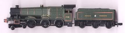

and a 94xx 0-6-0 in similar condition
have been dispatched, via airmail, to Bob for overhaul.
Posted
Full Member
Has anyone had experience with Peco's ON-ON passing contact switches?
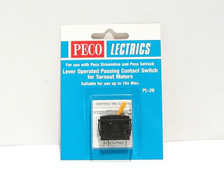
They are designed to give a momentary pulse of electricity to the Peco point motor.
I've wired one into the Quarry Siding points, threw the lever and nothing happened. I did a bunch of testing with my multimeter and all my wiring checks out, I can short past the switch with a bit of wire and the point motor works.
I wired in a second switch, a lot more carefully this time because I suspected that I might have left the soldering iron on the metal tag too long and maybe melted some of the plastic mounting inside the switch thus causing the mechanism to fail. However, after soldering the wires to terminal lugs and then sliding the lugs over the switch machine tabs and testing, the second switch didn't work either.
I don't understand, the only thing I can think of is that the switches are faulty but they are brand new from the friendly model shop yesterday.
The mechanism, as I understand it, is just a copper plate making momentary contact between the input power, about 14V DC, and the output lead to the point motor.
The wiring is exactly the same as I have done with my Push To Make (PTM) buttons on the Riverbank sidings control panel. The Peco switch is just a fancy PTM, looking like signal box levers.
Any thoughts, comments appreciated lads. I can do photos if that would help.
Posted
Full Member
Hi Marty,
Are you able to test the switch with your multimeter when it's not connected to any wiring? If so, does that show any switching contact being made across the terminals? A simple continuity check on the ohms setting is all you would need to try.
Perry
Posted: Sat May 26, 2007 10:23 pm Post subject:
Thanks Perry, I tested the switch as per your suggestion and it was passing current.
Therefore… it had to be my dodgy soldering… and sure enough it was. I hadn't bridged completely across the bit of circuit board I'm using to distibute the power feed to the switches.
Problem solved, well done many thanks.
Marty
Posted: Sat May 26, 2007 10:26 pm Post subject:
The getting it wrongs are just as helpful as the getting it rights to members who are learning, so that's a good one Marty.
Bob
Posted
Full Member
It's just the hobbies way of improving our soldering skills
All six switches wired up and operational. 3 for changing points and 3 for isolated track sections.
The Quarry siding point is now powered and Henllan Station is next on the list. Yippee.
The CAD plan was fired up last night for the first time in a while, I need to work out how big the sheet of ply is going to have to be for the station baseboard. Making progress.
Posted
Full Member
Can you show us a few photo's of your progress to date, perhaps?
All the best,
Perry
Posted: Mon May 28, 2007 9:25 pm Post subject:
Nothing of much significance has happened for months Perry but last weekend I was able to set aside enough time to tidy up the Quarry Siding points and wire up the Peco switches. So maybe that's progress but nothing much more to see than the Riverbank siding photo posted earlier.
I'll try and post a photo of the completed lever frame shortly.
I've been envious of your scratch building and baseboard progress but then you were being dictated to by circumstances beyond your control and there was no work to get in the way.
So, with some soldering lessons learnt from yesterday, the future beckons.
I'm pottering around with the CAD package at the moment, the proposed baseboard for the Henllan station is a weird shape, no rectangles here. Transferring the design from the drawing to the sheet of ply is going to take a bit of effort. Overall dimensions are 1105mm x 900mm but it's sort of banana shaped to fit in the curve of the station. The CAD package can give distance and bearing so there is going to have to be a whole bunch of distance and angle measurements from a fixed point drawn on the baseboard, then join the dots.
Then, measure twice, ummm, three times and cut once
Posted
Full Member
Riverbank and Quarry siding Lever Frame
Here�s the new lever frame wired up and in place.
The Black switches control points, yellow lever � Quarry siding, red levers � one for each end of the Riverbank Siding loop, Green switches control isolation sections in the Quarry, main line and loop respectively.
The Dapol 14xx 0-4-2 tank seen here is the one assigned to the engineers track laying crew. I�m actually starting to warm to it, the more work it gets the better it runs and the quieter it gets. Apart from the occasional �catch� in the Quarry points it never stalls either.
It still couldn�t pull the skin of a bowl of cold custard but they weren�t designed for more than light duties anyway.
A C shaped section of wood acts as a mounting block and provided a bit more room for the wiring and the connection points to be packed all neat and tidy under the frame. White and yellow for point wiring. Red and Orange for isolation sections. The connectors unplug so that the lever frame and wiring can be taken back to the workbench for modifications when (not if) they are required. 2 wood screws secure the mounting block to the shelf it sits on.
The location of the lever frame is temporary at the moment, it�s actually sitting in the River Tiefi. It might remain there, with the river modelled around it or it may be mounted on a control panel on the front of the layout somehow.
For, um… testing purposes… it�s fine where it is.
Posted
Full Member
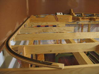
Henllan Station site
Well I guess it�s certainly a greenfield site.
This is baseboard 3 with the hidden loop line from Riverbank sidings to Henllan Station running up the grade next to the backboard.
The station will start about half way along this board and continue to the board break just in front of the controller in the distance.
Posted
Full Member
Just a quick query; do the type of plug-in connectors you have used for the lever frame cause you any grief? It may just be the way the photograph shows it, but it looks as though there are several uninsulated soldered joints in very close proximity to one another. Perhaps the distances between the connections are greater than they look. This is not in any way a criticism; just an observation. Is the gauge and type of wire you use perhaps rigid enough to stop accidental movement and therefore preclude any short circuits, or do you use any other means of safeguarding the connections?
I have yet to decide upon inter-baseboard and control panel connectors so I would value your comments on the type you have chosen.
Cheers,
Perry
Posted: Wed May 30, 2007 12:56 pm Post subject:
Perry,
All of the soldered joints are in closish proximity to each other and are uninsulated. I've experienced no problems so far. I was a little concerned about it myself but it seems to work.
The gap, in most instances is twice the diameter of the wire used, although there are a couple of different sizes used to get the colours I wanted.
I was careful to position the soldered connections in such a way as to maximise the space between them and minimise the amount of solder. Indeed, one of the joints had to be re-soldered due to too little solder. Where there was a solder "spike", a file has been applied to remove it.
The black casing is super glued to the wood and the whole thing, when connected together is solid. The pins are just push to fit and hold firmly and don't fall out, although, if used in a situation where they are constantly in use, this might change as they wear.
The connector was just something I had at the bottom of the electric bits box and as I too have yet to decide on the board connectors, I thought I'd give it a go.
For my money, the board connectors are going to be more rugged.
I started looking for options the other day when I was in the electronics shop, oops - geek alert, it's all hobby based really I promise.
At the moment 9 pin D-sub computer connectors are looking good, but I'm still looking. You can get up to 50 pin DD-50 connectors which should do for control panels. They are not cheap but you will only have to do it once.
D-subminiature - Wikipedia
cheers,
Posted
Full Member
Perry
Posted: Wed May 30, 2007 4:23 pm Post subject:
… and they should handle model railway voltage and current OK?
Marty
Posted: Wed May 30, 2007 5:47 pm Post subject:
The specifications I have for D-type connectors quote a working current of 7.5A per contact and a working voltage of 300V rms. All well over what we need. The only thing you perhaps need to bear in mind is the diameter of the cable you use; just make sure there is room for it all. I will use a multicore cable for these connections as I find it a lot easier and tidier for this purpose, but it's obviously a matter of personal preference.
Perry
Posted: Thu May 31, 2007 5:35 am Post subject:
Perry,I bought some D connectors recently (at a small model railway exhibition) in readyness for when I do my electrics.
One question … when I make the connections using my choosen wire, do I need to use heatshrink tubing to cover the soldered ends
Jeff
Posted: Thu May 31, 2007 11:47 pm Post subject:
You shouldn't need to. The places you solder the wires into are shaped like little 'cups' so the end of the wire pushes into them for soldering. Provided you don't strip too much insulation off the wire all should be fine. Also, bear in mind that the heatshrink tubing would add more bulk inside the connector body; something you can well do without.
Perry
Posted: Fri Jun 01, 2007 12:20 am Post subject:
Thought so, but just as well to check with someone who's used them before.
Thanks Perry.
Jeff
Posted: Fri Jun 01, 2007 8:06 am Post subject:
Sounds like Dsub connectors are the go then… I'll pick up a set over the next couple of weeks for testing.
Marty
Posted
Full Member
The Henllan Baseboard – KISS (do you really need me to explain this one?) priniciple.
After your comments earlier about the “banana” shaped baseboard for the Henllan Station layout and the difficulties transferring the shape from the plan to the plywood, the CAD plan was consulted at length and with the assistance of T and a glass of wine there has been a modification to the plan. Modification number two thousand and twelve maybe!!
Why make it more complicated than I have to?
The L-Girder framework and ribbon subroadbed construction being used on Newcastle Emlyn is designed, I hope, to reduce weight and hopefully make a layout more portable when (not if???) it becomes good enough to be offered up for exhibition.
As such, all baseboards for stations, yards, loops and sidings were planned to support track and associated buildings and have an extra 5cm’s around the edge to support the scenery. This has led to some interesting baseboard shapes and thus the difficulty.
It’s just not worth faffing about for the amount of weight that is going to be saved.
The Henllan Station baseboard is going rectangular and a trip to the hardware on Sunday for an appropriately sized bit of ply is proposed.
Why not go shopping on Saturday you ask?
Easy, the once a year Australian Model Railway Association (WA Branch) Perth Show is on this long weekend at the Claremont showgrounds and there are 55 stands, about half which should be layouts, half will be traders and displays.
Hopefully a couple more second-hand GWR brake vans will change hands and be added to the Newcastle Emlyn rolling stock inventory.
It opens at 10.00am and there is a spot for me in the ticket queue at 9.45am
1 guest and 0 members have just viewed this.