Diesel Refuelling Point

Post

Posted
Rating:
#289476
Full Member

Another quart in a pint pot!

Ed said

If only I was more mobile Terry, I wouldn't mind a trip to Kent.

Why probably last exhibition invitation?


Ed
Hello Ed,

Four feet of mdf isn't going to set the world alight!

Terry
Online now: No Back to the top

Post

Posted
Rating:
#289479
Ed
Avatar
Site staff
Ed is in the usergroup ‘Super-moderators’

col.stephens said

Ed said

If only I was more mobile Terry, I wouldn't mind a trip to Kent.

Why probably last exhibition invitation?


Ed
Hello Ed,

Four feet of mdf isn't going to set the world alight!

Terry

True, but four feet of modelling is better than forty feet of 'not much to look at'.


Ed
Online now: No Back to the top

Post

Posted
Rating:
#289504
Full Member
That's true Ed.

I have just been reading your thread on Latton Fields.  Did Latton Street ever get off the ground?

Terry
Online now: No Back to the top

Post

Posted
Rating:
#289506
Ed
Avatar
Site staff
Ed is in the usergroup ‘Super-moderators’

col.stephens said

That's true Ed.

I have just been reading your thread on Latton Fields.  Did Latton Street ever get off the ground?

Terry

No, unfortunately Latton Street succumbed to my health (arthritis), a couple of family bereavements and life in general causing a lack of mojo.

My new N gauge layout hasn't get a name yet though  :idea:


Ed
Online now: No Back to the top

Post

Posted
Rating:
#289539
Full Member
I'm sorry to hear about your various problems Ed.  I have just read your N Gauge thread.  I must say that the baseboard looks superb.  Good luck with that project.  Looking forward to seeing it develop.

Terry
Online now: No Back to the top

Post

Posted
Rating:
#289540
Ed
Avatar
Site staff
Ed is in the usergroup ‘Super-moderators’
Tanks Terry, don't think my modelling skills are quite up to the standard of your four foot of MDF though  :thumbs3:


Ed
Online now: No Back to the top

Post

Posted
Rating:
#289544
Full Member
Thanks Ed. You are too kind.

Terry
Online now: No Back to the top

Post

Posted
Rating:
Item has a rating of 5 (Liked by Ed)
#289559
Full Member
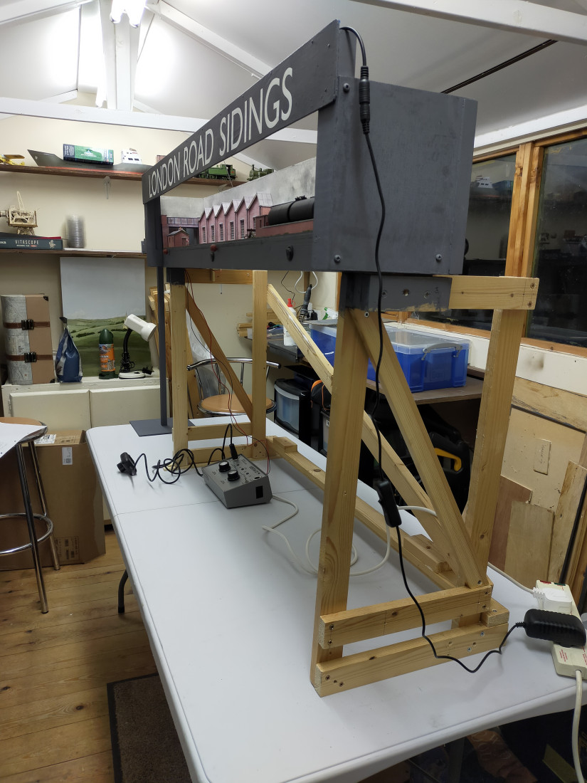
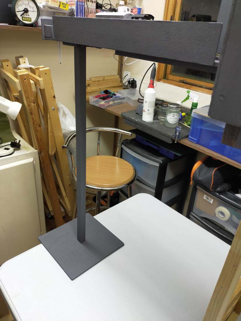
On page 1 of this thread I mentioned that I had constructed two small support frames. These would stand on a typical village hall type table, thereby bringing the layout up to adult viewing height.  I came to realise that the fiddle-stick, protruding from the left-hand end, would require some support so that heavier diesels could be run on the layout. This is how the support arrangement looks.   I have to source a curtain to cover the woodwork.

Terry


IMG20240124194204.jpg
IMG20240124194323.jpg

Last edit: by col.stephens

Online now: No Back to the top

Post

Posted
Rating:
Item has a rating of 5 (Liked by Ed)
#289601
Full Member
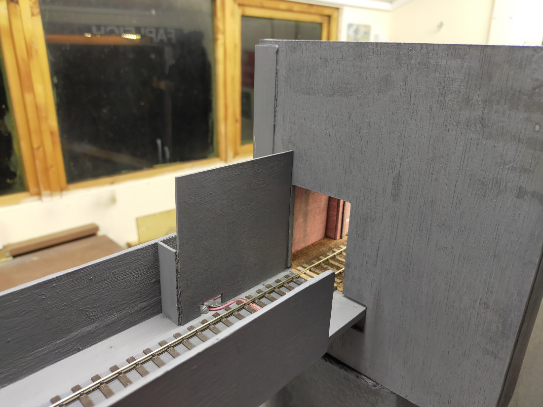
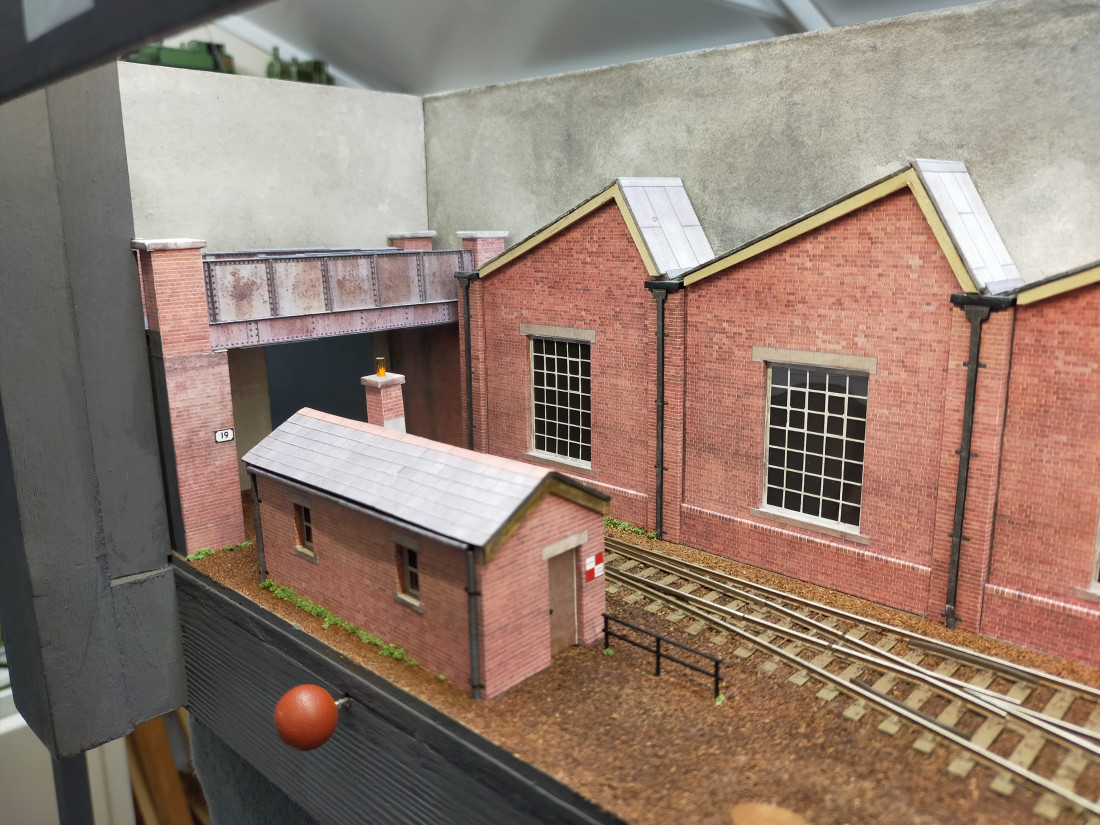
Now that London Road Sidings is booked to appear at a forthcoming exhibition in April, my mind is focused on ensuring that it is presentable to the fee paying public. I decided to block gaps at the ends of the scenic section with card painted the same colour as the surrounding facia. It was also niggling me that it was possible to view the choc-block connectors beyond the bridge on the fiddlestick. These have also been obscured from view, again using painted card. Simple, but makes all the difference to the presentation.

IMG20240203180500.jpg
IMG20240203180436.jpg


Last edit: by col.stephens

Online now: No Back to the top

Post

Posted
Rating:
#289602
Full Member
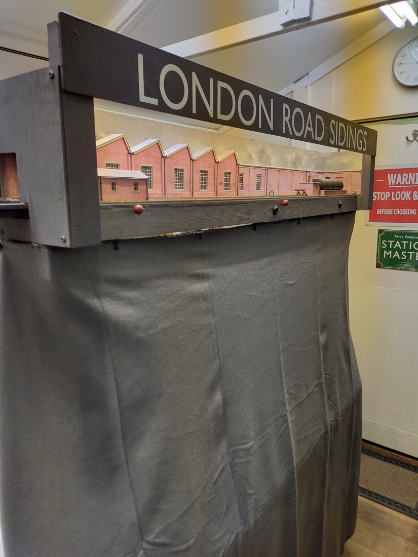
Of course, all that woodwork beneath the layout would need masking if the layout is to be presented in public. A trip to the local B&M chain store resulted in the purchase of a suitable throw (another name for a blanket), for the princely sum of £3! Whilst there I also picked up a small jar of black-headed pins with which to attach said throw. Sorted!

IMG20240203180400.jpg

Last edit: by col.stephens

Online now: No Back to the top

Post

Posted
Rating:
#289603
Full Member
Yard lights have been niggling me for a few weeks. Clearly lights would be provided around the sidings, or how would anyone be able to work after 4pm in the Winter? I was quite pleased with myself for buying some ready made specimens at a recent show. Unfortunately when I offered them up to the layout it was apparent that they were far too large. Although supposed to be for 4mm scale (or 00 as the packet incorrectly stated. Don't get me started on this! You can't have a 00 lamp. 00 is the track gauge. Oh, and whilst we are about it, there is no such thing as 00 scale. You have 4mm scale and 00 Gauge. Manufacturers please note!) the lamps were clearly suitable for 7mm scale. Back to square one!

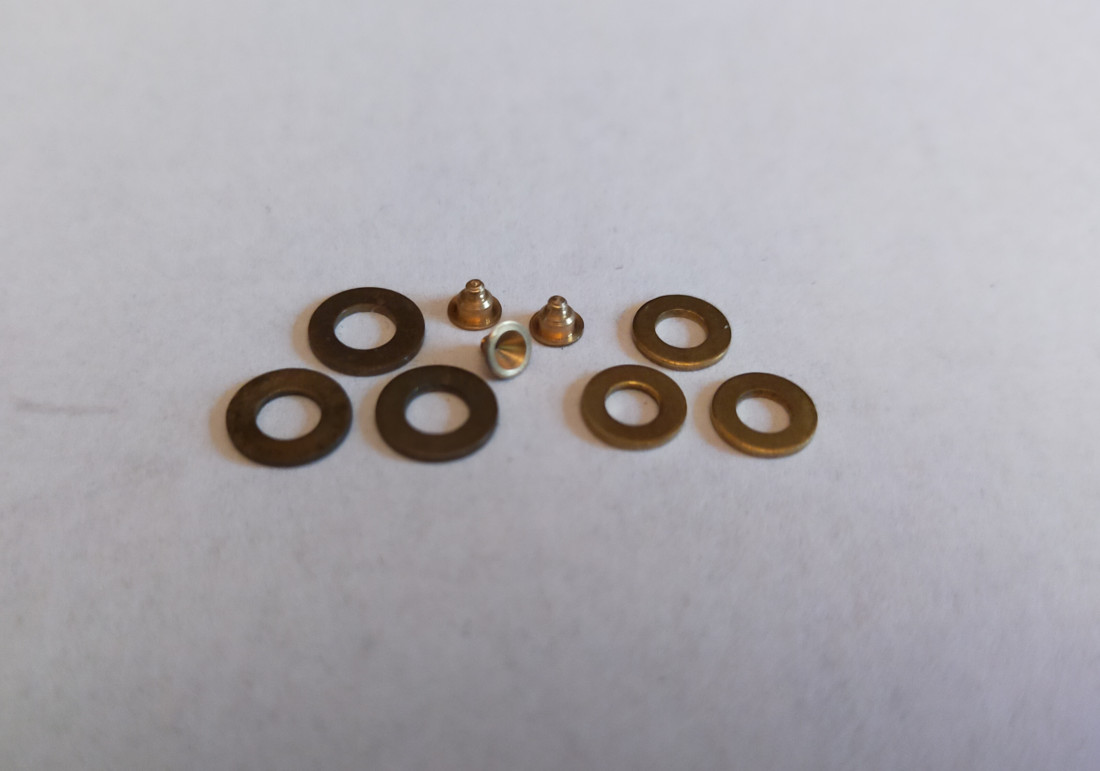
The only answer is to make them yourself. I mulled it over and formed a plan. The following items were produced after a rummage through various boxes..


IMG_20240203_190237.jpg
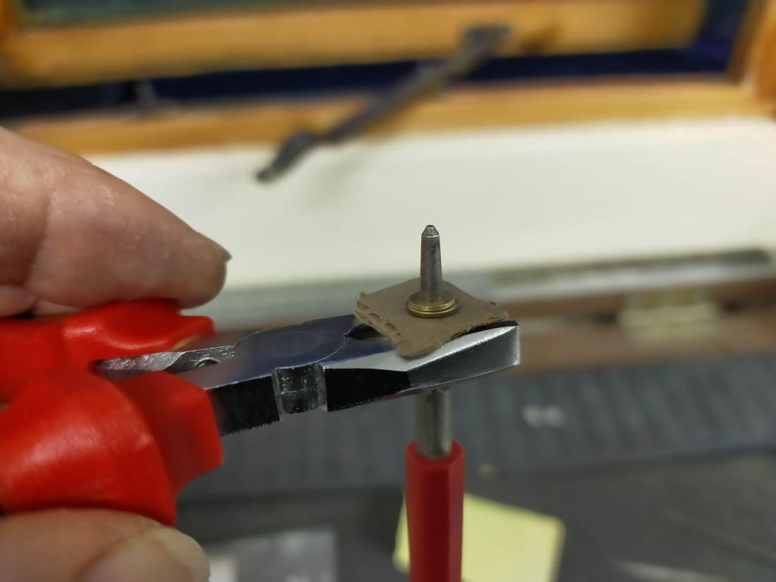
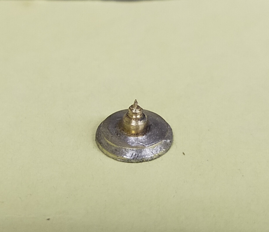
On the left we have brass washers of 7mm outside diameter. On the right we have 3BA brass washers of about 5mm outside diameter. In the centre we have some 4mm scale brass axle bearings. First job is to clean them up and solder a small washer to a large washer. But how to ensure that the centres are aligned? Like this..

IMG20240204170041.jpg
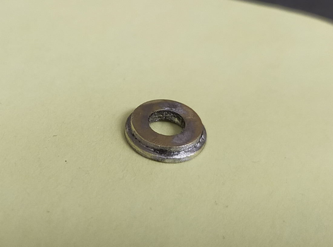
The tool being held vertically is from a soldering kit. What is important is that it is tapered. The card is in place to prevent the heat from the soldering iron disappearing into the pliers. Apply liquid flux and solder to get this..

IMG_20240203_190154.jpg

Last edit: by col.stephens

Online now: No Back to the top

Post

Posted
Rating:
#289604
Full Member
Now solder the axle bearing in place over the hole..


IMG_20240203_190040.jpg
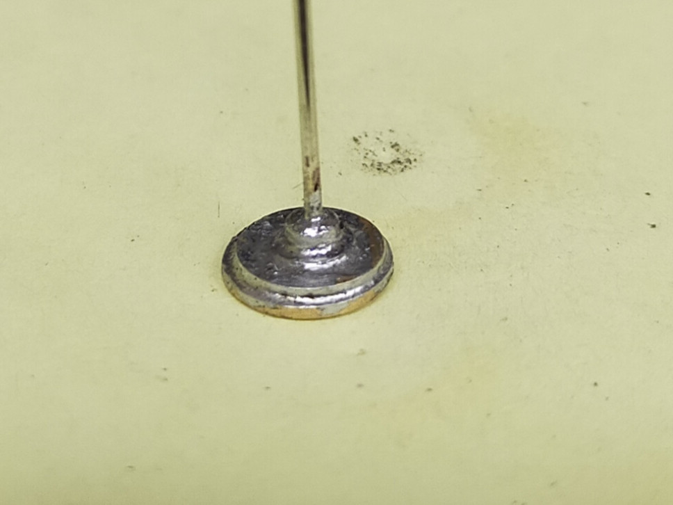
Next, snip of the protruding bit at the top and file flat. Turn over and drill a hole through the centre of the axle bearing. Now solder a suitable length of wire through the hole..

IMG_20240204_184101.jpg
Online now: No Back to the top

Post

Posted
Rating:
#289605
Full Member
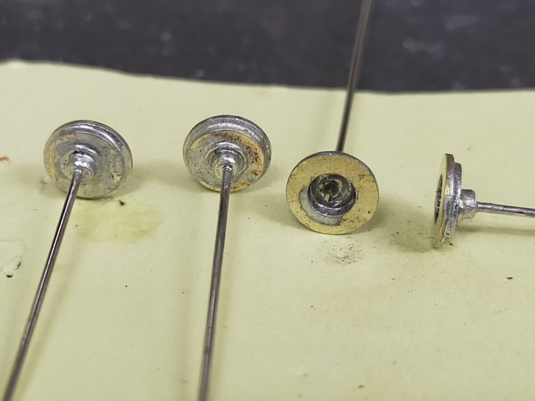
I produced four yesterday which should be enough for the layout..

IMG_20240204_191509.jpg
I'm minded to bend the wire to produce some a 'swan-necked' type lamp standards, or even a typical yard lamp with a loop surrounding the lamp housing. Another lamp will be of the bracket type over a door.
Next I'll solder up two pieces of tube to make each post,

Terry


Online now: No Back to the top

Post

Posted
Rating:
#289607
Ed
Avatar
Site staff
Ed is in the usergroup ‘Super-moderators’
Look good Terry, nice bit of recycling  :staff_silvio5nm:

Ed
Online now: No Back to the top

Post

Posted
Rating:
#289609
Avatar
Full Member
I'm watching carefully.

Neat soldering - is the bearing a normal top-hat type ?

'Petermac
Online now: No Back to the top

Post

Posted
Rating:
#289614
Full Member

Petermac said

I'm watching carefully.

Neat soldering - is the bearing a normal top-hat type ?
Hello Peter.  Yes.  These are Alan Gibson 4mm scale top-hat bearings.   They are from a packet which I have had in store for some time.

Terry
Online now: No Back to the top

Post

Posted
Rating:
#289615
Full Member

Ed said

Look good Terry, nice bit of recycling  :staff_silvio5nm:

Ed
Thanks Ed.  Very kind of you.

Terry
Online now: No Back to the top

Post

Posted
Rating:
#289616
Full Member
More progress has been made with the lamps this evening. I must say that the process of making these lamps is not very time consuming. I estimate that one lamp could be made from scratch, and ready for the paint shop, in about thirty minutes or less, assuming that you weren't rushing the job. On with the work..

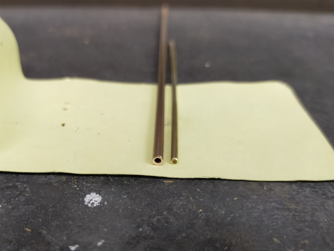
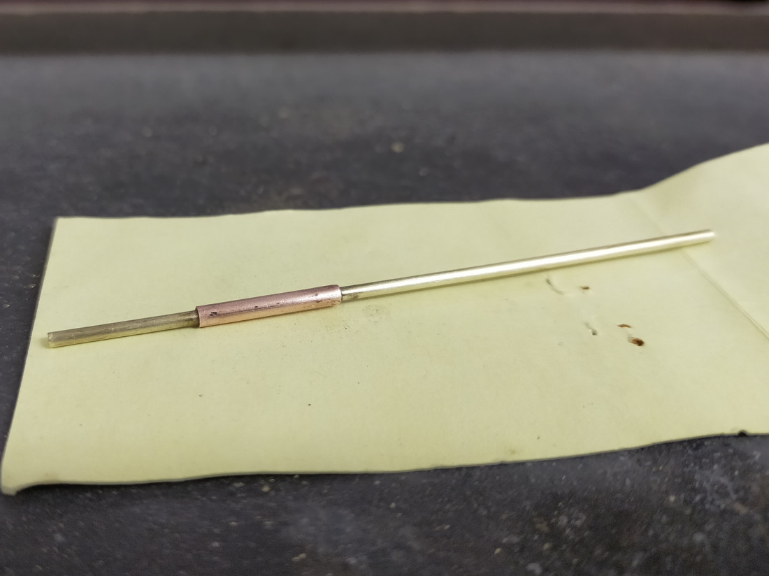
I found a few short offcuts of tube to be used to make the post. One is brass tube of the type used for wire in tube control of turnouts and signals, and the other is a slightly larger diameter copper tube. Any tube will do as long as one will slide neatly inside the other.


IMG_20240205_180709.jpg


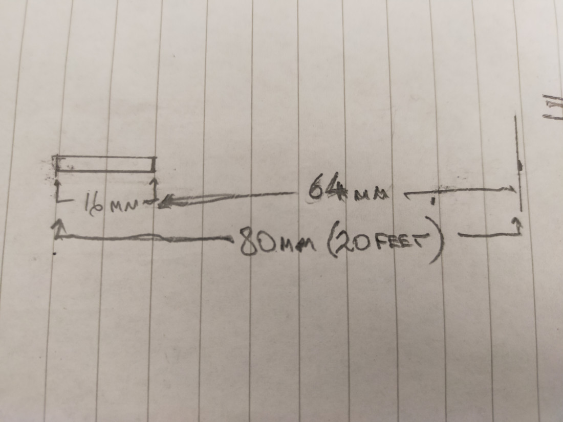
Assuming the lampposts are about 20ft high, a scale drawing would be useful. Obviously, you can adjust the drawing to your preferred height.


IMG20240205182314.jpg


Cut a 16mm length from the larger diameter tube. This will form the lower, and wider, part of the post. Once cleaned up, slide it over the narrower tube and establish its position using the drawing. Also decide on the position of the top of the post, represented by the narrower tube. Solder the tubes together at the top of the wider tube. The narrower tube, protruding from below the wider tube, is to allow the lamppost to be mounted through a hole in the baseboard.


IMG_20240205_181939.jpg
 
Online now: No Back to the top

Post

Posted
Rating:
#289617
Full Member
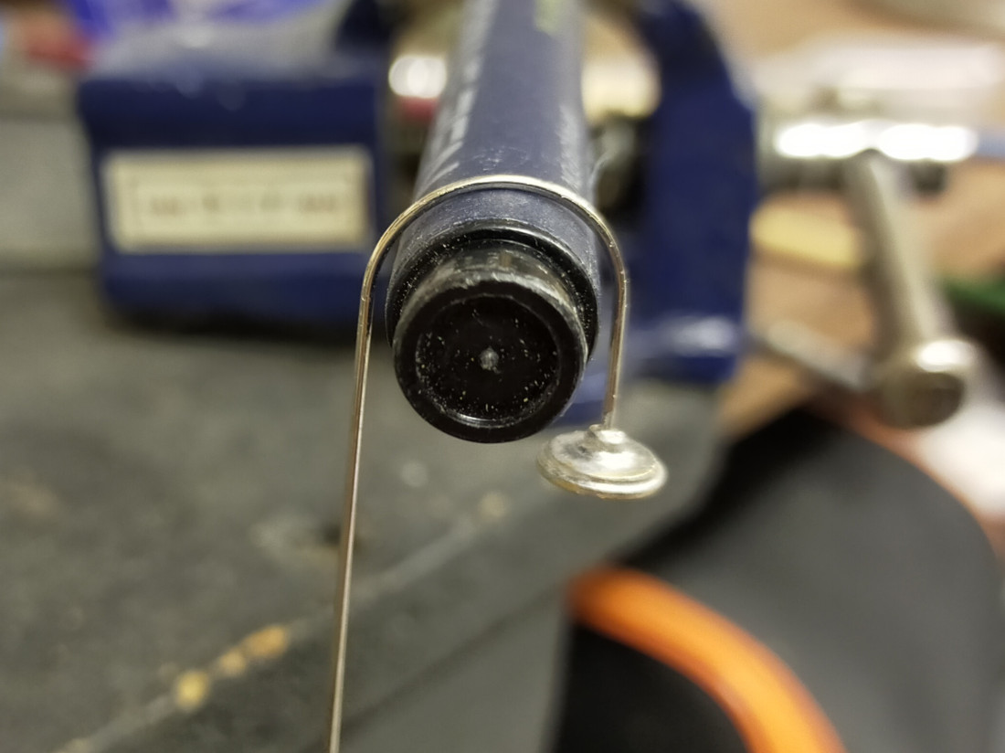
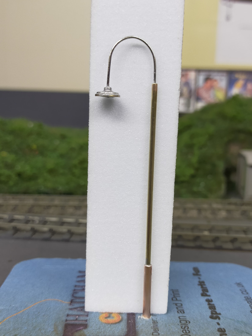
Bend the wire, previously soldered to the lamp tops, around a suitable former. I had used .7mm nickel silver wire and it was a simple job to form a bend around the outside of a drawing pen, using just finger pressure..


IMG_20240205_181042.jpg


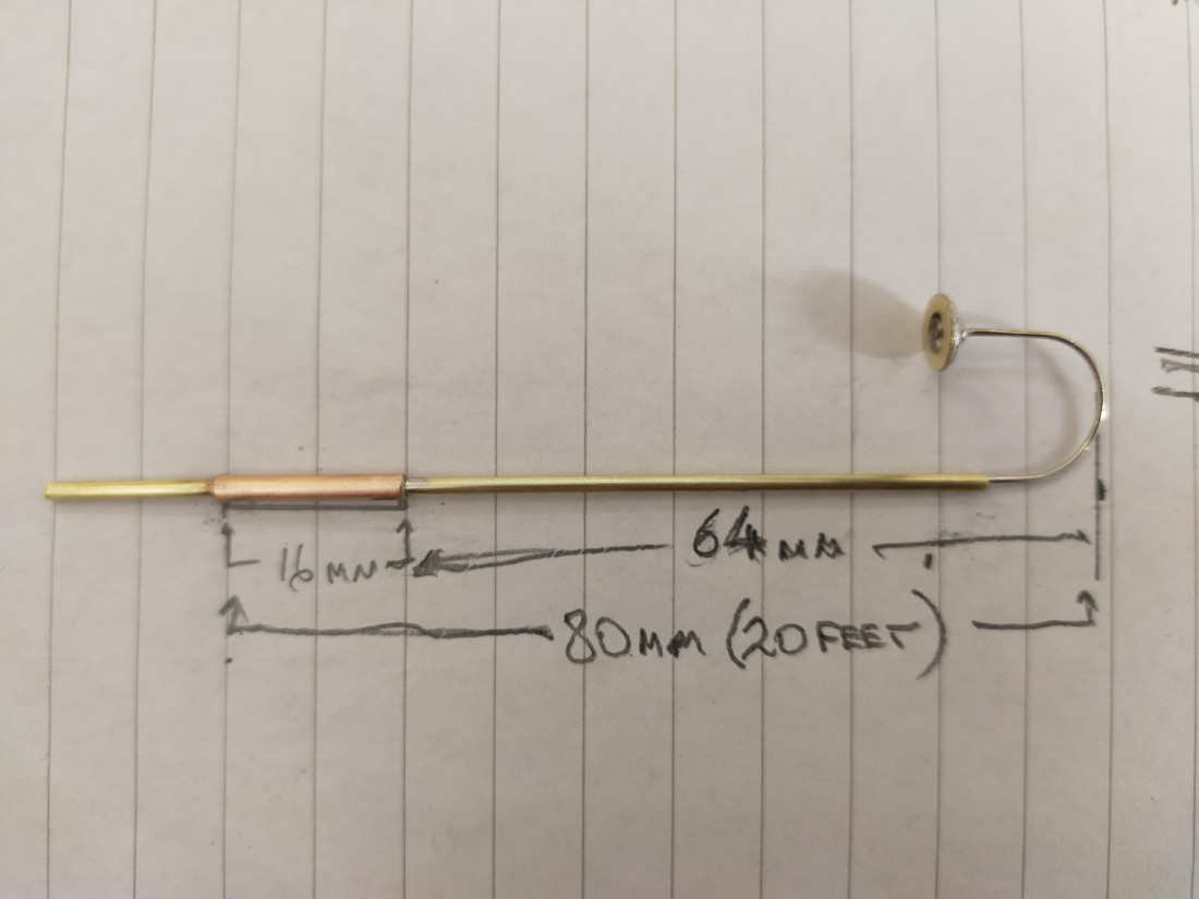
Push the wire into the top of the post. Lay it on the drawing and adjust to the correct height..


IMG20240205182424.jpg


Solder the wire to the top of the post. You should have something akin to this, ready for the paint shop..

IMG_20240205_184258.jpg


Terry

 
Online now: No Back to the top

Post

Posted
Rating:
#289618
Online now: No Back to the top
1 guest and 0 members have just viewed this.