Diesel Refuelling Point

Post

Posted
Rating:
#287247
Full Member

Another quart in a pint pot!

I am now in the process of wiring the layout.  As usual, I like to join each point or length of track to its immediate neighbours with short jumper wires.  The pink wires shown below are connecting the point and adjacent track.  This location is immediately above the support for the fiddle-stick on the underside of the board.  Accordingly, I was unable to just drill holes and run the wires beneath the board as they would foul said support.  The answer was to cut channels in the cork either side of the two rails, and run the wires on top of the baseboard.  The channels and wires will be covered later when the scenery is added.  The red and black wires further up the picture are the electical feed wires.  Again they run away from the rails before disappearing through the baseboard surface to clear the fiddle-stick support beneath.
Click on the thumbnail to enlarge same.
IMG20230410174742.jpg
Terry


Last edit: by col.stephens

Online now: No Back to the top

Post

Posted
Rating:
#287248
Full Member
This picture shows the underneath of the baseboard at the same location as the last picture. I had to route the wires so as not to obstruct the fiddle-stick support.  I opted to hold the wires in place using a hot glue gun.

IMG20230410152857.jpg
Online now: No Back to the top

Post

Posted
Rating:
Item has a rating of 5 (Liked by Ed)
#287405
Full Member
Quick update on this small layout.  The wiring has been completed for DC operation.  Tested and all is well.  I required a couple of rocker switches for the isolated sections on two of the sidings. An internet search showed that it is virtually impossible to find any small surface mounting switches other than those intended for panel mounting.  I wanted to fit the switches on the front of the baseboard frame, the layout being operated from the front.  In the end I decided to order some automotive dashboard rocker switches to experiment with.  Surprisingly, it was fairly easy to attach them to the 2 x 1 inch baseboard frame.  I drilled a 20mm diameter hole completely through the frame and then filed a small area at 12 o'clock and 6 o'clock to clear the two projecting clips which are supposed to secure the switch to the rear of a thin panel.  The switches are a tight fit which appears to be sufficient to keep them in place.  The two wires from the track were then soldered to the projecting tags at the rear.  I must say that the switches look very neat.  The red ball is a bead, glued to the end of the turnout operating wire. (Click on the thumbnail to enlarge).

IMG20230417210831.jpg

Last edit: by col.stephens

Online now: No Back to the top

Post

Posted
Rating:
#287417
Full Member
I omitted to mention earlier that after completing and testing the electrics, I painted the rail sides (and most of the running surface!), chairs and sleepers with Humbrol matt enamel No.186. This is a lovely shade of brown with a hint of red.  My tintlet is an old one manufactured before Hornby trusted the maunufacture to the China, with the ensuing chaos.

Terry

Last edit: by col.stephens

Online now: No Back to the top

Post

Posted
Rating:
Item has a rating of 5 (Liked by Ed)
#287747
Full Member
Since my last post things have been progressing slowly.  The two fuel storage tanks have been sprayed black and have been mounted on a card base together with the pump room previously shown.  I am still working on this and will show a photo when finished.  However, it is sufficiently completed to try it for size in it's allocated position.  Unfortunately, it didn't fit!  When laying the track I slewed the rear two sidings away from the backscene in an effort to created a bit of space between said sidings and backscene (see earlier photo).  The idea was to fit a low-relief building against the backscene.  However, I failed to take into account the fact that I had planned the layout with tracks parallel to the backscene in order that the storage tanks could be fitted at the front of the layout.  The layout is only 5.5 inches wide so everything is very tight.  The only solution was to partly lift the two rear sidings and glue them down again in the correct alignment.  I have inserted a Peco track pin at the end of each siding just to keep everything in place.

Terry


IMG20230513194452.jpg

Last edit: by col.stephens

Online now: No Back to the top

Post

Posted
Rating:
#287958
Full Member
Just a quick update to announce that this project is still very much alive and kicking.  It is just taking me longer than I had anticipated.  However, most of the buildings are complete and are awaiting installation on the layout, just as soon as I have finished the ground work.  I wanted to portray sidings where the track is typically buried to the top of the sleepers.  I have never seen this achieved realistically on any model railway that I have personally viewed.  I'm not saying that it hasn't been done, just that I have never witnessed it.  I decided to experiment with some ground cover which I'll comment on further if it is a success.  It is taking me a while but things are slowly progressing.  Watch this space!

Terry
Online now: No Back to the top

Post

Posted
Rating:
#287964
Online now: No Back to the top

Post

Posted
Rating:
#287970
Full Member
Thanks Ed.

Today I have done a bit more work on the ground cover and although it is not finished, now that I have taken some pohotos, I feel that I can share it with you.  The thing which mainly stands out to me when viewing the track in yards and sidings, is that the track is normally buried to the tops of the sleepers.  The chairs and rail usually stand clear above and do not have ash or earth clinging to them.  I have seen attempts to model this where ready-mixed plaster has been dragged along the track and looks unrealistic because a good portion of it is piled up on the rail sides and chairs.  What to use?  I considered fine ballast, but it looks like ballast and is not usually spread over the whole yard on the prototype.  I looked around for something reasonably fine and preferably free.  Enter the humble used tea bag!  Yes those soggy brown things which you throw straight into the bin, or compost in my case, at least ten times a day (applies to UK only.  Adjust total to suit your location, probably downwards I imagine).

I began by saving all of my used tea bags and laid them out in the sun to dry.  Recently , the UK weather has been ideal for this.  I then invested 99p in a tea strainer.  Every UK home had one of these at one time when loose tea was put in a pot to brew.  Of course, the use of tea bags has done away with them, plus tea pots and tea cosys If you don't know what I'm talking about, ask your mum or dad.

I first experimented with tea bags some five decades ago to represent ballast on a small OO Gauge model.  I used the tea straight from the dried tea bags and the result?  Although a nice brown colour, It looked like the track had been ballasted with tea leaves!  So, enter the aforementioned tea strainer.  The contents of each tea bag was put through the strainer twice to remove the larger leaves.  The resultant finer leaves and dust is what is going onto the track.

Firstly, I decided to fill between the rails and on either side to the ends of the sleepers.  I simply poured the tea onto the track and treated it much like the usual ballasts which we use.  Once tidied up and removed from the sleeper tops, I sprayed the complete area with plain water.
I had already mixed an amount of PVA with water in a jam jar.  I'm not precise about this.  I just pour a big blob of PVA into the jar and add sufficient water to make it runny when stirred.  This mixture was then applied to the track with a small pipette.

Once the diluted PVA has soaked in (just a few seconds), the tea becomes almost like a mash and can be smoothed and pushed into position with a suitable tool. I use a palette knife bought as part of an artist's set from a cheap stationary chain.

IMG20230620160921.jpg


The picture above shows the wet tea being smoothed.  As I am using Peco Code 75 turnouts, which have thicker sleepers than the C&L track, the tea has been built-up to the sleeper tops.  The turnout and track had been previously treated with the tea and were dry.  In this photo I am adding the ground cover from the sleeper ends to the picture foreground.

Terry

 
Online now: No Back to the top

Post

Posted
Rating:
#287974
Full Member
In other areas beside the plain C&L track I simply painted neat PVA onto the baseboard surface and sprinkled the tea thereon, leaving it overnight to dry.  One dry, the tea was vacuumed off.  I noticed that when applying the tea by this method it remains a light brown colour, as opposed to the darker colour which results when the tea has been soaked with the water spray and then had diluted PVA applied.  My conclusion is that, although the tea applied directly to the neat PVA is firmly fixed, the diluted PVA treatment has to be undertaken to give all of the tea a similar appearance.  Note the differing colours in this photo between the centre of the track and the area in the foreground.

IMG20230620162045.jpg

Terry
 

Last edit: by col.stephens

Online now: No Back to the top

Post

Posted
Rating:
#287975
Full Member
Currently the areas between the tracks are being covered.

IMG20230620163309.jpg
Online now: No Back to the top

Post

Posted
Rating:
#287976
Full Member
When the tea has dried, I tidy up by running a foam sanding block over the track surface to remove any tea leaves stuck to the sleeper tops and chairs.  I'll post some further photos in due course.  Please bear in mind that the photos are in cruel close-up and the finished effect, when viewed from the normal viewing distance, appears to be much finer.

Terry
Online now: No Back to the top

Post

Posted
Rating:
Item has a rating of 5 (Liked by Ed)
#288072
Full Member
The layout is slowly progressing.  I want a change from the eternal summer with blue skies, much beloved of railway modellers.  I am leaning towards painting an overcast sky, with the sound of a distant storm brewing (courtesy of a mini-speaker purchased a few years ago).  I want to create the impression that we have already had a drop of rain and decided that a few puddles on the ground would be just the job.  I am using microscope slide covers measuring 18mm x 18mm.  First, I laid the slide covers on the ground surface and drew around them with a pencil.  I removed the tea leaves and cork to a depth with seemed suitable.  One side of each slide cover was painted with an appropriate shade of enamel paint.  When dry, each was laid in its hole on a bed of pva., painted side downwards.  Ready-mixed plaster was built up around the edges of each slide cover and left to dry. (Sorry about the huge photos.  I have tried to reduce the size to no avail).

IMG20230630150604.jpg

Last edit: by col.stephens

Online now: No Back to the top

Post

Posted
Rating:
#288073
Full Member
IMG20230630151536.jpg
Online now: No Back to the top

Post

Posted
Rating:
#288074
Full Member
IMG20230630150612.jpg
Online now: No Back to the top

Post

Posted
Rating:
#288100
Full Member
Peco buffer stops have been superglued in place at the end of the three sidings.

IMG20230630160418.jpg

Last edit: by col.stephens

Online now: No Back to the top

Post

Posted
Rating:
#288101
Full Member
IMG20230630152812.jpg
Online now: No Back to the top

Post

Posted
Rating:
#288159
Full Member
Tea leaves added to the puddles.
IMG20230709175510.jpg
IMG20230709175355.jpg
Unfortunately, the single puddle appears to have developed some marks on the underside of the glass.  I may mask these with tea leaves.

Terry
Online now: No Back to the top

Post

Posted
Rating:
Item has a rating of 5 (Liked by Ed)
#288160
Full Member
The ground cover has been completed.  Time now to add the buildings or possibly the layout lighting.

IMG20230709175553.jpg

Last edit: by col.stephens

Online now: No Back to the top

Post

Posted
Rating:
#288251
Full Member
Work on the layout is progressing.  I decided to install the lighting next.  The word 'install' is a bit misleading as basically, I cut a short length of LED strip from the spool on which it comes, peeled of the paper backing to reveal the sticky back, and simply pressed it into place.  Total time taken in this task about two minutes!  Great stuff this LED strip.  I really would not revert to neon lamps, spotlights, or any of that pre-history nonsense.  I buy the LED strip online on the usual auction site.  It comes pre-wired to an on/off switch and 12v transformer plug.  I checked yesterday and 5 metres can be obtained for just over £12 Sterling.  Great value.
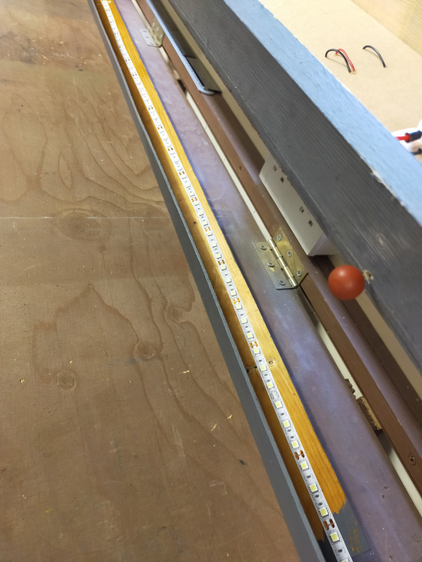
Here is the upturned layout showing the LED strip in place.

25 views (3 MB)
Terry


Online now: No Back to the top

Post

Posted
Rating:
#288252
Full Member
I decided that it was time to complete the backscene before adding the structures to the baseboard.  The backscene board is basically a strip of plywood with two plywood end pieces.  In order to get a suitable surface on which to paint, I covered the plywood with lining paper, bought from the wallpaper section of a  chain store.  The lining paper was fixed to the plywood with wallpaper paste and then a small roller was run over the surface to squeeze out any excess paste.  When dry, the result was a perfectly flat surface with no air bubbles beneath.  For this particular layout I wanted to get away from the usual clear blue summer sky, much beloved by railway modellers.  My aim was to produce a grey, sullen sky with dark threatening storm clouds approaching.  I intend to have the sound of a distant thunder storm when the layout is being operated (more on this eventually).

Out came the large, cheap tubes of acrylic paint, purchased from the usual chain stores for about £2 each.  I used just three colours: white, black, and a minute amount of yellow ochre.  Plain water was liberally painted onto the surface.  White was mixed with a small drop of black to give a light grey, which was quickly painted on and dabbed in places with a piece of kitchen roll to create a cloud effect.  Hard edges were softened by brushing on plain water.  Whilst wet, small amounts of diluted black were added to the surface to give the impression of dark storm clouds, with a minute dab of yellow ochre added in places and brushed over with water to disperse it.  Experimentation is very much the order of the day, leaning towards less rather than more.  One important thing to remember.  As you work your way along the surface to be painted, do not allow the edges of the painted area to dry as you will get a hard edge in your sky.  For instance, I was working from left to right along the 4ft backscene, painting about sixteen inches at a time.  As I was working, I kept an eye on the right side of the painted area, and kept painting water over the paint edges to prevent them from drying until I was ready to move onto that area.

Sadly, when the buildings are in place much of the sky won't be seen.  However, this is merely a backdrop to create the atmosphere.  Just as in the theatre, the action will be taking place downstage (towards the audience).

Right-hand end of the backscene.


IMG20230717202347.jpg
Terry


Online now: No Back to the top
1 guest and 0 members have just viewed this.