Diesel Refuelling Point
Posted
#266093
(In Topic #14491)
Full Member
Another quart in a pint pot!
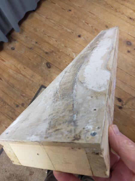
Can it really be nine years ago that I anounced to the world that I was going to build a 'layout' on a piece of mdf measuring four feet by five and a half inches?The finished item represented a UK roadside tramway and along the way picked up the name 'Poppy Lane'. It subsequently appeared in the October 2017 Railway Modeller. The combined length of the three pages in which it appeared almost totalled the actual length of the model itself! The layout can be found here:
A 'watching the trains go by' plank. - Members Personal Layouts. - Model Railway Layouts. - Your Model Railway Club
So, what has all this got to do with the current thread? After it's fifteen minutes of fame Poppy lane has been sat on a shelf in my railway shed gathering dust. Last week I decided that it was time to dismantle it. The track and scenic items were retrieved for future use and I was intending to separate the baseboard top from the frame and re-use the timber. However, a chance remark by my wife about using the intact baseboard for another project made me think again. Can I build another micro-layout on the recycled baseboard?
This is my starting point (once again)…
Terry
 Last edit: by col.stephens

Posted

Full Member
Bon courage mon ami.
At 6'4'', Bill is a tall chap, then again, when horizontal he is rather long and people often used to trip over him! . . . and so a nickname was born :)
Posted
Full Member
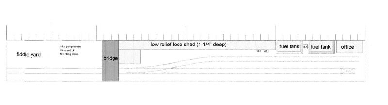
Basically two sidings with a single road fiddle yard. This will allow me to run a succession of different diesels to be refuelled and depart again. Another train movement would be a loco and two tank wagons arriving to refill the static fuel tanks. I can't really think of any other train movements but will be interested to hear if anyone has any ideas.
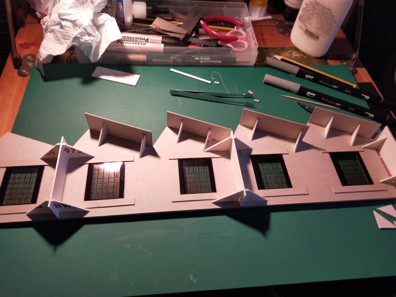
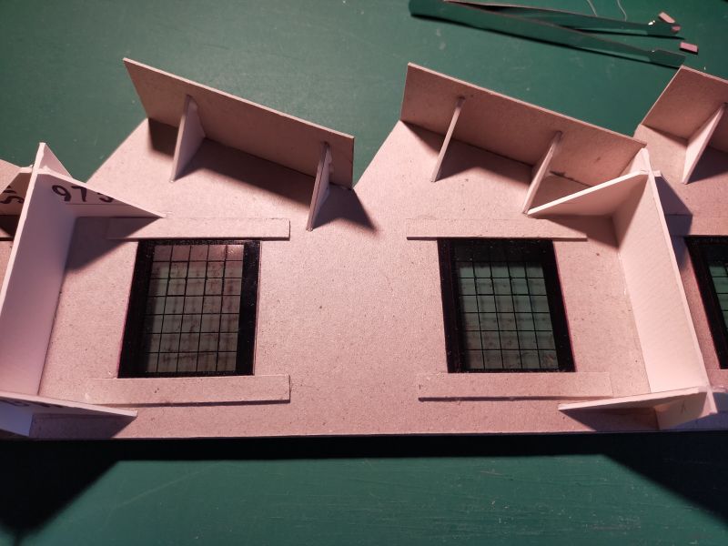
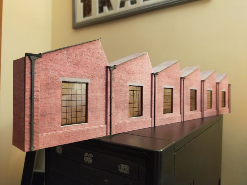
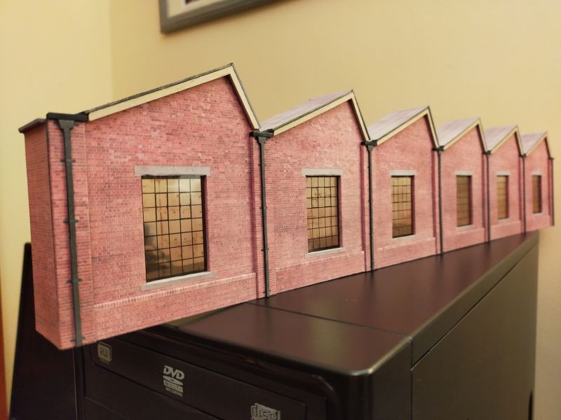
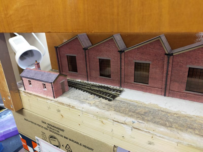
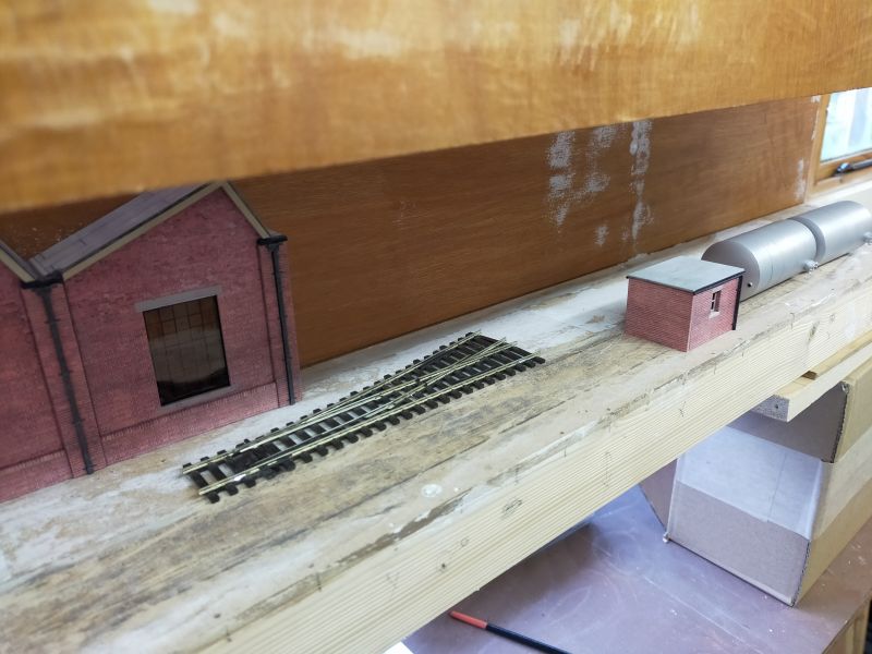
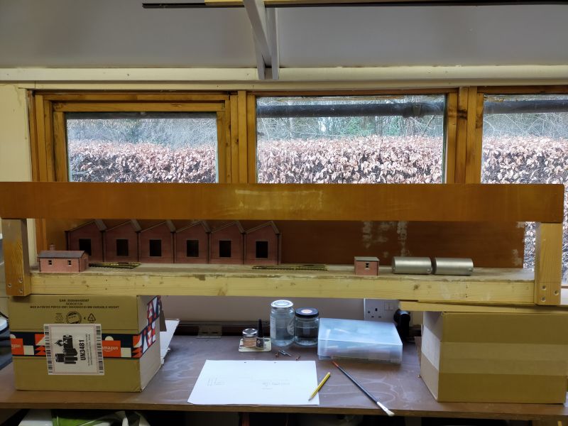
I thought that I would begin by building the low-relief building which runs for over half of the length of the scenic section. On the plan I have called it a loco shed but it could be a works of some sort. The building is there purely to present a background to the sidings and it's actual purpose is of no real consequence. I thought it would be interesting to have a varied roof line so I opted to use Scalescenes' North Light Engine Shed as the basis for the model. The actual Scalescenes' model is in full relief but I have only used one of the outside walls which is glued to 2mm greyboard No interior walls or other details were used, but I have used some bracing where appropriate. I am currently fixing the roof in place.
Any suggestions or ideas re this small layout welcome.
Terry
Last edit: by col.stephens
Posted
Full Member
Terry
Last edit: by Barchester
Posted
Full Member
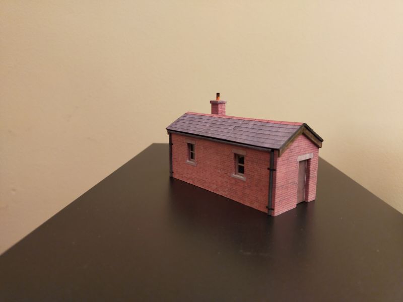
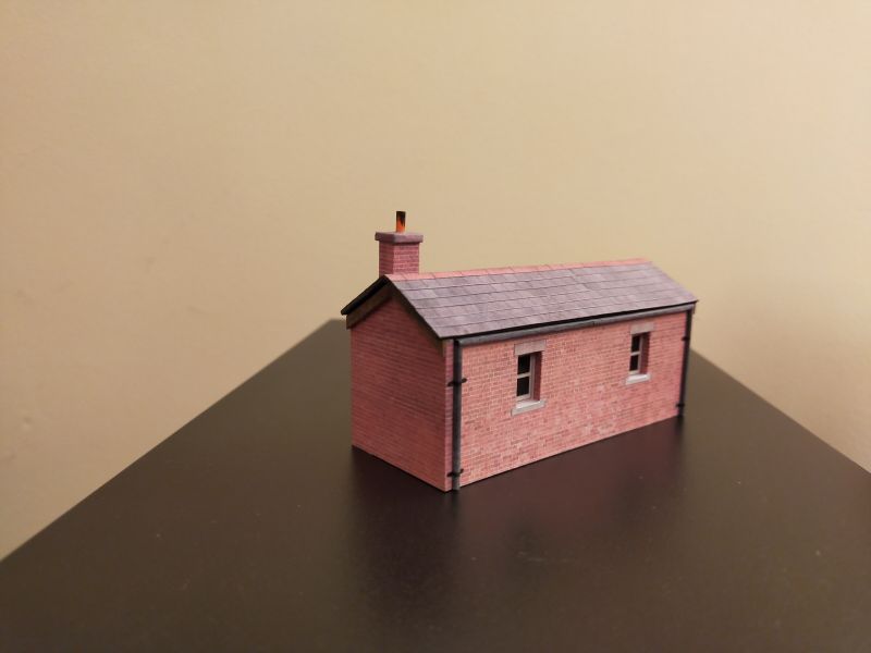
I have printed off the other Scalescenes' buildings required, these being the plate girder bridge and the coal office/weighbridge office which will be used as a bothy. The only other building at the far right of the plan above will now be pushed into use as the pump house and will be constructed from parts from the coal ofice/weighbridge kit. Basically it will just be an elongated version of the original model.
I have decided to construct all of the buildings to try them for size before laying any track.
More soon.
Terry
Last edit: by col.stephens
Posted

Full Member
I do like the flexibility of scalescenes.
Posted
Full Member
Posted
Full Member
* Possible inclusion of the micro-layout in a forthcoming exhibition.
Here's the result…
More soon.
Terry
Last edit: by col.stephens
Posted
Full Member
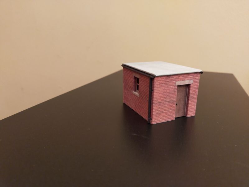
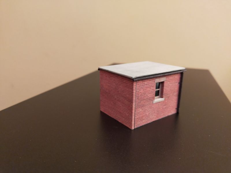
A quick and simple build.
Terry
Last edit: by col.stephens
Posted
Full Member
Jeff Lynn,
Amateur layabout, Professional Lurker, Thread hijacker extraordinaire
Amateur layabout, Professional Lurker, Thread hijacker extraordinaire
Posted
Full Member
Terry
Posted
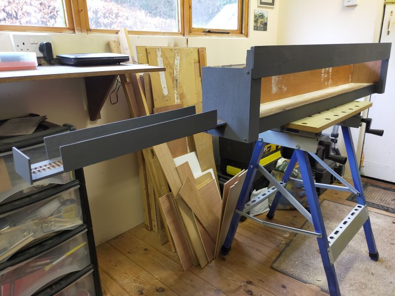
Full Member
Over the last couple of weeks attention has been given to how the layout will be supported. I have made two small support frames on which each end of the layout sits. Two cross-braces keep them upright. In turn, these frames will stand on a typical village hall type six-foot table bringing the baseboard top up to a comfortable adult viewing height.
A lighting pelmet has been fashioned using part of that which was attached to Poppy Lane. It stands proud of the front of the baseboard but I think that it needs to extend further from the front of the layout in order to throw light on the front edge. I will give this attention shortly. The original Poppy Lane backscene board has been re-used and is awaiting a coat of sky coloured paint. All woodwork will be given a coat of slate grey emulsion when completed.
The original track plan was giving me some concern in that all structures were placed against the backscene. I felt that more interest would be created if some structures were at the front of the baseboard. Accordingly, I have re-worked the track plan to give three sidings instead of the original two. This will allow the fuel tanks, pump house and bothy to be situated at the front, with trains passing behind. I haven't drawn another track plan but the following photos should give an idea of the new plan.
This is the left-hand end beyond which the fiddle-stick will be situated. A Scalescenes' girder bridge is under construction to fit at this end. Placing the bothy as shown will help mask the fiddle-stick and creates more interest as trains pass behind. The right-hand point creates a short siding at the front ot the layout, which ends just before the pump house and fuel tanks. The straight road leads to the second point and then straight on for the 'fuelling road', so locos actually stand behind the fuel tanks, which I think will create a more interesting view than the original plan.
This is the right-hand end with the second point, it being left-handed. The short siding from the first right-hand point will end just befor the pump house. A Peco buffer-stop will look good here. The straight road will be used for re-feulling locos with a short siding to the left against the backscene.
I haven't quite worked out all of the details yet. For instance, there is an empty space of about six inches long to the right of the fuel tanks. As I only arrived at this reworked plan this afternoon, I haven't had time to give any thought to this area as yet. No doubt something will occur to me in due course. Onwards and upwards!
Terry
P.S. The layout will not be appearing at my club's exhibition in May, so no pressure to rush it now. I will be demonstrating making buildings from card instead.
Posted
Full Member
Posted
Full Member
 The layout will actually be slightly higher when on its legs.
Terry
Last edit: by col.stephens
Posted
Full Member
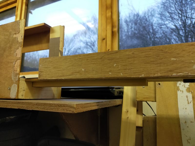
The idea is to support the fiddle-stick on a strip of wood, which passes through a hole in the baseboard end. I carefully drew the shape then drilled a number of holes, followed by cutting away material with a small saw. Files were used to take the wood back to my previously drawn pencil lines. The strip wood is a firm fit in the hole.
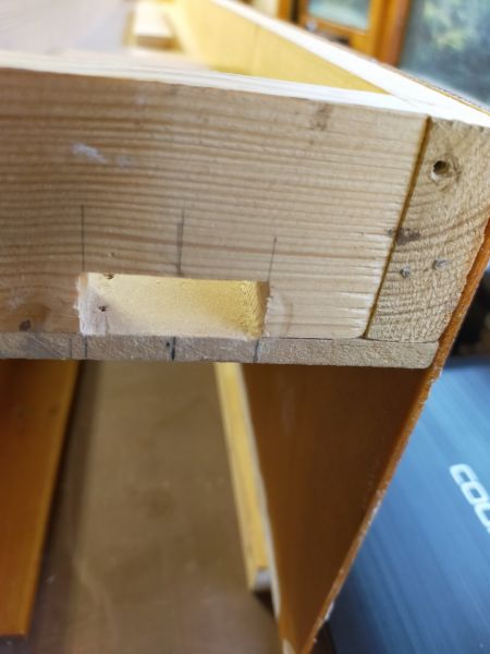
I then constructed a small arch from three pieces of wood to accept the end of the strip of wood. Again, the strip of wood fits tightly in the hole created.
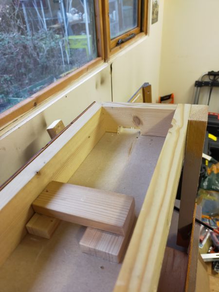
In this picture the strip of wood has been pushed in to assess the fit.
The baseboard has been turned over and the fiddle-stick is placed on the strip of wood to establish the best position in relation to the main baseboard.
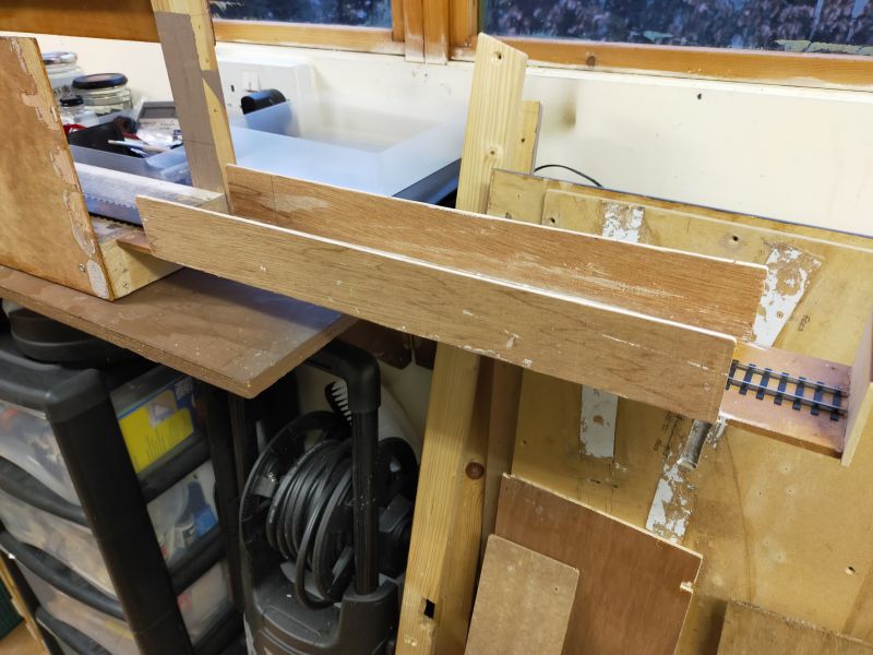
After taking the last photo, I removed the fiddle-stick and the strip of wood was given a liberal coating of 'Resin W' wood glue. The fiddle-stick was replaced and after some final adjustment, a number of small lengths of 2x1 wood were placed thereon to ensure the fiddle-stick is in good contact with the strip of wood. Hopefully, tomorrow I should be able to pull the fiddle-stick away as a one-piece unit.
Terry
Last edit: by col.stephens
Posted
Full Member
I have had quite an enjoyable time constructing the plate girder bridge from the Scalescenes' kit.
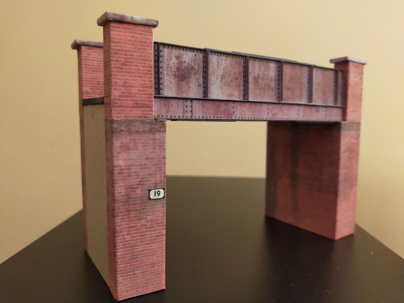
The bridge looks long but is in fact only 5.5 inches in length, that being the width of the baseboard. I think that I will tone down the brickwork on the buttresses.
Terry
Last edit: by col.stephens
Posted
Full Member
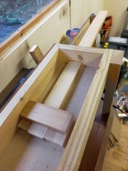
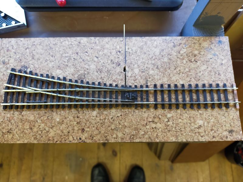
The whole of the baseboard surface was covered with cork floor tiles which I have had in store for some time. I intend to include a puddle or two on the baseboard surface, and my thinking was that it would be easier to dig away at the cork rather than the plywood baseboard. However, using the cork tiles has proved to be rather fortuitous as one of the two turnouts sits directly above the wooden support to which the fiddle-stick is attached. Said support effectively prevents any means of operating the turnout from below the baseboard. This was overcome by cutting a narrow channel in the cork and running the turnout operating rod along the top of the baseboard with a ninety degree bend taking the rod up through the hole in the centre of the stretcher bar. Both turnouts will be operated from the front of the baseboard via push-pull rods, using large beads as the control knobs.
Below you can see the rod running in the cork channel as it comes away from the turnout. It disappears through the hole and re-emerges from the baseboard front. The rod and the hole will be buried, hiding them from view.
Terry
Last edit: by col.stephens
Posted
Full Member
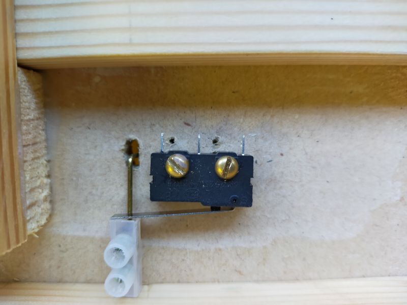
Switch open…
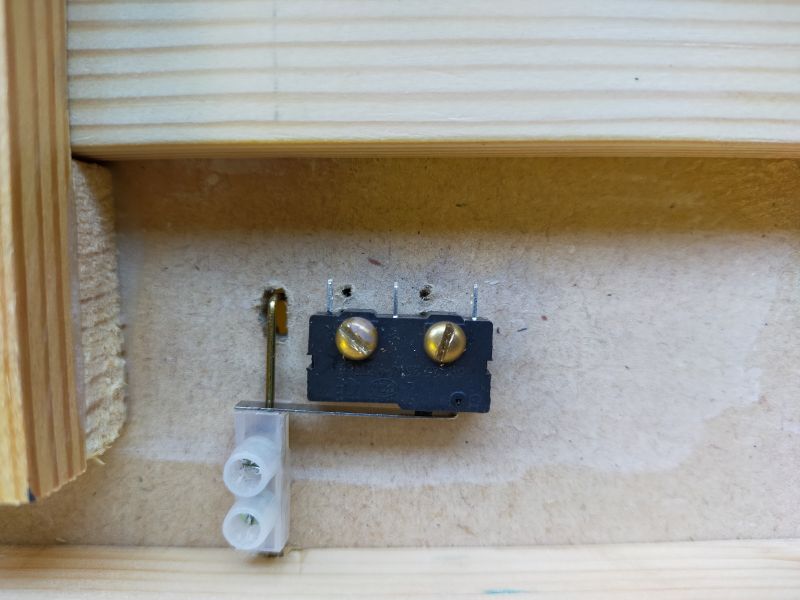
Switch closed…
Currently the track is being laid in position. The two turnouts will be pinned and the remainder of the track will be glued in place.
More soon.
Terry
Last edit: by col.stephens
Posted
Full Member

Last edit: by col.stephens
Posted
Full Member


Last edit: by col.stephens
1 guest and 0 members have just viewed this.