Relaying track
Posted
Full Member
Biting the bullet.
I don't know what happened with my post, but I tried to attach a PNG screenshot and ended up with a load of gobbledegook, I'll give it another try.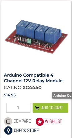
That's better.
Cheers Pete.

Posted
Full Member
Sorry to hear it didn’t work.I suggest you disconnect the diode matrix and test out each point motor by just supplying each with the required signal polarity to the connections.
i.e.
Say all number 8 connections as common ( bipolar) together, then connections number 1 in turn with + ve and then - ve. to check that the point movements are correct.
As I understand it the signals are 0v - common and +ve, -ve to change motor direction.
I see you have found a relay board rated at 12v, there others which I believe only need 3-5 v , switch electronics in UK supply along with others, not used them personally but from what I have read they can be used and triggered without aldrino
Regards
Barry
Further thoughts.
With all point motors disconnected check out signal from matrix with multimeter for each rotary switch position to make sure all diode connections give +ve ( rotary switch Gang1) then all gang 2 connections only give -ve.
If all is well set all points to sidings position with external supply and with only gang 1 connected to supply and set to position 1 with all motors connected and power on they should all go to set track to straight running.
Working through one motor and position at a time firstly in one direction using gang 1 only connected +ve to supply then by connecting supply to gang 2 -ve in the other direction it might reveal the problem.
 Last edit: by Barry Taylor
Posted
Full Member
In that the track layout is relatively simple I would just use DPDT toggle switches to operate them and use the auxiliary switch connections to show route selection lights or the switches themselves. This is how I have done mine.
The straight through route 1 indicator being dependant on all switches in say down position relaying power through each switch to the panel light so that if any one of them is in the up position operating a motor for any siding the panel light goes out.
Similarly the other siding indicator lights can be wired reliant on the previous point.
Regards
Barry
1 guest and 0 members have just viewed this.