Relaying track
Posted
Full Member
Biting the bullet.
Thanks Peter,I'll be busy tomorrow… new oven, bench top and splashed out on an induction cook top, so I'll start the real fun part of wiring up the point motors, testing the track for shorts and other faults and filling in the sleeper gaps as and when I'm released from these other duties. I'm not up to much in the drawing department, but I'll try and do a track plan how it's turned out as opposed to how it would have been if I'd had the length.
As for the car: it lives under a carport but there's still room to get it in the garage if there's a serious hail storm.
Cheers Pete.

Posted

Full Member
Induction stove. Hope you took out a 5 year extended warranty. We have one, just replaced with a new one after 4 years light use. Out of action for 6 months during which time all circuit boards were replaced and it still didn't work. Finally declared a lemon.
Nigel
©Nigel C. Phillips
Posted
Full Member
Cheers Pete.
Posted
Full Member
Posted
Full Member
I've had a day or two away from it, but will be starting on the wiring soon… real fun. I'm actually looking forward to starting some scenery with this one.
Cheers Pete.
Posted
Full Member
The car all ready does live outside under a purpose built car port extension. I only use half the garage width: about 9' so we can get it in when we have proper Aussie hail storms.
I'm still plugging away at wiring and making so many mistakes it ain't funny… getting very frustrated with getting old and forgetful/easily confused. I've done all this before but just keep making mistake after mistake. Ah well.
I will get back to you… eventually. :)
Cheers Pete.
Posted
Full Member
I'm still going at it. I've got the track down and all the Tortoise motors fitted and am now having fun wiring up two double slips with rotary switches, oh what fun. I'm using rotary switches where you buy the mechanisms and wafers separately which means that I use two wafers per switch; one for the point motors and the other one for leds.
I've tried contacting SE Finecast about their 9" turntable kit but no reply via email. I might ring them tonight, our time and see what they have to say. I do have the Peco 12" but that can only go in at the wrong end of the layout. I might even have to do that, after all it's not a scale model, just an approximation of Wadebridge.
Cheers Pete.
Posted
Full Member
I'm taking two steps forward and one back with the wiring of the rotary switches. I'll get there in the end, but it'll take a bit longer than I'd hoped.
Cheers Pete.
Posted
Full Member
Cheers Pete.
Posted
Full Member
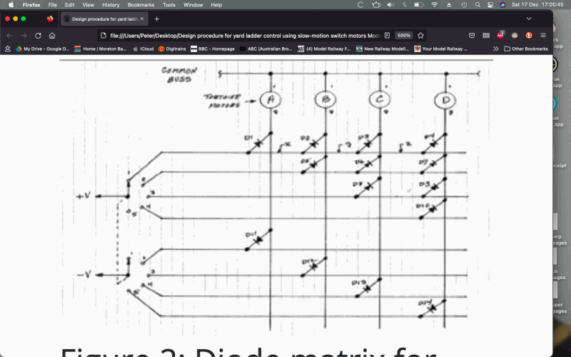
I'm as sure as I can be that I've made the matrix right. I'm attaching a plan for a 5 track/4 motor (tortoise) matrix. I'd appreciate it if someone could tell me if they think it's right. I'm using rotary switches as in the sheet I found on an old American modelling mag'.
I've made sure the diodes are the correct way round and I've only made connections where there are the black dots. I've wired the switches so that the negative (lower) side starts at fig 2 as in the drawing.
This is really annoying as I've done all this before and now I can't make it work. Age or what? Anyway, as I said, if someone can check that the plan is right, I'll at least know to start looking somewhere else.
Cheers Pete.
Posted
Full Member
I’ve tried to work it out but it’s baffled me, sorry!
Posted
Full Member
Cheers Pete.
Posted
Full Member
Cheers Pete.
Posted

Site staff
Ron
NCE DCC ; 00 scale UK outline.
NCE DCC ; 00 scale UK outline.
Posted
Full Member
As you'll see, my sidings are laid out differently to those I first uploaded.

 Last edit: by peterm
Cheers Pete.
Posted
Full Member

Cheers Pete.
Posted
Full Member
 Hi Peter,Just caught up with your latest on diode matrix.
If you google search DIODE MATRIX-BRIAN LAMBERT and scroll down to the relevant section as he has a lot of information relating to most model railway electrics.
Hope this helps.
Regards
Barry T
PS
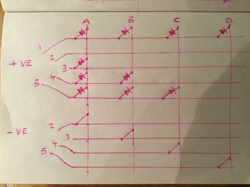
After a few hours head scratching whilst on Christmas holiday visit to IOM and using wife’s pink pen and nail file as ruler, I think a couple of tweaks to your diagram of Sat. 17th December might do it ?I would be pleased to know what you think even if I have got it completely wrong and my logic is up the creek but fingers crossed it will work for you.
Last edit: by Barry Taylor
Posted
Full Member
Best wishes for Christmas and new year.
Pete.
Cheers Pete.
Posted
Full Member
Then as each relay is operated in turn the polarity of any motor can be changed to select a siding.
This may have the advantage of using the relay contacts to illuminate panel indicator lights if placed near control panel and not use tortoise motor contacts.
Another way would be to just use DPDT toggle switches to change polarity and use auxiliary contacts of the switches to illuminate panel lights, again saving wiring depending on where sidings are in relation to control panel.
Both of these alternatives mean you don’t need a diode matrix.
All for now, have a good Christmas and NewYear.
Regards
Barry T
Posted
Full Member
I've made the diode matrix as per the drawing, but it only changes the points so that they're either all normal or all reversed, ie, tracks 2,3 and 4 do nothing when I select them.
Please see next post.
Last edit: by peterm
Cheers Pete.
1 guest and 0 members have just viewed this.