Upper Hembury GWR Branch Line
Posted

Full Member
Updated plans and now moving ahead
Thanks Peter:doublethumb

Posted
Full Member
While I wait for my few remaining turnout kits from British Finescale, due hopefully next month, I've turned my attention to the 10 kits I already have. Almost all require some degree of curving to fit in their location: beyond the traverser zone there's barely a straight bit of track on U-H thanks to the delightful curving of the local valley and river setting.
This whole aspect of modelling is new territory for me so I'm going to document my first steps for anyone who might want to follow later. The plan is to give an overview of progress in the Upper Hembury Project topic with the nuts and bolts being covered on my workbench, where they will play out.
This shows the bottom LH corner which includes the main line continuation beyond the platform and the two turnouts for the Run around loop.
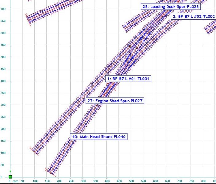
Piece-1 L #01 TL001 is the main track turnout, shown highlighted here.
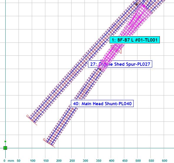
It is a B7 Left hand turnout, the main line centre-line radius of which is -2148mm which is the curve I need to set up when assembling this kit. All the nuts and bolt details will follow shortly over on my workbench
I will then move on to the second turnout which completes the start of the run-around.
 Last edit: by Colin W
Posted
Full Member
Aside from the building of seven turnout kits as reported over on Colin's Workbench, precious little positive has happened recently on the broader layout build. Things have sat dormant since Christmas then some visitors came by (from WA) so Westown-Heathfield was bought back into action.
Breaking news this week from British Finescale caused a minor rethink and reschedule, neither of which fell into in the +ve news zone. I found out that the reported single slip was delayed into April and worse, was now going to be in B7 geometry. This latter caused a minor rework of my plans built around a B6, fortunately the time invested in learning basic Templot meant I handled this task easily.
Today W-H was shunted off to its holding spot and work recommenced. The new plans were printed off, at least the spur to the Tannery and the Traverser approach. Then a couple of bits of track were put on to give a better feel.

I've decided that I'll do nothing much more until I have all the remaining kits safely here. After all "there's many a slip (presumably a single!) 'twixt…….."
PS the exit from the slip onto the Tannery line has the tightest radius plain track in all my plans. ~ 900mm, as the track follows the curving line of the river (to the left, off scene)
Last edit: by Colin W
Posted

Full Member
I am very envious of your immaculate work space after the squalor I am engulfed in with my retrofit extension :roll:
The smooth curves of the sidings look great- so elegant. I cant wait to see the actual track laid.
Best
Posted
Full Member
It's hard to believe almost three months have passed since my last post, other matters of all sorts and various delays both contributing.
The week past, a sudden burst of focus resulted in a trip to Bunnings and purchase of some 915mm * 1830mm sheets of 3mm MDF. Although a tight squeeze into the car I managed to get them home undamaged. Getting the larger imperial sized panels (how quaint) allowed me to cut 428 * 915mm from one end, leaving 1400 * 915 mm panels which were then ripped down the middle to give pieces of 1400 * 456 mm.
By some minor miracle, as I had not planned it, this gave me precisely the required lengths for the sides of the "L" (3 *1400 + 1* 1400) and give a net back scene height of 407 mm since they will sit on the L-frame top. The end off-cuts were also similarly blessed with being the correct dimensions for the panels in front and side of the traverser.
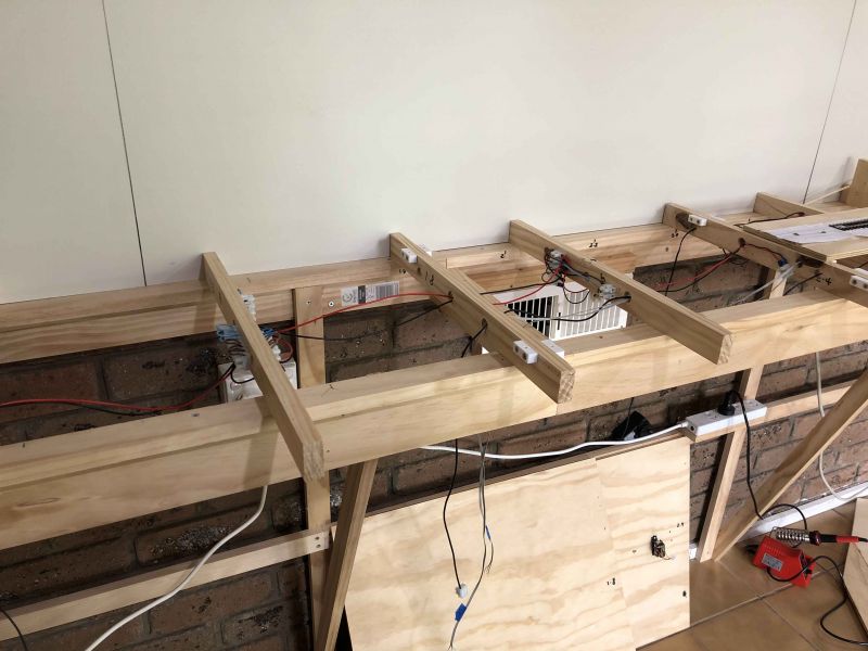
This photo shows the first of the three side panels in situ for testing.
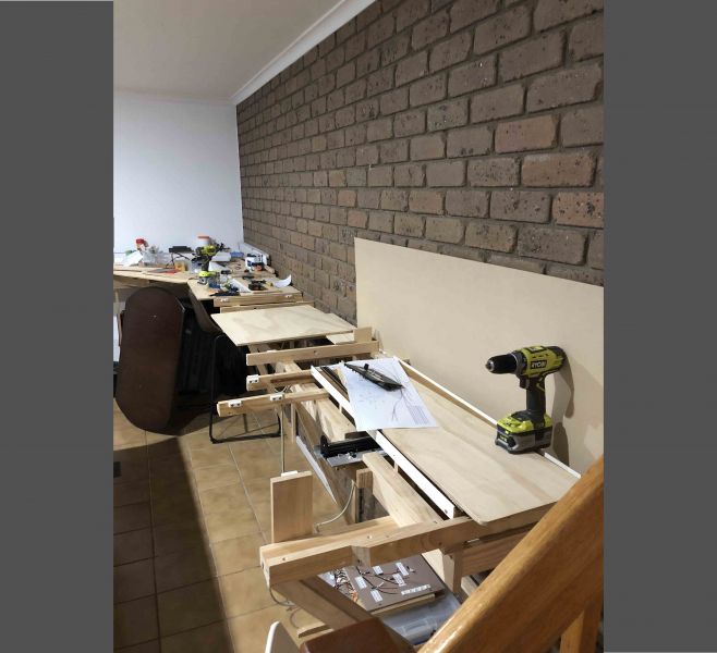
Top panels are in various stages of disarray as I prepare for power bus and turnout control lead access holes and some minor repositioning of the bearers as the plans have shifted somewhat since the Nov build.
Last edit: by Colin W
Posted
Full Member
A very productive winter's day here with rare fine weather when I could do some painting outdoors as well as progressing the mounting attachments.
Three of the back-scene sheets attach to a brick feature wall with nicely rebated mortar channels. Taking advantage of these I made "U" shaped inserts from thin steel sheet as mounting points / field intensifiers. These were glued into the channels and then Neo magnets glued onto the outward faces (bottom of the "U").
The boards had thin strips of steel strip glued in position to fix to their corresponding magnet and the combination works very well, neatly holding the back-scene board flush and tight against the brickwork.
Boards were painted with some left over from an earlier project. This shade proved ideal for my purposes as the base.
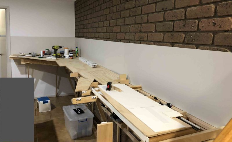
This will work well for me because UH will not be in a sunny summer idyllic setting but a drab ordinary day in late autumn or early winter. It rains a lot here with the Blackdown Hills directly behind and surrounding the village and I'll aim to capture that mood.
Last edit: by Colin W
Posted
Full Member
I've had an inquiry for some more details about these magnetic mounts so here goes.
Recent purchases from the usual on-line sources of neo super magnets have been of hopeless quality when compared to my existing stock. So I went back to an old source of which I have a substantial reserve, old Hard Disk Drives! Pulling the large older style drives apart offers up two very powerful neo magnets and other useful bits and bobs.
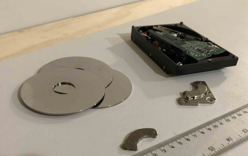
If you have commercial block neos 20 * 10 * 2mm of good quality on hand these will be equally good but in my case I used a fragment of one HDD magnet as shown below.

These magnets are easily snapped (safety glasses essential, see my safety footnote below#) into usefully sized pieces. This one is shown mounted on its "U" shaped strip. The bottom of the "U" acting as a field intensifier (much as in the under track Kadee uncoupler)
In addition to finding magnets of useful size and excellent strength to hold back-boards flush, there were other upsides.

Stylish reflective silver magnetic disks from the drive assembly will grace your table as coasters while ensuring your old e-data does not fall into the wrong hands! (here they catch the pale brown of the Mountain Ash panels of our Family room cupboards as well as the reflection of the glass)
# I have broken many of these into smaller pieces for use over several years and never had a single issue. They are nickel plated to protect the surface but I've never worried to paint over the broken edges where the raw magnetic material is exposed. In more humid climates that is probably a good protection for any exposed magnetic material.
What is a potential issue is working on the magnets. The material is reactive and should not be drilled, sawed or cut using a rotating disk wheel. This may expose the operator to serious hazards. If in any doubt research the safety data info supplied by reputable suppliers of these magnets.
Last edit: by Colin W
Posted
Full Member
I thought fixing the backboards to the feature wall with magnets was extremely elegant.
Now I see you have devised an equally ingenious method of sourcing the magnets :thumbs. I thought for a moment that the alternative use as coasters might have the side benefit of preventing "wine glass side swipe" - but I guess that would be expecting too much

With winter approaching in Melbourne it should not be too long before we see some track laid on Upper Hembury?
Best wishes
Posted
Full Member
With much more room to operate downstairs once the demolition of Westown-Heathfield was complete, first in hand was some long overdue catching up on sorting sensible storage options for both new and old items and some serious indexing so I can find things when needed! This and other less critical distractions meant that progress on the build has remained "just around the next corner" for some time.
That changed this week when I finally worked my way thru the substantial selection of W-H track which had been sitting in a large bucket of water soaking to de-ballast. I had not realised how much track that little layout had required and a further surprise was the discovery of a considerable number of set track straights!
Now I realise the mere mention of Set Track triggers negative reactions in some quarters but it turned out that the exact opposite was in fact the case. Hence the title of this post.
My first task before starting laying track on the layout proper was to lay the 7 roads on the traverser tray. I'd always intended for this to be done with Code 100 flex, a job I was not looking forward to, "7 roads, dead straight, even separation, square ends".
Well the three positives of Set Track came into play, Dead straight, Square ends and track joiners making solid contact and designed to survive a hurricane. Laying the Tray with these was a breeze, then easily wired up and job done.
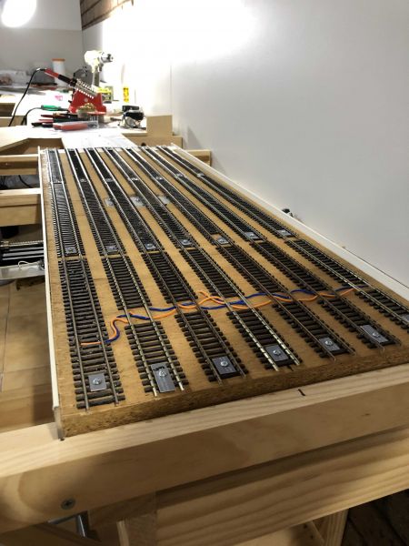
The tray is connected to power via a flexible plugged lead, so the tray can be removed if ever needed.
Last edit: by Colin W
Posted
Full Member
I know it's all done, but I used flexi track and a 1 metre straight edge to lay my storage sidings.
Cheers Pete.
Posted
Full Member
Various key elements have been assembled onto the base board of the panel, starting with just one of the 3 CDU modules so I can test various issues with the operation
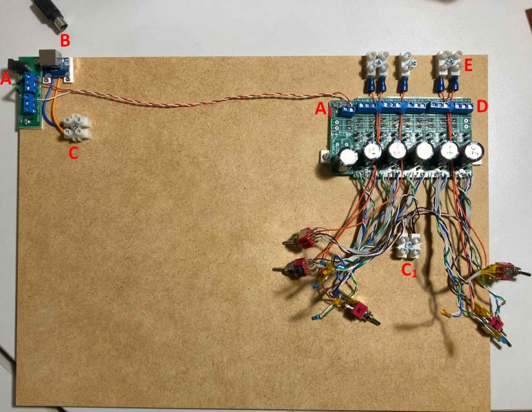
Many of the minor items have been repurposed after an earlier life.
A is the main 15V DC input and distribution board, cobbled together from a defunct circuit board which happened to have useful terminal blocks and a standard 5.5mm Circuit board DC socket.
A1 is the DC power input to the CDU Power reservoir which buffers power to the 5 CDU modules.
B is the DCC Bus input port. I chose to use a DC Jack socket from a very old style external HDD. The socket had to be hacked out of its PC board as it was far too well soldered to undo. The old power brick supplied the matching plug and length of lead. Different plug so no risk of muddling up the input lines.
C / C1 DCC power distribution to the three CDU banks
D Terminals for CDU output lines to solenoids
E Connectors for individual outputs of Frog DCC power lines.
Power to the 2nd side of the DPDT switch comes from C via C1 to the two end pins of the switch (twisted pairs, Brown/ white) with the frog power out (orange) on the middle pin.
Excuse all the great detail but one day it'll help me remember what I actually did!
Based on previous experience. I've used various sources of recovered cable.
Twisted pairs are very handy for colour coding and wiring up LEDs with correct polarity.
DC power lines recovered from old USB cable are heavy enough gauge to handle DCC local power distribution for the frogs.
Testing to follow as I suspect there will be the odd issue getting turnout switching, direction indicators and frog polarity all aligned correctly.
Last edit: by Colin W
Posted
Full Member
With the CDU ready for action I started out laying down the beginnings of the power bus, working back from the traverser towards the Control Centre. While that might seem a tad illogical, it follows the route of my track laying and also ensures the bus is where it needs to be in the peripheral areas rather than trying to anticipate an ideal route from the start.
Track and droppers are going down in parallel and I've reached the critical baseboard segment with several key Turnouts and the Slip.

Installing the slip was always going to be a key step for me as I've never worked with them before, let alone with live frogs and built from a kit to boot! Hence I've been taking matters very steadily.
Last edit: by Colin W
Posted
Full Member
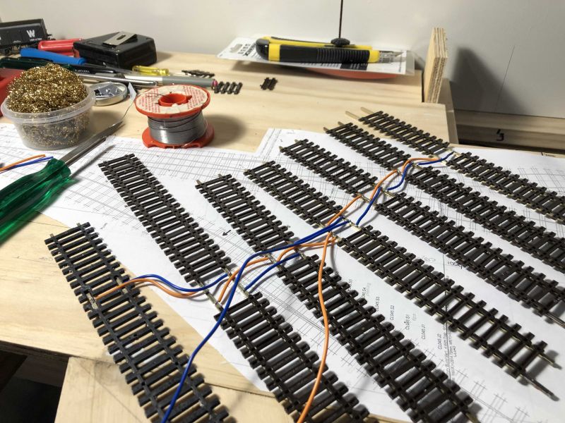
A further couple of kit builds were required for key turnouts comprising the Goods Yard entrance. With these knocked together in not too much time I have the key components ready to be laid.

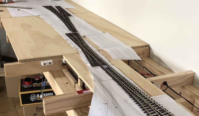
Here they are final position so I can insert dropper holes before the big connect.
The further I get into bringing my track components together, the more I'm finding the benefits and flexibility of working with and joining the Finetrax kits. The ability to lengthen / adjust the entrance and exit lanes helps avoid those annoying short interconnects I found I needed when working with rigid pre-formed turnouts. The curved to curved crossover at the far end is a great example and I'll take a closer look once they are fully installed and connected.
Last edit: by Colin W
Posted

Full Member
'Petermac
Posted
Full Member
Thanks Peter,Those points look superb Colin - if only had had the time and patience to give hand made track a bash - it's so much more flexible and better looking than the bought in stuff. It does however, take a longer than popping an order in to some shop or other and patience never was one of my virtues………………… :roll: :roll:
TBH, with the exception of the slip, the time to assemble a turnout kit after a little practice is not that long. I reckon the upside of having them fitting perfectly to plan is a big offset when compared to the faffing around trying to get set points to combine and give you what's desired. Something I found previously on Westown and John Dew noted when doing his yard extension. As he said at the time……
"Its not exactly as originally planned. The tri-angular site was very restrictive and as the track laying progresses I found myself obliged to add a few inches of track here and there to ensure either clearance or a smooth transition. Each such inch added then resulted in similar loss in the sidings." (18th May)
Then as to the slip, it did take quite some time but I felt it was fully worthwhile, it is a superb bit of kit and a great centerpiece to my station precinct approach.
Posted
Full Member
Cheers Pete.
Posted
Full Member
My early efforts at curving these kits lacked the helpful info posted later by Martin Wynne. His mthod gives a much better outcome with smoother curvatures so as each of the early turnouts is deployed, it'll get the "once over Wynne treatment".
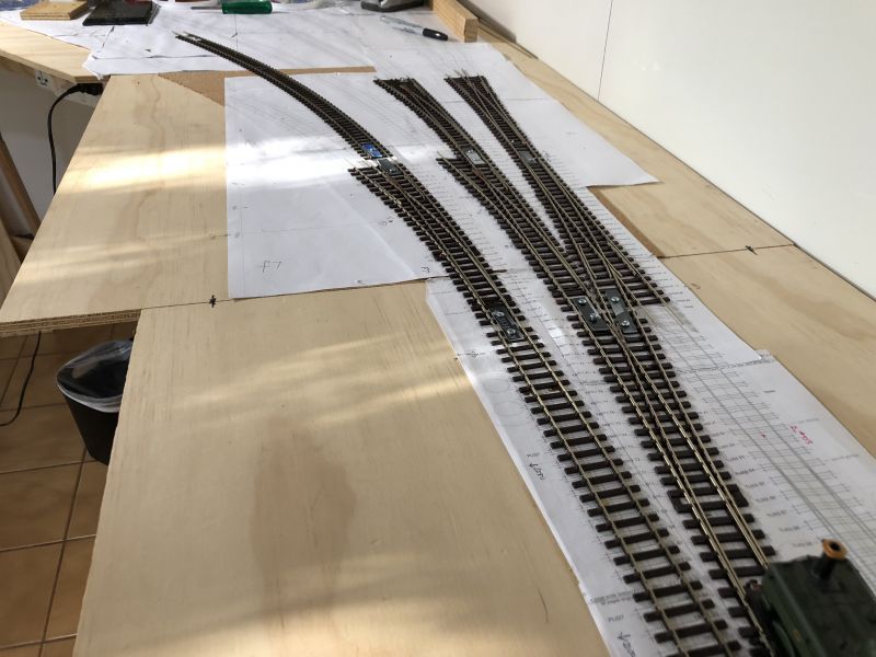
Dropper holes for power and centre holes for solenoids were drilled and the entire set of track as far as the 1200mm point were positioned.
The photo shows the view as a loco leaves the slip by the Goods road. The track to the left leads to the station lines, a proxy for the main platform line has been put down.
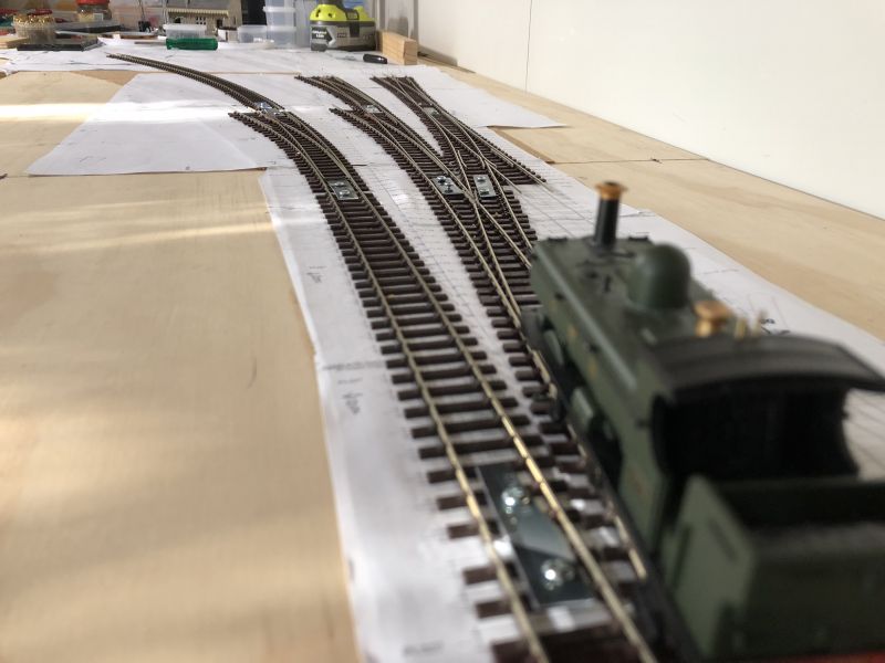
From slightly higher the various Goods lines and the start of the run-around can be seen.
After today's progress, I've increased optimism that I'll have trains running in time for the influx of Christmas visitors.
Last edit: by Colin W
Posted
Full Member
Cheers Pete.
Posted
Full Member
There is no simple answer to this, among issues which weighed heavily was the lack of any local support here for Tortoise (in Melbourne), or for that matter these days any other model railway technology. Even DCC Concepts have relocated to the UK. Also, as you've found, the ever increasing challenges of depending on sourcing / support from the UK. If I buy anything technologically based, I've a higher than average chance of hitting problems, ask me how I know!I really do like your kit built track, but after taking all that trouble, would you consider using Tortoise motors instead of solenoids?
There are plenty of high quality show circuit layouts, "Shap" for example built in Code 75, that use solenoids and it was a technology I was comfortable with / locally available if required. It's easy to have a few spares in a drawer.
When I found I could integrate turnout and frog control and direction indication based around locally available CDU technology that sealed the deal for me.
The sting in the tail was to learn after the event that there can be an issue with solenoids on the lightweight Code 75 in the design used by Finetrax. Subsequent comments from the company's owner suggest this is not a deal breaker, just a potential nuisance down the road.
I'd already taken steps to downgrade solenoid force by dialing back on the CDU voltage to 15VDC, providing some additional resistance to the solenoid pin (adding a non functioning PL-13 accessory switch). I have a regulated adjustable PS which may allow me to go a little lower yet with the voltage. I have options up my sleeve!
To switch now would be a very wasteful / expensive / delaying exercise so I'll just see how I go. It always remains a fallback option should need arise.
Last edit: by Colin W
Posted
Full Member
Having rambled on about that I can see where you're coming from.
I had a large layout under our previous house and built a cdu hefty enough to throw eight points in one go. Needless to say I had to put resistors in for single point motors.
Cheers Pete.
1 guest and 0 members have just viewed this.