Upper Hembury GWR Branch Line
Posted

Full Member
Updated plans and now moving ahead
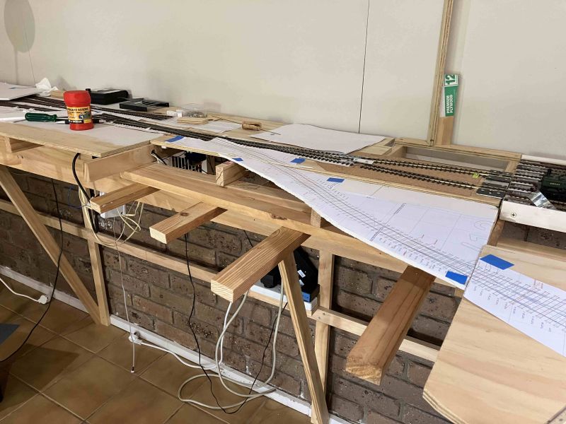
And then more progress on the traverser end with the additions of the scenic screens but not before I'd realised that I needed a little more Real estate out front, hence a revised plan of traverser end allowing 430mm at the widest point —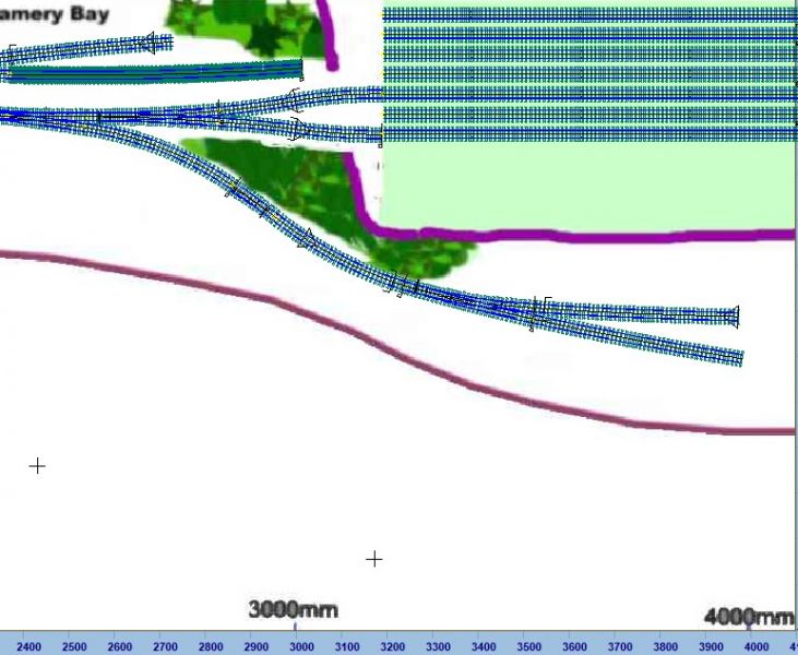
This required minor modifications of the support structure, easy with this style of frame.

and then the expanded top surface.
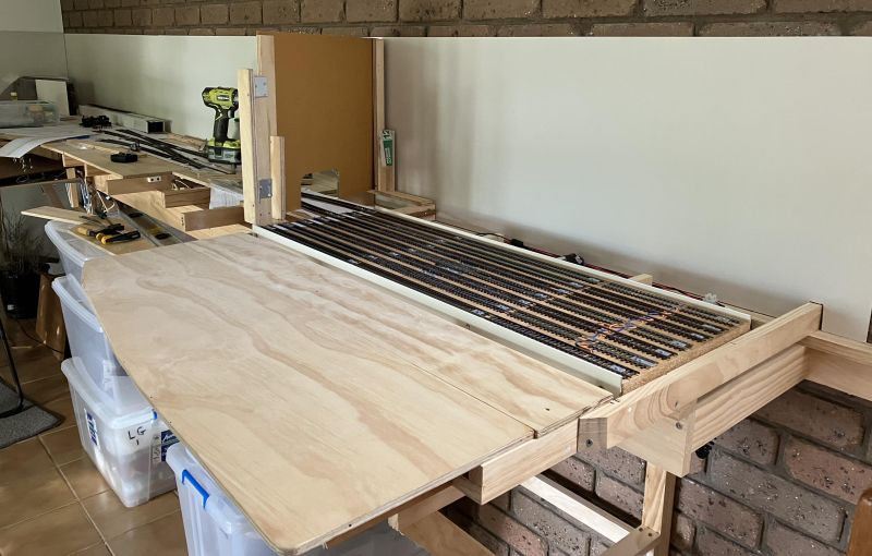
seen with the backboards in place:
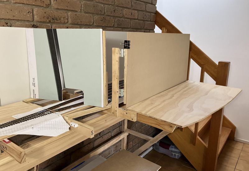
I've been asked about access. Hard to see from the above but there's easy access at the far end and the front (exit) panel will be removable.

Posted

Full Member
Great work and well thought out.
Posted
Full Member
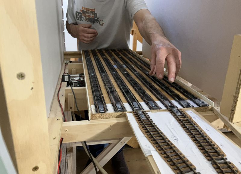
Now P&Q has returned and we've recovered a little, I've turned my attention to checking and fine tuning the Storage traverser. As my grandson J (12) reminded me, I have a lot of independent variables to manage here, tricky.
Key points:
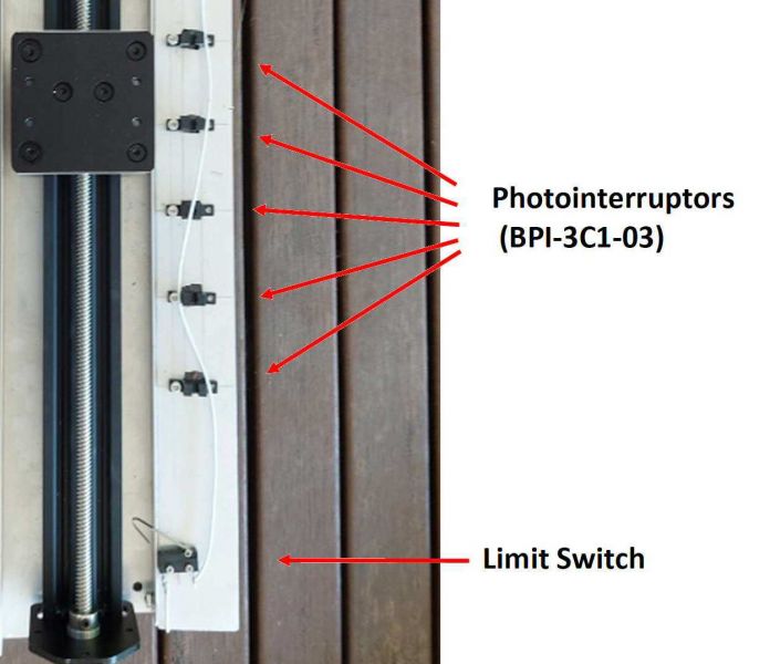
1) the traverser tray movement is controlled by a stepper motor stopped when a thin wire (not shown) reaches a photo-interrupter. These are positioned to match track separations but can be manually fine tuned individually. The screws allow for a rotation which moves the sensor point very finely to 0.1mm
2) the tracks were adjusted to give the same separation, a length of spare rail cut to length served as a handy tool.
3) The approach roads needed to be held perfectly in line and at the same required separation but retaining ability to adjust the pair sideways for fine tuning. This was done on a 2mm aluminium mounting plate.
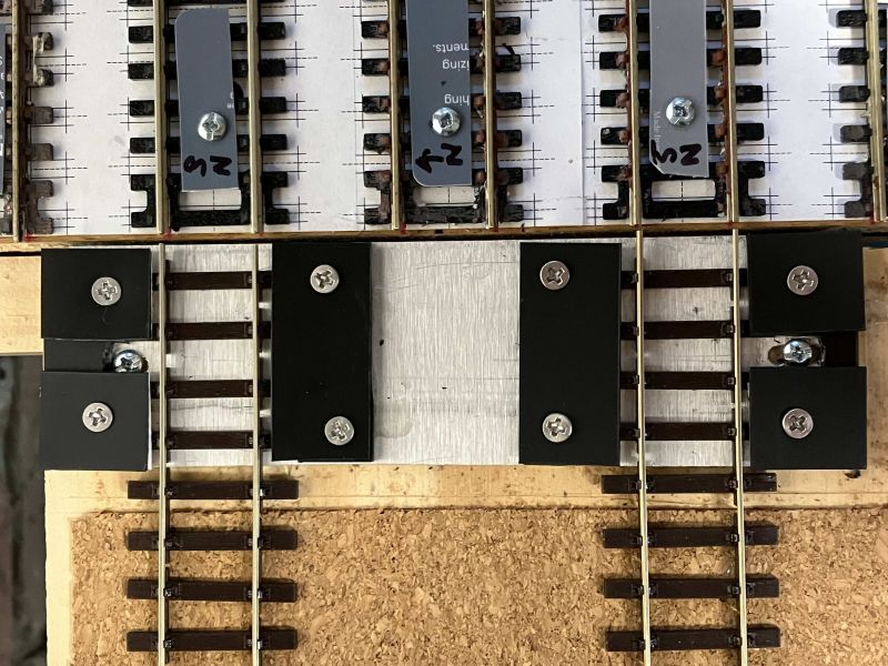
It ended up being an iterative process to get the sensor positions and the approach roads to optimum placement.
I knew there would be a minor difference in the tray stopping positions between forward and reverse movements, i.e. the wire approaches the sensor from opposite sides. The fine wire has a finite width and on the drive assembly under test this led to ~0.3 to 0.5mm variation in the stop points between the two movements. It was rewarding that when assembled and tested the equivalent variation measured as <=0.5mm despite the tray being centre driven and hence the edge is 460mm from the line of drive.
My 2-6-2 Small Prairie with its free floating front / rear wheels is the most demanding of alignment but when fully aligned it worked well on all lanes, as will be seen later.
The traverser drive and control system were designed for me by my very good friend Graham Jackman and it is a piece of work I'm deeply grateful for, especially now that it has fully shown its worth in action. He has had his design published in Silicon Chip who hold the copyright. Those interested can see it at p92 of the December 2022 edition.
Posted
Full Member
Traverser Video 1
The second shows 4539 moving from the runaround track across two curved B7 left turnouts, onto the B7 Single slip and then a B7 Right turnout (converted to a "Y") in the storage access approaches.
Traverser Video 2
PS I've edited this to add back the Youtube links and remove all the font and spacing formatting info which has come over with the Site transfer. Hoping that tidies things up. Links to Youtube work very well in new format :)
 Last edit: by Colin W
Posted
Full Member
Cheers Pete.
Posted

Full Member
Looks fantastic Colin - so clever. :thumbs
'Petermac
Posted
Full Member
Traverser Operations
My plan has been to have three possible options for loco and stock movements happening "off stage", exploiting the features of the design
1) Loco runarounds.
I've been advised that Branch operations such as Main (GWR Cullompton or SR Sidmouth Jct.) heading to Branch, Upper Hembury would operate with loco heading on the Down, running around, then returning on the Up heading the train in reverse. It not being usual to have a turntable at the small Branch terminus.
Hence, the returning loco needs to complete a 2nd runaround while at the traverser and today's post looks at my plans being tested out in the flesh. Fortunately the cassette mechanism from my previous layout was readily converted to use on UH, simply setting the approach angle to head on, a few quick cuts and you have a working cassette
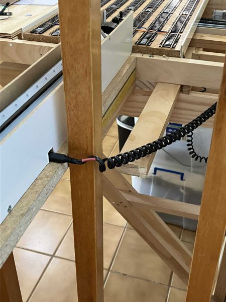
As the cassettes were already pre-wired, I just needed to connect the flexi-lead into the bus and plug in.

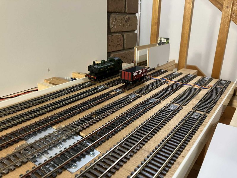
The loco was backed into the cassette and the combination shifted to the access point on track 1

The loco pulled off perfectly, ready to go out onto the approach road and complete the runaround procedure. This was a simple case but to access a free track, it might be nescessary to move the traverser tray to bring a free line to a cassette loading point.
At present, the support connections to the end of the layout are temporary, to enable testing. I'm not planning to have permanent fixed lines there as the cassettes option offers much more flexibility.
Posted

Full Member
I am a firm believer that storage is the key to a good layout. Your traverser offers 6 trains and multiple loco options - more than enough to give the terminus a wide scope of traffic and operation. Excellent!
Barry
Shed dweller, Softie Southerner and Meglomaniac
Posted
Full Member
2) Rotation of Stock (head to tail)
Not likely to be much used but the storage cassettes are easily rotated and are powered for operation in either direction
3) Loading Stock from a long Storage cassette.
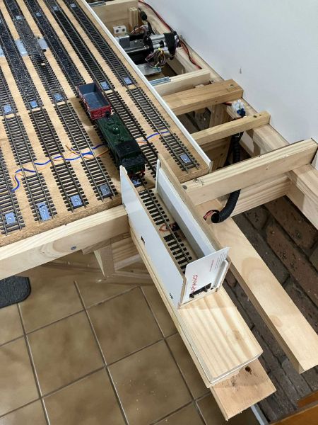
I have several of these, about 760mm long from the former layout but loading them with just a 300mm gap and a banister beyond created several challenges
How to make a secure loading platform which did not compromise my access space at the traverser end? I drew on those old interlocking wood puzzles for some inspiration.
The horizontal slats will hold a load if they are inserted into the end and under a second joist, fine but this makes them over 500mm long.
The second challenge was fitting them between the balusters and then locking in place.
My solution is best understood by seeing it in reverse, dismantling is a very rapid process in pics 1-5 below, leaving the access space totally clear.
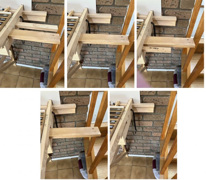
1) pull out the narrower rear support, this comes straight out between two balusters to give (2)
3) pull out and remove the concealed key (access from beneath) this has locked everything rigid once assembled.
4) rotate the front support towards the user so it can be removed between the two balusters to give 5)
A simple lock allows a long support to be laid on top of the forward support and this in turn takes the Cassette.
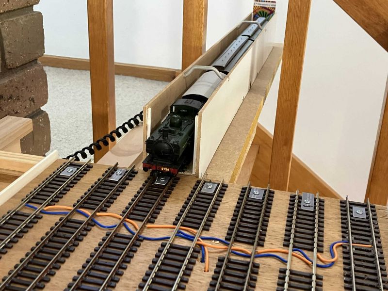
easy access and removal makes it a convenient loading point for stored cassettes
Last edit: by Colin W
Posted
Full Member
From my teens in Somerset, my strongest memories of Branch line locos were those of small Prairies and Class 48xx, the latter on the Strawberry Line from Yatton down to Cheddar and Wells. So those locos went high on my must have list once I got serious about Branch rather than mainline operation.
The short version of my mission to get a "decent" Class 48xx goes as follows:
March 2017 - Avoiding the Hattons / DJM release, simply enough by reading of the many problems being encountered soon after release, problems which, as far as I could tell were a triumph of design style over substance. OK if you want you loco in a display cabinet but not if you want robust operation.
Next, exploring the issues with the various Airfix / Hornby releases led me to trying out the late 2017 model (R3589) which promised some improvements, albeit in the same 40 year old bodywork. It was not to be, a variety of issues listed and explored here New Hornby 14xx finally convinced me to move on, the Saga continued.
Next up was a 2008 Hornby release (R2778) conveniently sporting the GWR Monogram, numbered "4869", perfect for my needs and I got lucky by finding a rare fine working pre-owned version. It's only limitation was the dreaded traction tyres which on a loco with 4 wheel pickup# reduced effectively to 2 was a problem in need of fixing.
The recommended solutions,
1) buy spare Hornby wheel set (permanently out of stock) or
2) an old dud Airfix model as a donor for a replacement axle.
Selecting the latter my story then took on a decidedly interesting twist!
A suitable dud Airfix was duly purchased, just 8 quid I recall, but when it arrived, it most clearly was not what it claimed to be. Some poking around and questions on line identified that I'd acquired an old Kays 14xx kit, lovely body but dodgy motor with a short, front end half chassis. I can't remember who it was but some kind soul suggested this would be a great project where I could build a decent chassis and get a fine working model. You'll note of course that I still didn't have a replacement axle for my 4869.
This brings me to early 2019. The details are now blurred but Doug Newton and I were in contact and as he lives about 7km from here he kindly offered some help should I go down the kit build path. Lots of helpful advice followed on what I'd need and after some reflection I figured I'd give it a try, put together the necessary orders and awaited their arrival.
This is a good point for a break, because that's exactly what I had, just two months shy of 3 years in fact, thanks to COVID. Doug and I met up for the first time just Friday last. TBC.
# It's true the trailing axle has pickups as well, but as far as I could tell these were close to useless. Earlier versions of this model used plungers on the back axle but these in turn had their own problems.
Last edit: by Colin W
Posted
Full Member
The main change has been the swapping out of solenoids from the main turnouts that'll take the majority of traffic movements and replacing them with Cobalt Omegas. The Cobalt motor here has two sets of inputs, in this photo the upper three are 15V power from the Control panel + feedback line for the direction LEDs and the lower three (S2) are the Red/ black from the Power bus and the Orange feed to the powered frog.

I'd been told that soldering connections to tortoise motors can be a pain, get it right first time and the wiring connections fitted on the cobalt make hooking up a breeze. Mostly done with the boards up, but even the odd one in situ didn't present me a problem.
This photo shows the 1200mm to 2400mm section of the baseboards where much of the more complex track-work is located.

This section is now complete, the latest addition being all the power feeds on the LHS, going to the six lines heading North to the Station / Goods Yards. Everything DCC is wired back to the main Bus so that the boards can be lifted as shown, should the need arise.
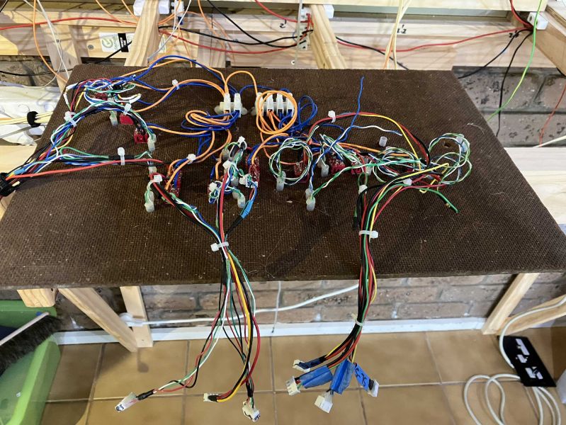
Meanwhile the underside of the mimic panel is much tidier in the Mark II version. Many LEDs required rewiring to work in the Cobalt feedback lines so I took the opportunity to improve the mounting, installing each LED in a small polythene tube which holds it firmly in the panel, but is removable. These can be seen here rising up out of the underside of the board. The groups of three lines coming from the board are the power 15V +/- and feedback via the LEDs. Each of these has a JST plug connection to facilitate complete removal of the mimic panel as required.
Posted
Full Member
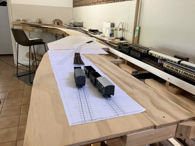
- I completed the installation of 10 uncoupler modules, most importantly those on the main line (3) and one at the back end of the run-around loop together with all the required wired up track.
- The setup was tested thru a multi-step shunting routine
- Pickup Goods comprising 3 vans and 4 wagons plus brake van were pulled from the traverser to the Upper Hembury main Station line (nearest camera), this to commence a test routine involving shunting off the Main
- The loco backed up to uncouple the entire train (uncoupling location is just beyond the fouling point of the crossover)
- The loco pulled forward clear of the crossover then ran around to re-enter the main line at the far end
- The loco then pulled forward, attached to the Brake, moved so the brake then uncoupled from the rear cattle wagon
- The loco and Brake reversed up to clear the single slip and then forward via the run around, to drop the Brake Van in the Main Spur where it was decoupled and parked
- The loco then went back reattaching to the rear of the vans, pulled them back clear of the slip then forward onto the runaround loop where they were uncoupled as shown
The Brake will not be parked in the Spur as shown but at a suitable hold location in the yards, to keep access free on the main. These compromises were necessary as the required lines are yet to be laid.
The home built uncouplers worked faultlessly which is more than can be said for the operator who is still coming to terms with using / controlling electrofrog turnouts!
Posted
Full Member
Suddenly it starts to look more promising.
Posted
Full Member
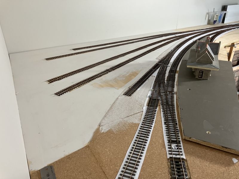
There have been minor updates made to the tannery end from the original plans I posted. I've added a piece of temporary foam board for the corridor from main to tannery, also the updated plan now shows a short spur added to allow for the possibility for a small works engine. I believe that Much Murkle Mark 1 had a similar spur but it later was removed.
Presently the board dividing the storage yard from the tannery is removed but will form the back drop to the factory works in half-relief running along its side.
The trap point in the works line is shown in its position.
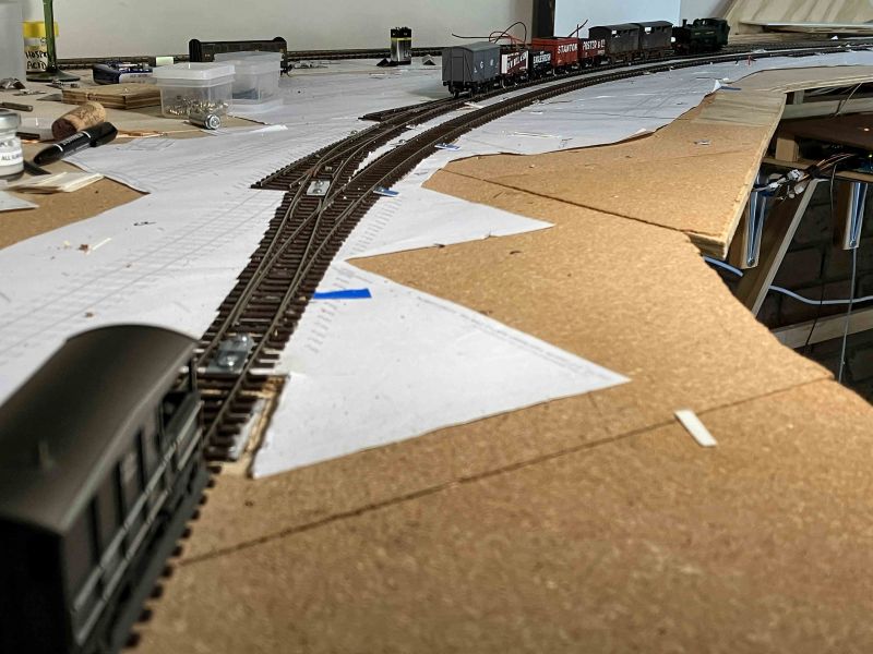
I realised that progress with laying the trackwork out to the Tannery required me to sort out what lay in front of that section of track first.
Earlier in the planning I showed the OS 1881 25inch map of the river and town prior to arrival of the railway. This is repeated here:
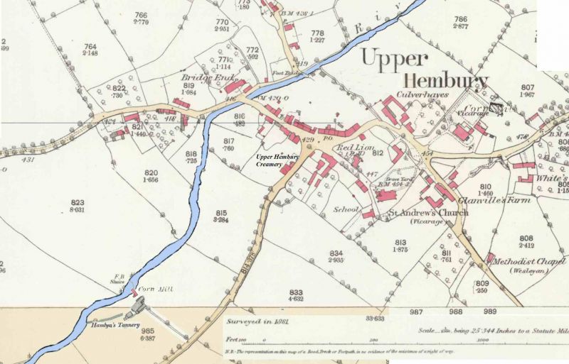
My plan was to model to the river bank all along the front of the layout, dropping down from the higher level of the river bank where the GWR tracks were to be located.
Above the tannery and drawing from the same water resource where a weir closes off the river, there is an old corn mill which I felt would be worth capturing. As a result I've busied myself with constructing a lower tier as a base for the river bank structure. This is the first step in the process.
The track will not cling perilously near the edge, it just looks that way until I build up the connecting infrastructure which will connect the upper and lower levels.
Posted
Full Member
Posted

Site staff
Colin W said
Just checking in with a test post. Looking good so far
From “Post #286,981”, 30th March 2023, 7:33 AM
Colin W
Good to see you made it back in Colin 🤝 🙃
Cheers
Matt
Wasnie me, a big boy did it and ran away
"Why did you volunteer ? I didn't Sir, the other three stepped backwards"
"Why did you volunteer ? I didn't Sir, the other three stepped backwards"
Posted
Full Member
Barchester said
Colin W said
Just checking in with a test post. Looking good so far
From “Post #286,981”, 30th March 2023, 7:33 AM
Good to see you made it back in Colin 🤝 🙃
Cheers
Matt
From “Post #286,987”, 30th March 2023, 8:39 AM
I must say it's all looking very $exy with the new features :devil:
This should be a huge shot in the arm for the old codger!

And nice touch to still have Peter Mac's fav old emoticon still around

PS I mean YMRC not Peter just to be perfectly clear about my 2nd point!
Posted
Site staff
Oh ! You WEREN'T talking about
Petermac
Cheers
Matt
Wasnie me, a big boy did it and ran away
"Why did you volunteer ? I didn't Sir, the other three stepped backwards"
"Why did you volunteer ? I didn't Sir, the other three stepped backwards"
Posted
Full Member
'Petermac
Posted
Full Member
Can't add an emoji because I'm on my tablet but I'll have a field day when I use the PC…….
'Petermac
1 guest and 0 members have just viewed this.