Mike's late 80's BR layout
Posted
Full Member
Trains, coaches, wagons went over but the large space between the break in the rails just worries me.
So, after a bit of thinking I'm going to make a radical change now before I move on.
The rear facia where the door is, on the track plan, there is about a meter where all the tracks (planned 5) will be straight
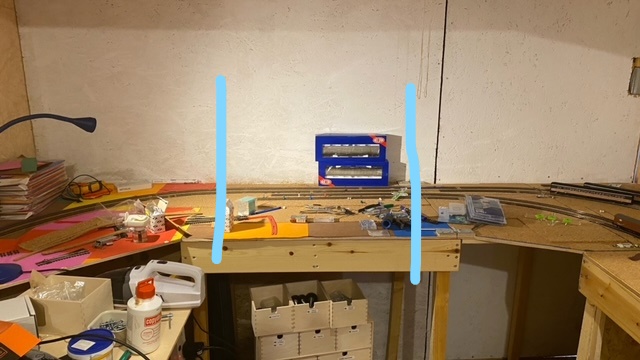
So, my plan is to move the door to the center and have the lift out section where both section cuts in the tracks left and right will be cut straight.
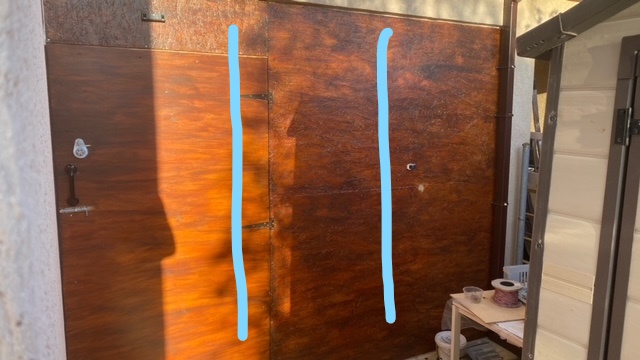
I contacted the chippy who helped me build it. It won't take much work, I have spare wood and support beams and it should take a day.
The layout will then resemble a horse shoe as I don't plan on scenics for the new lift out.
Bit extreme especially as I don't have derailments but I know it will bother me if I don't do it and I'll just be always wondering, "when is this going to fail"
What do you think? Hopefully the right decision. After a step forward I'm going to have a few steps back (yet again) but I think I'll feel more confident with the lift out going forward.
On a final positive note, we had (for round here anyway) a pretty strong earthquake last night.
First one I've been concerned at as pictures fell from shelves and walls and when I went round the outside of the house to check everything, the shed and everything in it was all in tact so at least I've built things sturdy!
 Last edit: by 1867Adelphi
One day I'll settle on a trackplan….
but likelihood is it won't be today!
but likelihood is it won't be today!

Posted
Full Member
Posted
Full Member
I probably should have said my concern was the width in cuts in the 24" radius curve on the very edge of the board.
On a straight, the gap between rails (not the gap between cut sections) is just the normal gauge distance 16mm(?). On a curve, that distance between the rail solder points is greater - in my case 35mm and for some reason just worries me more.
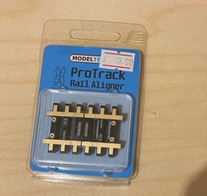
If I do the draw bridge just with straight track being cut, I can also use the Protrack Rail Alligners which people seem to rave at as they look better than the solder to brass screw or PCB board methods and they have an interlocking feature to make them more reliable.
Decisions decisions!!
Last edit: by 1867Adelphi
One day I'll settle on a trackplan….
but likelihood is it won't be today!
but likelihood is it won't be today!
Posted
Full Member
If you check out my page on Teasel I’ve just attempted the PCB method. I’m still perfecting it but I think it’ll work. One of them is on a curve which straightens briefly for the join.If I do the draw bridge just with straight track being cut, I can also use the Protrack Rail Alligners which people seem to rave at as they look better than the solder to brass screw or PCB board methods and they have an interlocking feature to make them more reliable.
Decisions decisions!!
Posted
Full Member
Year right!
Took the panels and door off and started reworking the A frame and the heavens opened whilst everything was exposed!
Couldn't make it up!
Stapled some dust sheets to enclose it and booked a day off the next day to try again.
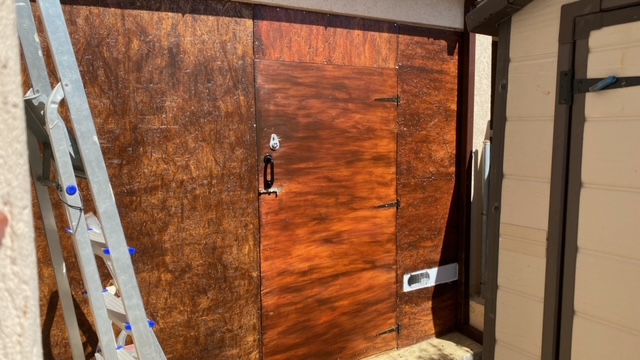
Nice and sunny! Few hours later the door was central and I then spent a week or so rebuilding the back baseboard sections and draw bridge.
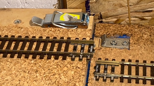
I did take a bit of extra time installing a new vital addition!
I now have Air Conditioning!! :)
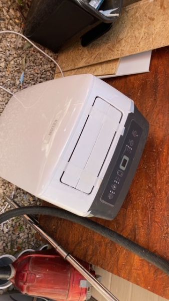
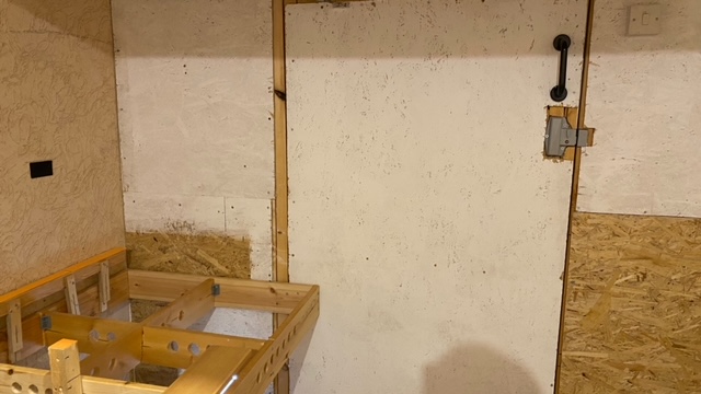
It hides under the baseboard to the right when you go in and the vent tube is long enough to pull it out into the entrance section where the draw bridge drops.
The vent section I cut into the frame panels so it's permanently connected. Should also provide heat in the winter if needed.
Onto the rebuild.
So pleased with the reworking.
The draw bridge works and fits better, more snug and all the things I could have done better with the first try worked brilliantly this time round.
Whilst working on the structures, I was eagerly awaiting a delivery of Pro Rail Aligners.
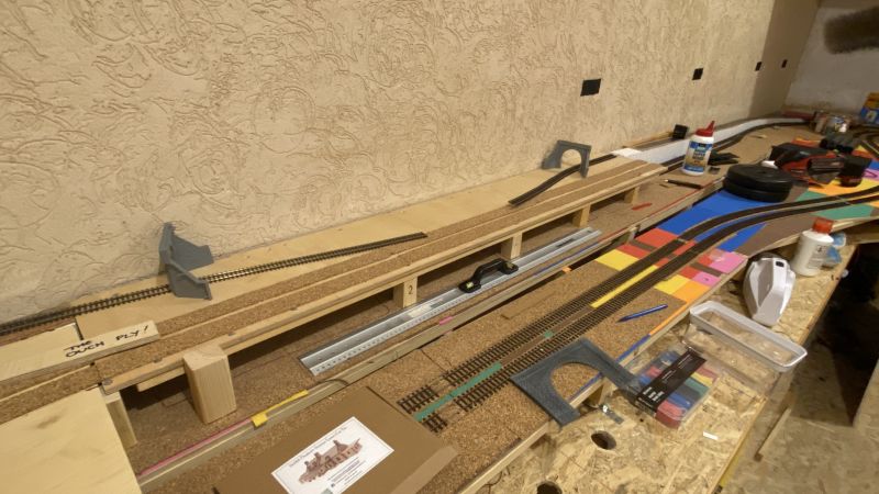
These arrived on Friday so today I got stuck in trying them out with the first of the 5 tracks that will pass over the lift up section.
For a lift up, lift out or modular section, I can't recommend these enough. First one was a doddle to fit and works so well.
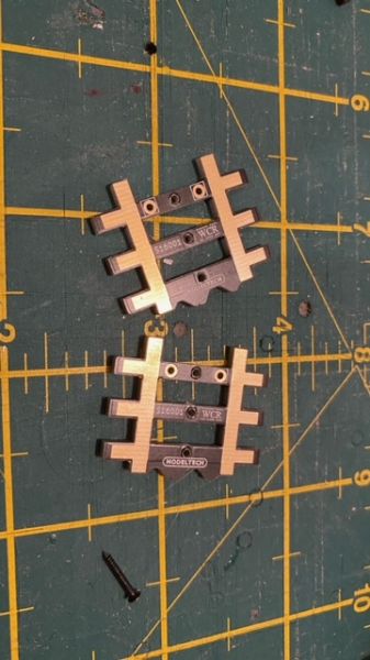
They have a "teeth" side section which interlocks with it's other half.
You remove 3 sleepers from each side and solder the rails to the PCB.
I used a bit of adhesive to align correctly under the rails on my workbench before soldering.
The units come with holes for droppers and holes for track pins.
I use the Piko screw pins so I had to make the pin openings a little bigger with a small bit from my pen vice.
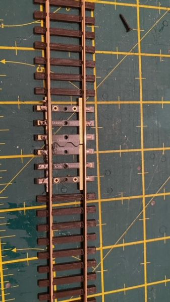
Once I'd got both sections laid I took it over and secured it to the lift up draw bridge board with the boards fully locked together with the clips.
With both the left and right overlap sections correctly secure and straight, I cut the tracks with the dremel.
If I then released the clips, the join opened slightly allowing for movement with the lift.
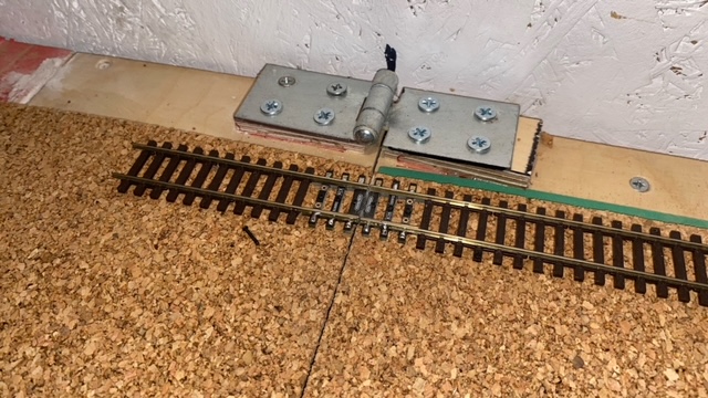
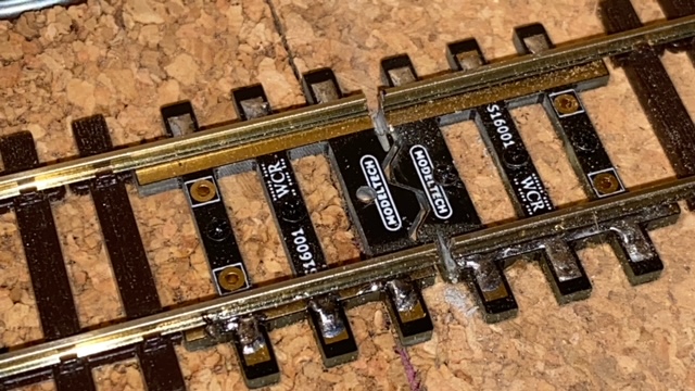
Forgive my dodgey soldering… if it's any consolation, I am improving!!!
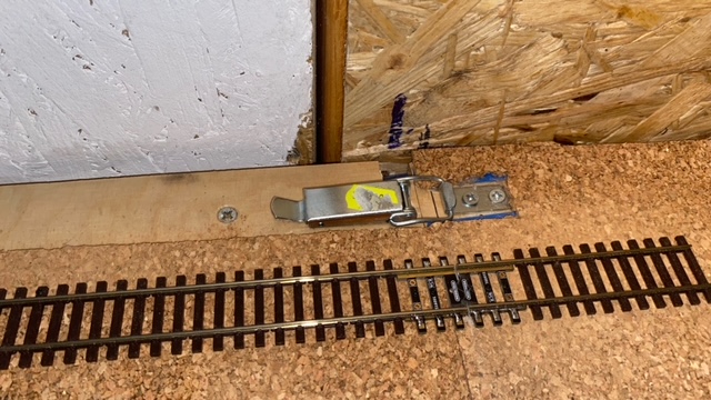
The instructions for a lift up state it's best to overhand the units to rest on the opposing side. (as above)
If this was modular, they would just butt up to each other.
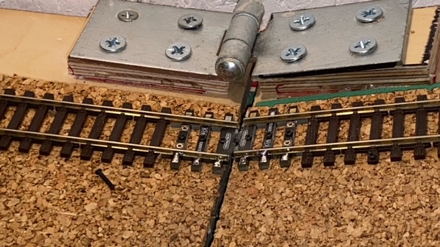
The rear just needs the join to meet over the join in boards.
It works perfectly, the coaches I tested ease over.
Nice when something works!!
So, the next track in from this one is the one that completes the circuit so I'm hopeful to get that done in the next couple of days, have a night wiring droppers to the bus and then hopefully get trains running again!
Oh yeah, before I go, quick update to my spending addiction!
Apart from the Pro Track Aligners (a real bargain at £10 for 4 pairs) I'd not bought anything since the beginning of April but unexpectedly, I found 3 TSO Mk3 Inter City coaches (2020 tooling) from KMS Railtech so I quickly snapped them up along with 3 of the newly released Mk3 Swallow livery sleeper coaches.
Just need a restaurant coach and that'll complete the train for the Swallow HST power cars.
Soooo tempted with the newly released Hornby GNER class 91 as I just love that blue livery with the red stripe but I've resisted so far… some mixed reviews from various youtubers giving me a bit of caution but I'm sure my resistance has the breaking strain of a soggy kit-kat so doubt the credit card will stay cool for long!
All in all, happy days, mojo returned and I just hope everything is layout related from here on in and not reworking the shed itself!
One day I'll settle on a trackplan….
but likelihood is it won't be today!
but likelihood is it won't be today!
Posted
Full Member
Posted
Full Member
Better than the first effort anyway! :)
One day I'll settle on a trackplan….
but likelihood is it won't be today!
but likelihood is it won't be today!
Posted
Full Member
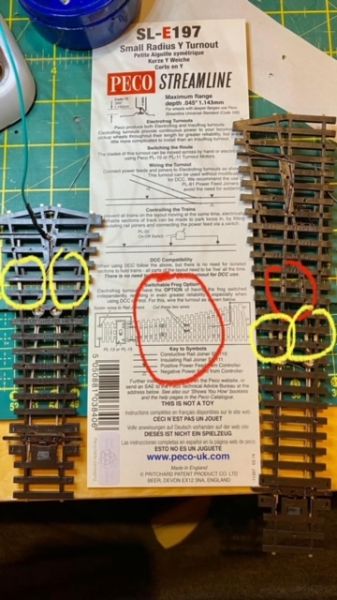
Bit of fault finding and it's the small "Y" point.
Bit of peco brilliance. The instructions on the back are for a standard point and the usual modifications to do (cut the little wire, bridge the rails etc.
There's no cut in the rail so thats causing the short.
Posted some things on a group and most people said its easier to just use a different point but I'm going to try to do the modification and manual cut of the rail
 .
.I'll give it a go. What's the worse that can happen? small left hand normal point on standby lol!
One day I'll settle on a trackplan….
but likelihood is it won't be today!
but likelihood is it won't be today!
Posted

Full Member
You'll need to have a switch for the frog polarity.
'Petermac
Posted
Full Member
It's a known problem with the small radius Y turnout according to RMwebThe instruction card is written exactly like a normal left or right turnout as you can see, even the diagram is of a point rather than a Y.
The isolating cuts that are usually just before the frog section are missing meaning if you don't perform your own corrective measures, it shorts!
For the time being I've removed it whilst waiting for some online help! - Someone is going to send me pictures of where to cut the isolating section and where to add a wire to the frog to solve the problem.
Sods law that wasn't my only short!
I fault found to a small right hand point which will lead to a siding along the back straight and after removing, I'd foolishly not cut the tiny wires built into the point before modifying for DCC.
2 little snips later everything was up and I've spent the rest of the night finally playing trains.
Kid number one just wanted to press the horn all night, kid number 2 wanted to get it fast enough to be able to go back in time!!!
No derailments though, especially at speed over the lift up drawer bridge. So pleased with those rail aligners!
Need to do some homework though, first loco up was my HST Swallow and I need to learn how to set the decoders up for back to back running together.
This was a second hand set from ebay (although far from second hand price!) and the former owner just reverted the decoders to default 3.
I'll have a look on the hornby site for the TTS sound instructions as I can't see any "how to" guides on YouTube.
I'll work on the station platform loop tomorrow then get to work on the two lower mainlines which will be the focus of the coastal section (blatantly inspired by Teasal Bay lol)
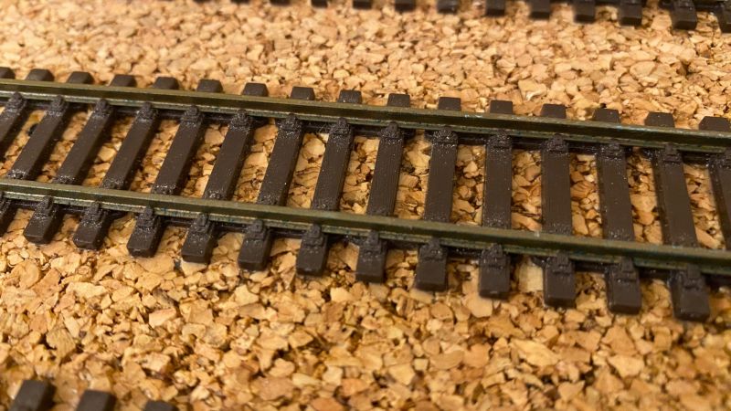
Had a delivery of bullhead track so no messing around with sleepers to a more prototypical spacing
Last edit: by 1867Adelphi
One day I'll settle on a trackplan….
but likelihood is it won't be today!
but likelihood is it won't be today!
Posted
Full Member
I too have made that same mistake forgetting to snip the little wire then spent hours scratching my head and using stronger language than normal looking for the short ….
Good luck with sorting the HST decoders. :thumbs
'Petermac
Posted

Full Member
Sounds like a power routing turnout where the blades provide the current to the frog. Where you make the cuts in the closure rails depends on how long a frog you want. It can be 1.5" or less. I usually use a Dremel with a cutoff disc. The gap is enough to provide electrical insulation. I can send by pm a diagram if you want but DCCwiki explains it very clearly. DCCwiki.com/PECO_electrofrog
Nigel
©Nigel C. Phillips
Posted
Full Member
Took a break this last few days to learn the art of Adobe Permier!
Work have unexpectedly said we can replicate the additional "stand down" day given to military folk tomorrow so a last day off and back to laying track tomorrow!
One day I'll settle on a trackplan….
but likelihood is it won't be today!
but likelihood is it won't be today!
Posted
Full Member
Steady (aka slow) progress over the summer and autumn. I seem to make one step forward then one or two back!
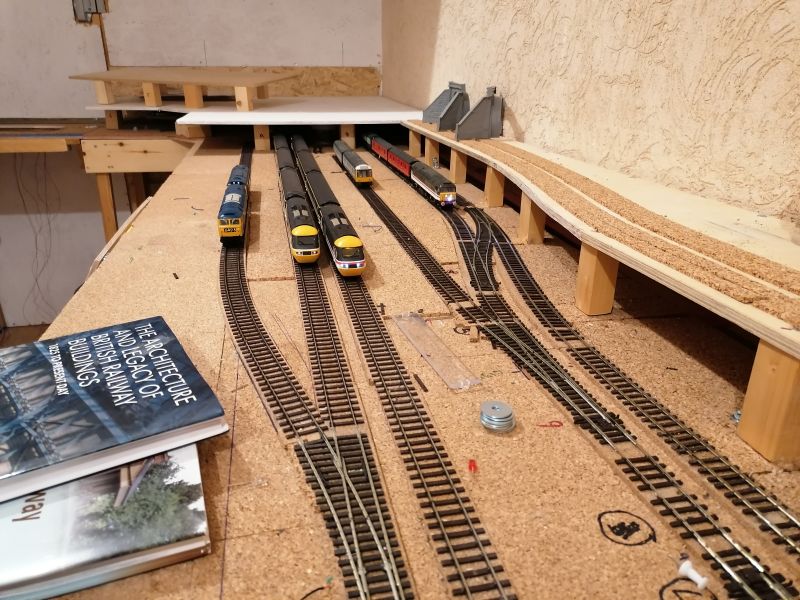
Ironically, seeing the above post on the Y turn out is quite fitting as I replaced it this last weekend with a large radius equivalent. It was making for a tight turn into the bay platform with frequent derailments.
So…All the lower track is now finished and I'm happy with.
The main delay was getting electrics and sensors sorted to the track that will be hidden by the upper section or scenery.
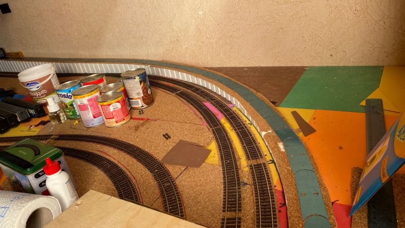
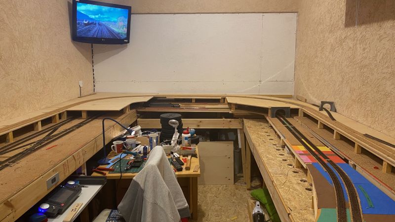
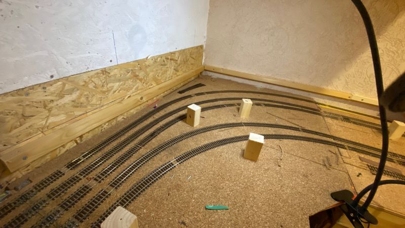
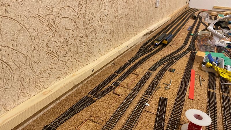
Quick look around.
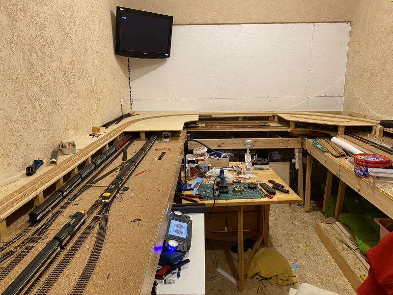
Apologies for the mess but I just CANNOT keep everything tidy! This is as good as it gets!
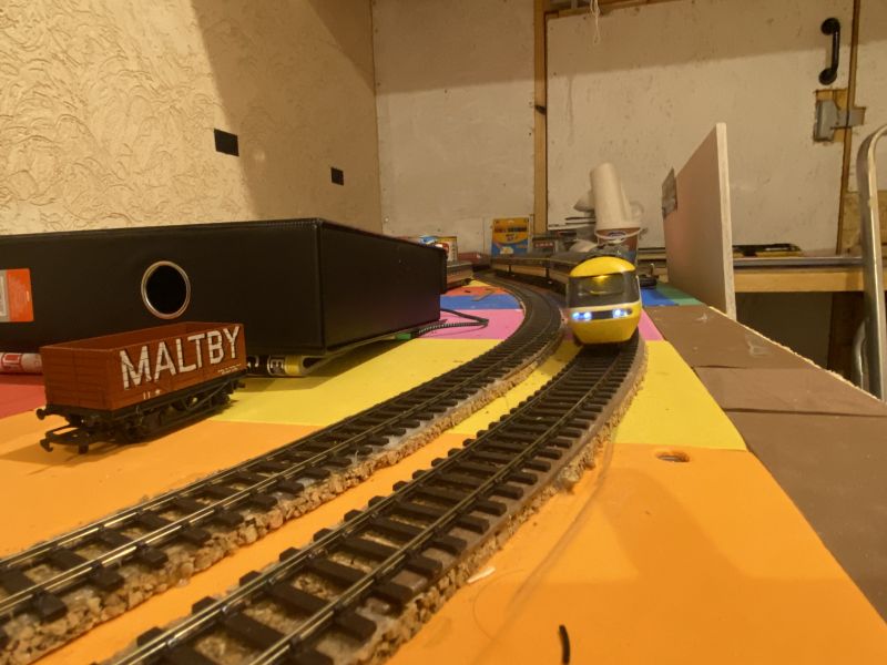
So - Left hand side is where the main station will be leading out past the throat into tunnels. The left line (currently occupied by the parcels train) goes to an incline to the top section.
Line next to it is a loop around the layout which will be hidden pretty much which will also hide a storage siding.
That leaves the two lower main lines.
To the left of the station will be the upper main lines.
Under the upper section I had laid track which goes down to a lower storage section. The lower decent line has been laid but I'll be taking this up, recovering and having 3 long storage lines.
Having the lower storage was going to be just too complicated and given my progress the new idea is easier.
I'll be able to access/view the storage lines as I plan for the retaining wall between top and lower to be removable using magnets.
In low relief next to the lines of the upper loop will likely be either factory or residential properties.
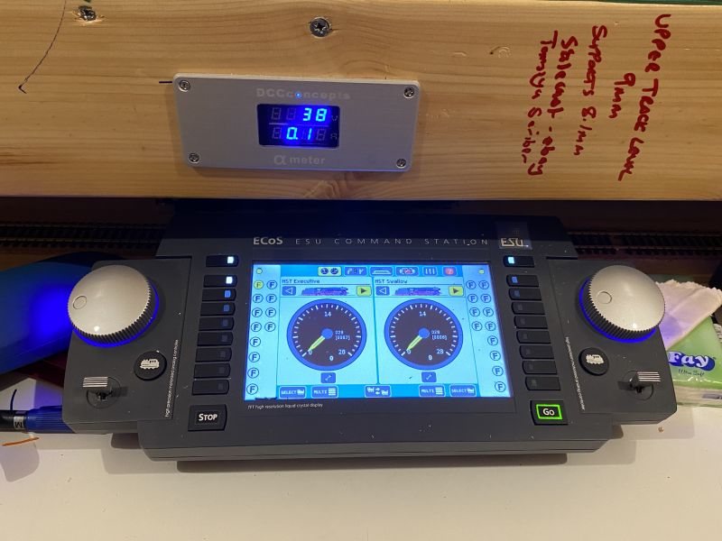
From originally whilst getting track working using DC, I've now fully moved to the ECOS and DCC
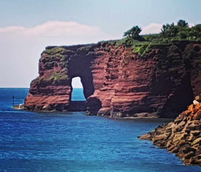
The front section lower will be a coastal town (arcades, restaurants, pubs etc) with the mainlines running through on a sea wall - much inspired by Dawlish.
Not sure what will be behind the upper main yet. Likely it will be B&B / hotels but I haven't ruled out the back end of the town football stadium!
The coast will run at the front of this section, round into the "bay" area. I'd like to make the cornerwork of cliffs section be similar to the one in Dawlish -
To the right will be more scenic and VERY much inspired by Chris's Teasel Bay.
The lines will come out of the tunnel straight into a more semi rural style coastal station with sea wall. Yep that's right - I'm a gluten for punishment with two stations on the layout lol!
I've bought a base for the station I like off ebay. A nice kit that I saw used on the beautiful Moldy Rapsberry Yorkshire Dales layout. (Strongly recommend a visit if you've never looked)
Although unlike Teasel I won't be adding any magnarail (doing this so far has made me realise my skill limits lol) I plan on having this as an active tourist area, straight from station to promenade where they'll be stalls, amusement arcade and hopefully a helta-skelter on the beach itself for kids!
The beach will lead into cliffs around where the lines start curing out to the right. (where the Copydex is!!)
The incline at the coastal end will merge to the mainlines as will the second incline/decent.
Underneath the section is the hidden loop and sidings.
Because I won't get access to this easily, the sidings have sensors at each end which will let me know if trains venture too far and get too close to the points interfering with trains on the loop line.
To get these out of the way, the points on this side are the first I've motorised using Seeps. - Which were god awful to align on my own and I can't begin to say how many times I've banged my head going from under to above the boards!! Glad thats over!
The siding also has it's own independent power so once a train is stored (like the APT-E) I can turn power off and not have the train running idle with all its lights on.
I've reserved space on the control panel for installation of this switch and switches for other lines I can drop power if required to other areas inc bay platform and parcels platform at the main station. Not that I guess it's massively needed but given I worked out how to do it, it's nice to have the facility!
Using a bridge rectifier with LED's I can easily see if power is on or off on the control panel.
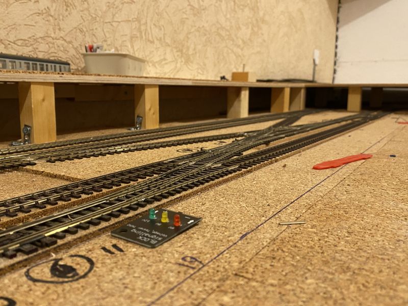
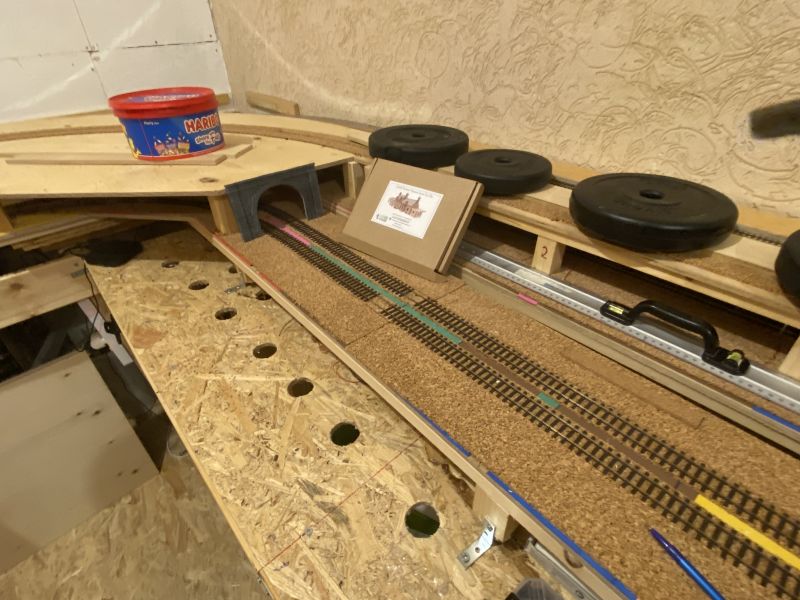
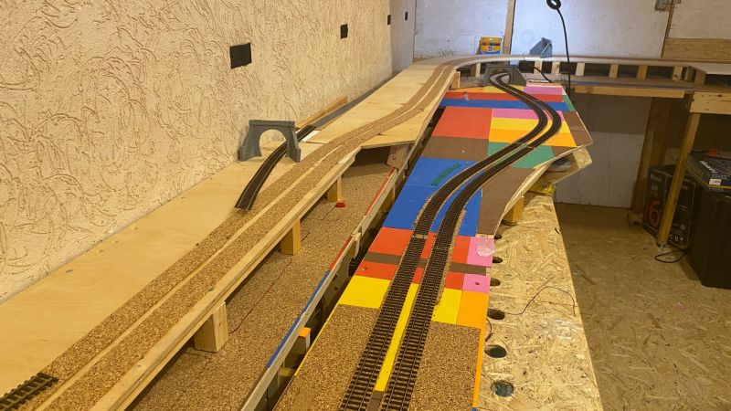
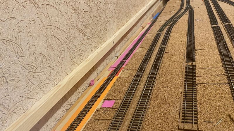
Once the two lower lines pass the signal box and bend off, this whole area will be very much scenic.
That part of the track is my favourite so far.
I added DIY super elevation and although only slight, it does make it look better. I can't wait to see how that bit looks when it's all scenic. Trains look really good weaving though this section.
The application of the DIY SE wasn't without difficulty so for the bends on the faster upper loops, I've bought 3D printed ready to go kits from West Hill Wagon Works.
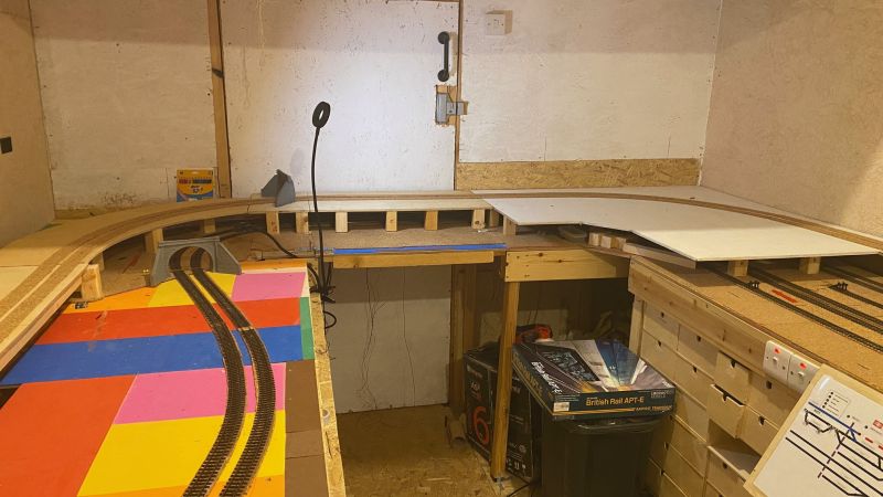
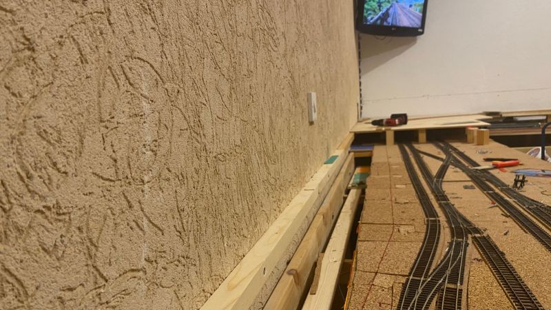
The last section towards the lift up section still needs to be secured but the "upper part of the lift out is well on it's way.
I've added a couple of points to the lift up since last posting. I'd not provisioned trains coming down from the top level to move into the station area! With the way it was, they'd just go straight into the storage area!
Whilst we are here….
I am noticing a difficulty in the lift up board lately.
We've just started to get heavy rains in Cyprus and the moisture is expanding the boards slightly. Its VERY snug now when lowered - as is the main door!
I don't want to sand anything away as this will cause problems when it warms up again in April time.
Another thing to keep my eye on though!
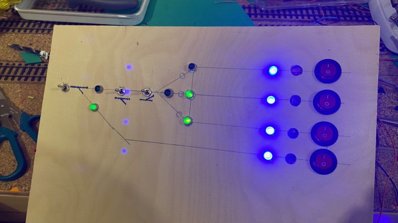
As mentioned above, I've started work on a temporary control panel.
Using ply this will do for now. It's not great, laminated and printed at work but whilst still constructing, it's good enough.
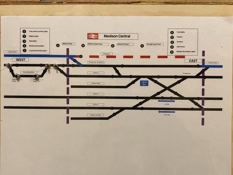
This is the only part finished and working - The hidden sections on the far West side of the layout.
The rest of the points are still in the open so will be hand of god driven for now until I build up enough motivation to work on the seeps again
Quick comment on the seeps - I soldered the connections on the boards to colour coded jumper wire then to "choc blocks" allowing for easier connection of cables under the boards. My soldering is coming on but still clearly good enough to be able to do on my back in cramped conditions!! Every little helps!
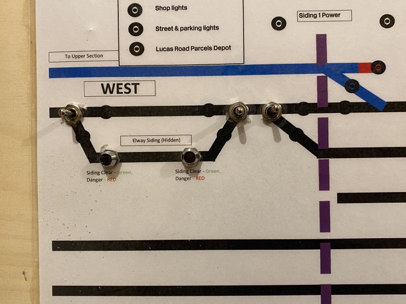
I was going to use signal position boards from heathcote electronics to show point positions but with help from the depths of you tube, I've worked out a way of getting LED's to show the active route using the feed from the frog on the seep.
A LOT more cabling but hey ho.
Whenever I put my mind to anything, I do like delving into it's history.
I lived in Germany for a long time so loved delving into the Ruhr Valley Dam (Dambusters) history and even popped to Poland and visited the site of Stalag Luft III - "The Great Escape"
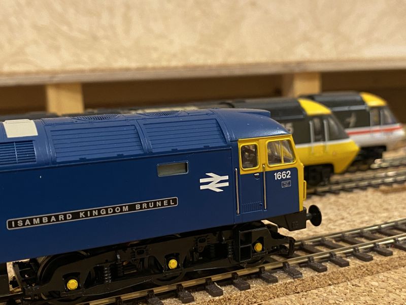
With researching a lot to do with Dawlish I watched a lot on Isambard Kingdom Brunel and loved learning everything I could about him and the work on the railways in that era. What a fantastic brain he had.
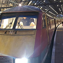
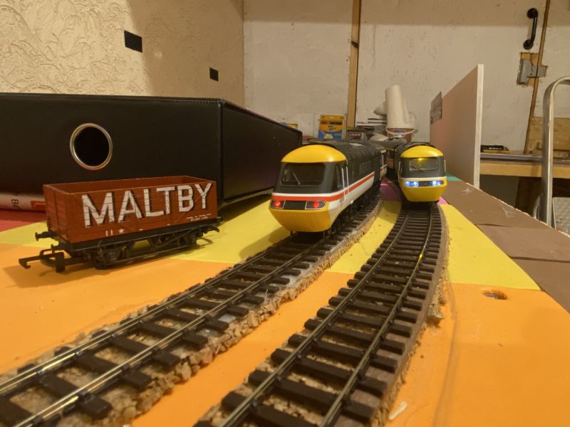
At the same time, Bachmann released a Class 47 Green Isambard Kingdom Brunel loco and although looking stunning, it's really not the period I'm after so having a good look round, I did find a brand new BR blue version of the loco that Bachmann did for ModelZone.
Early birthday present from my wife, it's on the layout and looks great!
Spent an evening running it in along side two HST's… nice to finally be able to play trains in some capacity!
I've recently managed to get over to the UK so managed to finally pick up my APT and APT-E packs along with a load of newly released Speedlink wagons.
Plenty to keep me going!
Hopefully you've stayed on through this! I hope not to leave it six months till my next update!
Be nice to have the upper section ready for track to be glued down by the end of the year, fingers crossed!
Last edit: by 1867Adelphi
One day I'll settle on a trackplan….
but likelihood is it won't be today!
but likelihood is it won't be today!
Posted

Full Member
You can't call this 'slow progress'. I am very impressed and look forward to your next instalment.
Cheers,
Claus
www.flickr.com/photos/ellef/
Claus
www.flickr.com/photos/ellef/
Posted
Full Member
Nice to see how it'll look.
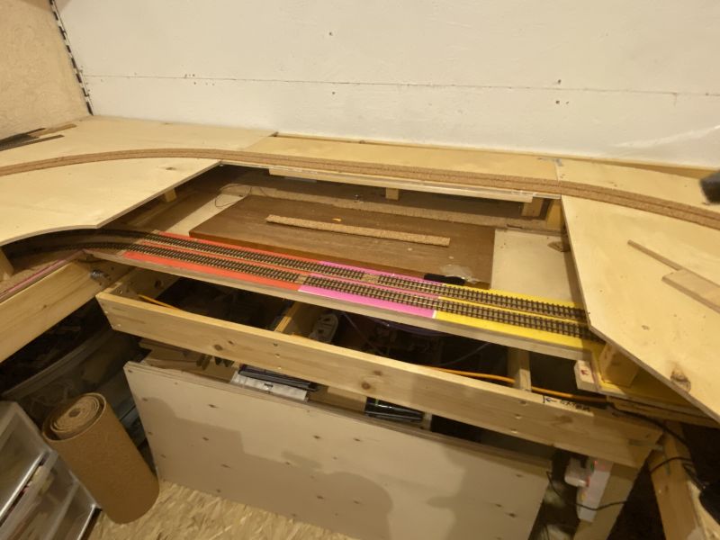
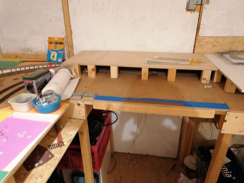
However… it's not secure yet as it's now time to take it up to make the change to the storage plan!
So this is how it currently is with the left hand track rearing round and was going to decend to a lower storage are.
That bit will change but I also need to add a couple of new points to make things work better allowing trains to come off that left hand track and back into the station area
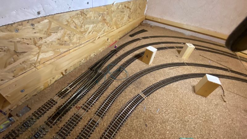
Next up will be laying a new board to replace the cut out section which was heading down.
So with the track lifted, I've made note of how much room I'll have for the storage once I get it covered.
Getting a bit late for the mini circular saw so will cut out and get the boards up next.
One day I'll settle on a trackplan….
but likelihood is it won't be today!
but likelihood is it won't be today!
Posted
Full Member
So a sort of productive month…. and then the usual loads of steps back!
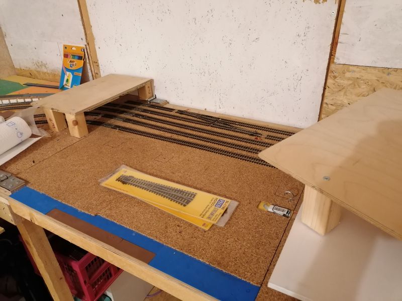
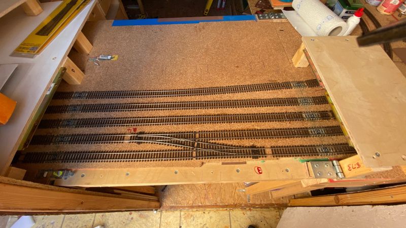
I replaced the declining board at the rear of the station and laid new track splitting off with a single point and then a 3 way giving me 4 long storage tracks.
Electrics and the points worked fine and I worked out a solution of getting LED light indicators working with the SEEP motors still using the switching for frog polarity but without need for any additional circuit boards.
All the videos I'd seen showed people with seeps using frog juicers for the polarity and the seep for the led's or frog powered from the seep and then additional mimic circuits or point indicators from Heathcotes to run lights.
Budget is non existant at the min so I was happy to get this done with no additional purchases.
I added a second wire from the frog connection on the seep to the LEDs to sustain power. (without this the momentary switches would just quickly light and then extinguish)
Basically two LED's side by side. Positive from the first LED to positive DCC power. Negative from the second to negative DCC power.
The negative of the first LED is then joined to the positive of the second and both those joined wires then connect to the output from the point motors frog!
It worked so that's all that matters lol!
I made each lane of storage have it's own power switch so I could isolate when not using and everything looked good… then I inspected my work!
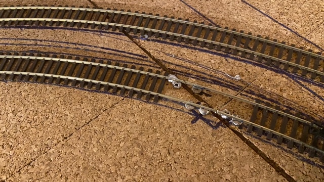
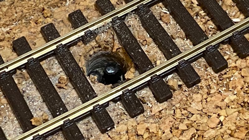
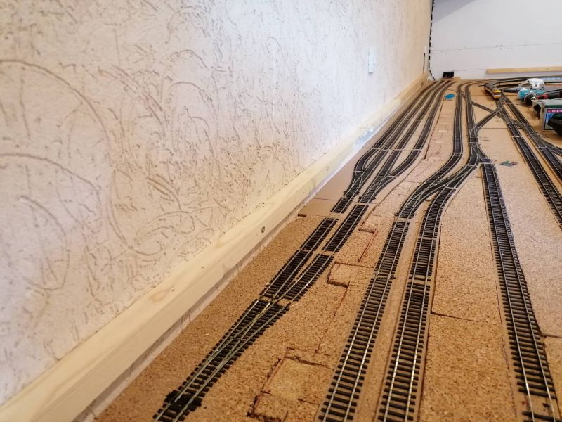
The previous day, I'd started to run out of Copydex to glue the flexitrack down so instead of waiting a couple of days for the new bottles to arrive on island… I used some spare PVA wood glue at hand.
I assume at this point, those of you who know are cringing. I didn't know… and I still don't know "why" but after painting the glue onto the cork bed, laying the track, straightening then laying ply on top then weights to hold it down, leaving to dry…. I returned to find totally and utterly corroded brand new peco track!!
Proper naive and I still don't know (I don't want to at this point) but something in the wood glue clearly did awful things to the rails… very quickly!
Absolutely gutted! But, lessons learned - stick to copydex to glue track lol!
You wouldn't think that was fresh out of the box 5 hours earlier!!!
Even with their own drop leads, the tracks just don't work. Trains won't freely move.
I cleaned the tops and it improved somewhat but considering this whole section will be covered, I can't risk leaving it so it's all got to come up and start again!
I've ordered more track from Hattons and it'll be on island on the 4th.
This was boxing day and I planned on going back in the shed and disconnecting everything and lifting the damaged track but then my world stopped for a bit.
Our border collie Elway, 13 years to the day we brought him home, slipped on a walk. By the end of the evening he couldn't stand and unfortunately he made the trip over the rainbow bridge.
Seeing as he was my companion in the shed, obediently not getting offended to my continual "ffs's" I just can't face going back in at the minute.
Not sure when I'll go back and fix my storage section. My resolution is to complete trackwork by the middle of next year so I hope it won't be long but what with wrecking a box of code 100 track and then this, my mojo has just totally gone at the minute.
Not a great end to the year but I hope to all that read this you've had a better Christmas break and I wish you all a wonderful 2023.
All the best guys.
See you next year!
One day I'll settle on a trackplan….
but likelihood is it won't be today!
but likelihood is it won't be today!
Posted

Site staff
I have glued track with PVA - just a row of it down the middle & no problems with dis-colouring of rail. Once ballasted, the track really stays where it was put.
Ron
NCE DCC ; 00 scale UK outline.
NCE DCC ; 00 scale UK outline.
Posted
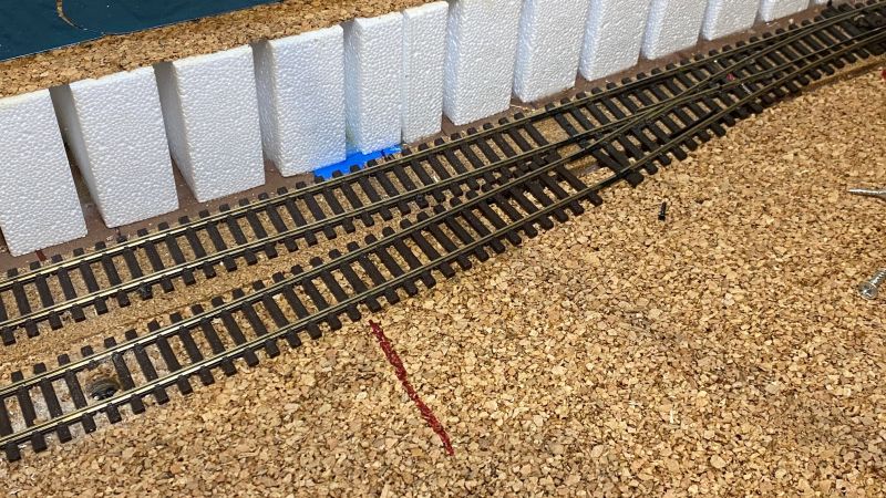
Full Member
It's quite amusing to see where I ran out of copydex (and rails are all gleaming and pristine) to where the next section is held down by wood glue and the rails look decades old!
I'll cut out all the bad stuff today and re-lay when my order gets out here on Wednesday.
One day I'll settle on a trackplan….
but likelihood is it won't be today!
but likelihood is it won't be today!
Posted
Full Member
I reworked the control panel to a more longer term one. Not a final cut but enough to keep me going for now.
All the points that will be hidden or hard to get through have now been wired up.
I've really had enough of point work so for now, I'll manually switch the rest as I need to move on to scenics.
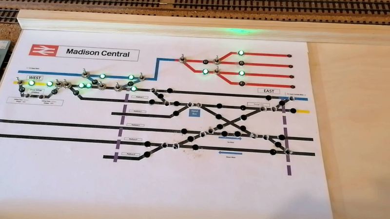
The method for the control panel lights utilising the polarity of the point frog works so I'll continue to use it.
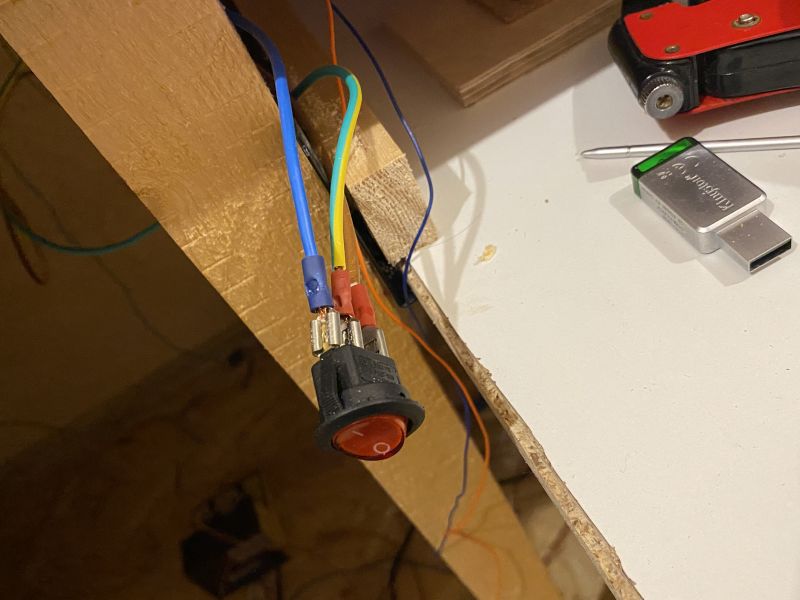
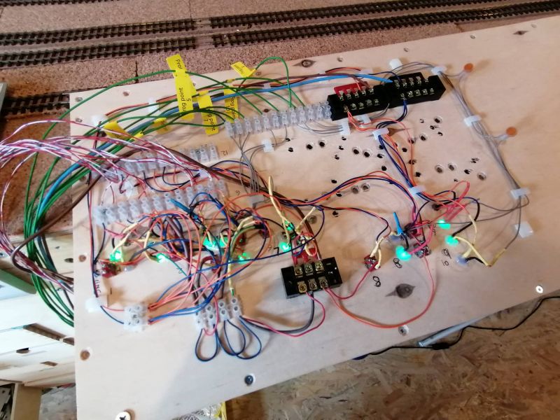
I've used some left over Krone blocks from work. 3 feeds from each point (2 switch feeds and the frog) are punched into the top. Then dropper wire is then used to take it up to the panel.
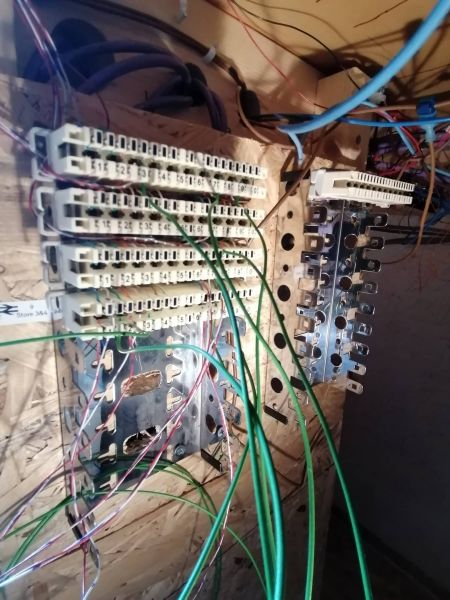
Here's a picture of the underside of the panel. The green wires are feeds from the frogs for LED's, the red and white wire is for point switch control.
As said before, I need pos and neg track feeds for the LED's so there's terminal blocks for that.
I've tidied it up (believe it or not!) and that will do for now. I've drilled holes for the other switches and LED's but i'll do that when I've rediscovered mojo for this project!
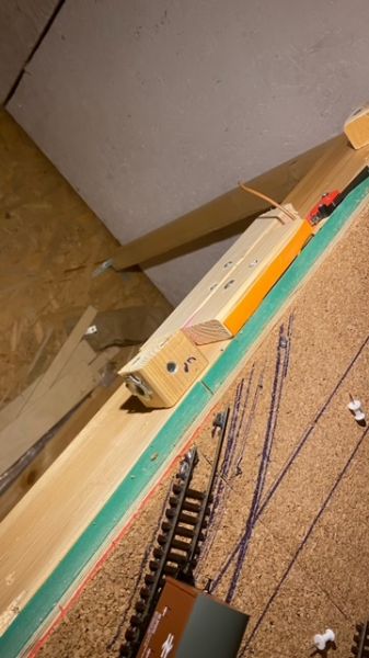
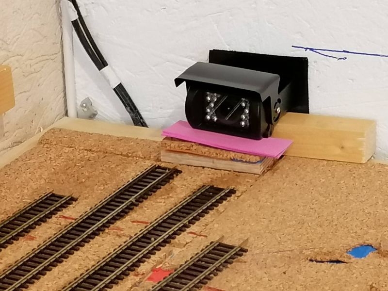
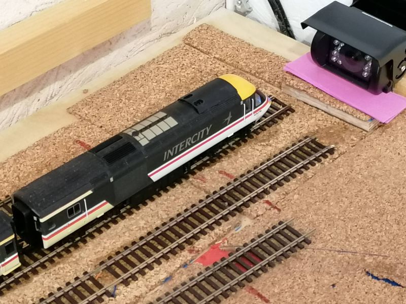
Before finishing this section. I needed to get eyes on the storage yard when it's covered with scenics.
I bought a truck "park camera" from ebay and set it up.
Finally, something that worked straight away and perfectly does what I need it to do.
Camera added at the far end
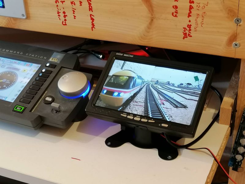
Train moves into one of the four storage lanes
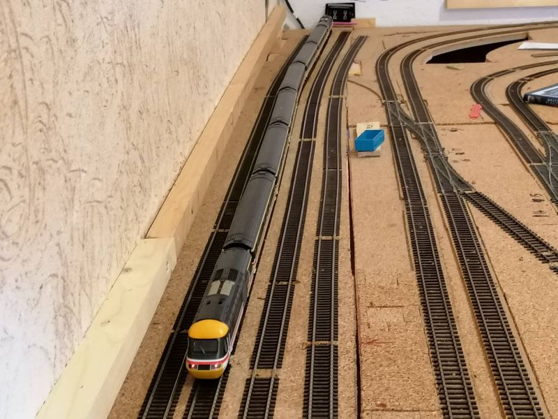
And from the controller desk, I can see how much track I have left for the train to occupy.
After a recent trip to the UK to visit my mum, I didn't survive a trip to Rails of Sheffield without the wallet bending.
I picked up a rolling road from DCC Concepts and a really well priced Class 58 EFE rails loco.
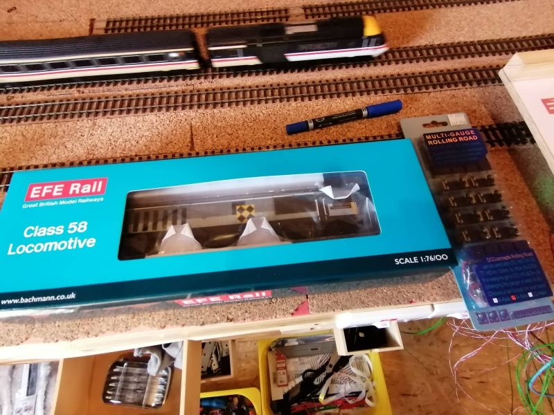
The loco runs beautifully. Its got a lot of weight and eventually I plan it to pull a long rake of coal hoppers.
Although "simplistic", getting the body off the chassis to fit the decoder was a bit of a phaff. Despite running so, so smoothly, I've noticed the running lights are not illuminating so a bit of work needed there.
From being a newbie to the hobby, I am quite frustrated that not much runs perfectly out of the box. There always seems to be a tweak needed beit CV or try a different decoder to fix issues.
So, finally near to getting on with the fun stuff.
There will be a town area to hiding the upper section as it passes over the station. As such, I'm going to sort station platforms first to get it out of the way, then I think the plan will be to move away from the station side and attempt to play with what will be the coastal beach area. To prepare I've been re-reading Chris's Teasel Bay thread for inspiration and motivation.
I was going to go straight into trackwork for the upper section but I think after so long getting the lower section track finished - I need to do something to get my interest and enthusiasm back first!
One day I'll settle on a trackplan….
but likelihood is it won't be today!
but likelihood is it won't be today!
1 guest and 0 members have just viewed this.