Colin's Work Bench
Posted

Full Member
The small one-off jobs behind the scenes
****************** FYI This Topic now has an index at the top of Page 1 Post #1 *******************************British Finescale Kits - B7 Single Slip
Much excitement around these parts, and relief, when this kit arrived in the mail in record time from the UK.
The single slip has a crucial and central position in the Upper Hembury track-plan and so proceedings have been on hold until this latest addition to the British Finescale Code 75 OO Bullhead range became available. A quick check confirmed that the base structure fitted perfectly to my Templot plan (✔ï¸) and now on to the build.
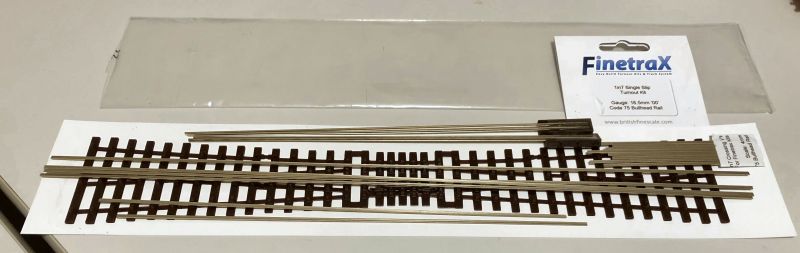
This component comes in at 345mm, almost 100mm longer than the Corresponding PECO Bullhead product, thanks to the much shallower exit angle resulting from the B7 geometry of the kit. Now all that remains is to get it up and going!
 Last edit: by Colin W

Posted
Full Member
This build was straightforward, having had the experience of assembling single turnouts but took me around 3 hours in total of "hands on" time.
I counted 23 individual rail pieces, each of which must be accurately measured out, cut and trimmed to fit. Then there are a fair number of wiring connections to be made once all is together. There is a detailed step by step guide which makes the whole process run smoothly. The end result is a delight when you get there.

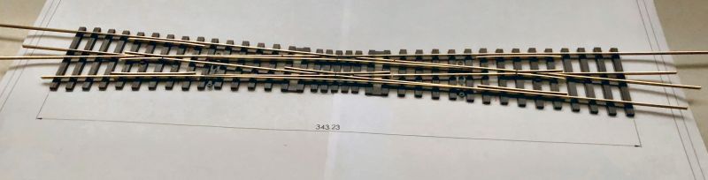
Another positive I discovered of using the kit is that the over-length rails which are supplied can used to advantage. I had a 58mm gap between the Goods Yard exit of the slip and the next turnout. I divided this by two adding 3 sleepers and 29mm to the exit lane and will do the same to the turnout approach. Hence I totally avoid the need for short and hard to fit track length between the two by bridging with turnout lane extensions.
Nice one, and a technique I can use to advantage in several other installs on Upper Hembury!
Last edit: by Colin W
Posted
Full Member
Cheers Pete.
Posted
Full Member
I've two locations where these are needed on the track plan, most importantly protecting the main line from traffic coming from the tannery. Traffic through the trap will be controlled by a ground signal. It occurred to me that the Finetrax sleeper base which comes as two joined halves would provide a convenient starting place to build a working single rail trap (as per GWR practice).
A sacrificial half template and a left switch blade / tie bar were combined with the required running rails to give me this.
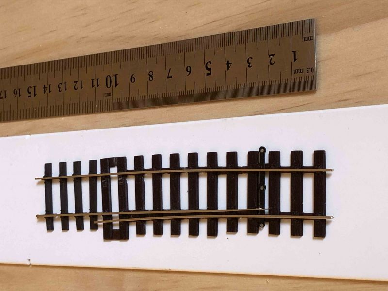
Curved to fit the profile of the approach from the tannery to the single slip ahead. Note with only one switch blade and no point motor the blade tip is sitting more to the right than it will after installation.
A work of caution: I had a cunning plan to make the unit extend further than shown here by using rail extracted from PECO Bullhead track. However, the sleeper chairs of the template must be microns too tight to accept the rail. Bullhead supplied by British Finescale of course presents no problems.
Posted
Full Member
Cheers Pete.
Posted
Full Member
Two adjacent sleepers are jointed (below ballast level) at the edges so leaving no supports directly under the rails. This allows for connection wiring to be soldered onto the rails where this is needed to ensure connectivity between switch blades and their stock rails.
When laid, the connecting strips will be buried below ballast. I can take a photo from beneath on a kit I've built and wired up and will post it later.
Posted
Full Member
Cheers Pete.
Posted
Full Member
Just to advise that I've reworked post #10 (p1) on my CDU as I decided the original diagrams and description were totally undecipherable to me after 7 months. Must have been written after a very good glass (or 2) of something or other.
Hopefully the new version will make more sense, you guys were far to kind letting me get away with that one.
:Red Card :It's a no no
Posted
Full Member
I bet you haven't reworked as many post's as me! Hang on, I have some editing to do. :)CDU Solenoid Control - update
Just to advise that I've reworked post #10 (p1) on my CDU as I decided the original diagrams and description were totally undecipherable to me after 7 months. Must have been written after a very good glass (or 2) of something or other.
Hopefully the new version will make more sense, you guys were far to kind letting me get away with that one.
:Red Card :It's a no no
Cheers Pete.
1 guest and 0 members have just viewed this.