Colin's Work Bench
Posted

Full Member
The small one-off jobs behind the scenes
I too, in the main, use Zimo decoders Colin and yes, I love that braking function now available on the more recfent chips (or indeed, one can re-programme the older ones to include it).I'm impressed with how your Prairie responds to "normal" decoder settings - I think I ought to get on with some track and wheel cleaning……………. :thumbs
I also need to get some practice in on small scale soldering etc. :hmm
'Petermac

Posted

Full Member
SR A1X TERRIER #2662 - DCC Sound and Stay Alive - Part 1
Back in posts #6 and 7 I installed basic DCC + Stay Alive into the 2019 Hornby Terrier. Now with Upper Hembury edging nearer to reality I've bitten the bullet and opted to put sound into this model.
If that seems a waste of a good DCC install it was not because I have a second version of this lovely model, viz. SR No10 "Cowes". A simple chassis swap-over gave Cowes a long awaited DCC setup and me a free chassis for #2662 sound!
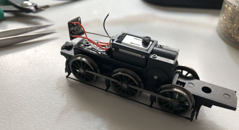
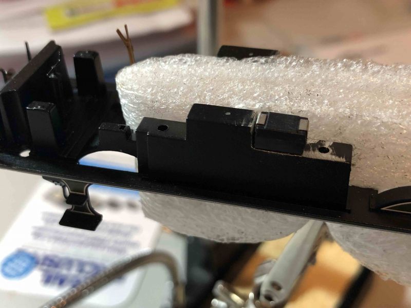
Going back to my regular source of these sound packages, viz. Youchoos, I found there was an excellent variant of their install guide which allows for addition of modest Stay Alive capacitors. They note there is no room behind the engine and as the first two photos show very little forward either.
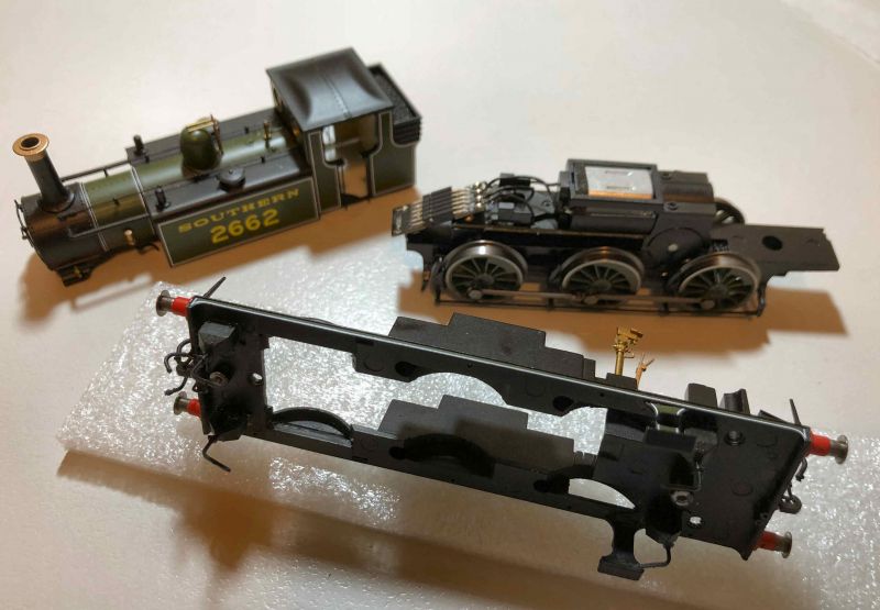
The model comes apart into three sections (if you're lucky #). The chassis is held in by just 2 screws (short Conical Head at front, longer at rear) but the upper and lower body sections are held by seven, four of them well concealed.
As before the 6 pin socket and its mounting plate were removed to reveal the modest free space available for Processor and speaker.

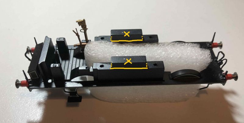
This leaves no room for any stay alive at all but that is where the Youchoos cunning plan comes in. The following photo shows the lower section of the Body with the required cuts. This frees up just enough to fit 4 tiny Tantalum Capacitors atop the truncated side tank interiors.
Regarding the installation, I'll continue in Part 2.
# I tried first with No10 "Cowes" as I had the chassis out at the time but I found that even after removing all seven screws the back section of the two halves remained firmly attached. I suspect that overzealous application of CA has locked these sections and am grateful all went OK on 2662
 Last edit: by Colin W
Posted
Full Member
I'm following in earnest - eagerly awaiting Part 2 ……… :cheers
'Petermac
Posted
Full Member
Excellent advice, thank youHi Peter,
I know what you mean. Assuming you have a suitable small iron, try practicing on an old piece of circuit board from something redundant.
Typically I pull anything electronic apart once it fails for potential "opportunities in search of a need", odd diodes etc.
Try this technique:
Find a board with some very fine electronics, snip off a small component topside and excess wire if any beneath and practice soldering a spare DCC chip wire to the residual solder spot on the reverse.
Tin the trimmed wire first, then with iron not too hot, apply heat to the wire, not the solder point. Offer the wire still being heated to the spot and it should mate directly. This way you avoid direct heat on the DCC chip. You can have a short piece of fine heat shrink on the wire to pull up, if the bare section gives you concern.
Even if your test join is larger than your DCC, this way you'll get the idea and feel for the technique.
Clive
"Probably quite loco…"
"Probably quite loco…"
Posted
Full Member
My plan for this install was determined by the availability of suitable chips for the small space and desire for a Stay alive (SA)
ZIMO are moving on to a new generation of Sound Chips. I had various options but the prospect of superior sound quality (16 bit), a smaller footprint and on board SA control (for up to 1000uF) caused me to favour new over old. In fact the higher cost was offset by avoiding the need for external SA control circuitry.
Unfortunately the chip I wanted was the MS500 wired version but this remains "availability - SOON!" so I settled on a 6 pin version. Having just removed the supplied and totally unsuitable 6 pin socket in the Terrier I needed a solution.
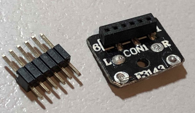
By good fortune I happened to have an old 6 pin socket (out of the Bachmann Collett Goods if I recall correctly), which can be vertically orientated for a horizontal mounted chip. It is shown here combined with a 6 pin insert stripped from an unwanted 6 pin harness (my motto: never throw anything potentially useful) This proved helpful for continuity testing my cut down device.
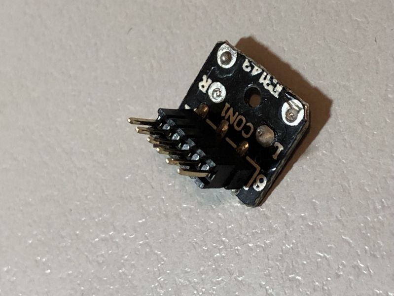
The PCB board was trimmed back to make the required height and the mounting socket glued in place after I succeeded in braking one tiny internal connection during testing and had the delicate task of repair and reassembly!
Aside from the tidier install, the reason for favoring the "make do" socket over direct soldering leads to the pins is that it is very easy to un-solder a pin from the chip during the process.
The socket then fits neatly at the front (to be glued in place) with plenty of room for the short DCC chip between it and the motor.
TBC
Last edit: by Colin W
Posted
Full Member
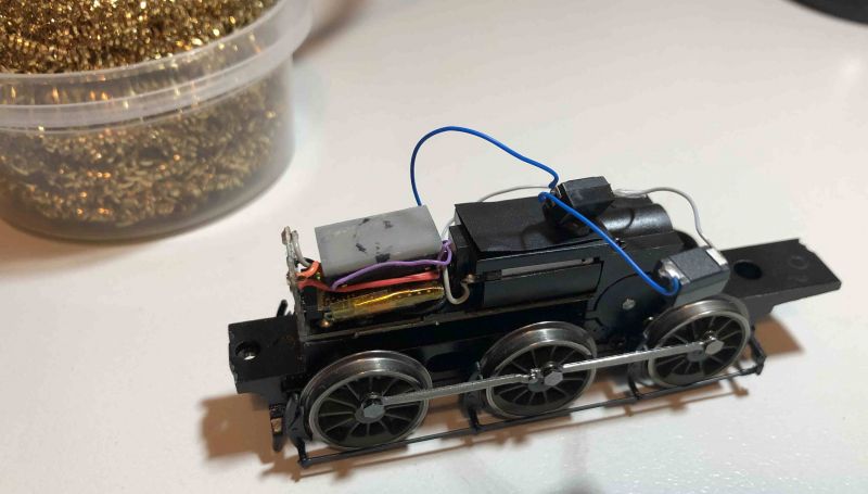
Assembly from here was straighforward. The four wires were installed onto the socket PCB so they could all sit above the DCC Chip.

The chip fits snugly
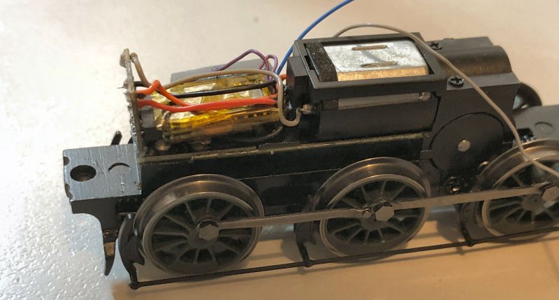
With the tiny Minnow 4 speaker on top, just fitting.
This sits up slightly at present but has scope to compress the wires down by up to 2mm to fit in the boiler space. Only the Stay Alives remaining to be added before reassembly but a quick running trial showed that everything works.
Posted
Full Member
I always keep bits and bobs for future use.
Thank you for sharing.
Clive
Clive
"Probably quite loco…"
"Probably quite loco…"
Posted

Full Member
Do you know if the non sound Zimos are about to upgraded? Built in SA circuitry would be very convenient.
Posted
Full Member
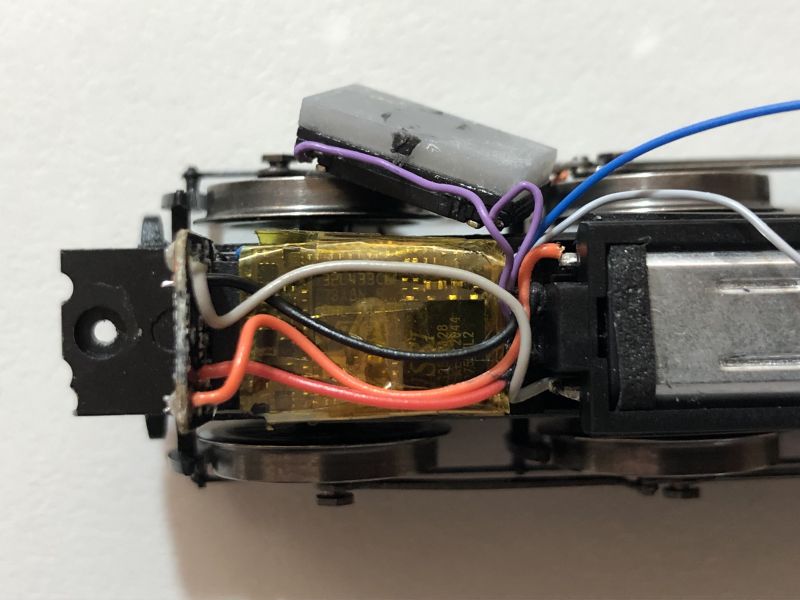
The final steps were relatively straightforward with one minor change as I was sent 470uF rather than 220uF capacitors so only needed 2 for this install. This reduced the space needing to be cut from the metal bodywork. The cut on one side is shown here with the Tantalum cap sitting in the gap I'd created.
The two Caps were wired directly to the MS500N leads
and one cap fitted snugly into the recess in the side tanks each side.

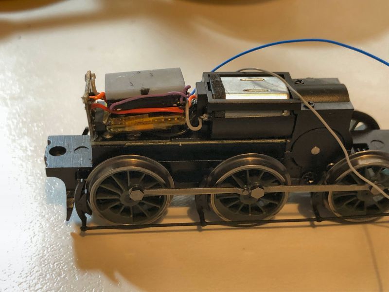
It turned out better not to have the 6 pin socket PCB glued down because once the DCC chip plus leads and caps were installed into it, it was better left free to bed down on installation. It naturally settled into the ideal position at the front avoiding binding during assembly. I think I'd built up quite a wad of thick CA when fixing and this caused the PCB to sit a mm too high!
Continued below………
Last edit: by Colin W
Posted
Full Member
Regarding John's question on ZIMO stay alive On Board control, this appears to be restricted to the new generation sound chips based on their promotional comments.
I'm less familiar with their non sound offerings but there were many in the list, some may well be new. The prices too were "new", they made my eyes water TBH so I'm glad I'm ahead of the curve with all my hardware purchases :cool:
Last edit: by Colin W
Posted
Full Member
Regarding the factory added stay alive from Zimo, I've just installed their MX 644C with one into my new Oxford Rail Class 27.
Youchoos do an install guide for this decoder which requires cutting a hole in the coal load to accomodate it - it's cylindrical and much bigger than the small tantalum. It does work although only provides about a second of power when lifting the loco from the track. I have a few locos with "super caps" installed which run without supplied power for almost the full length of Don Mclean's "American Pie" ……… :hmm

'Petermac
Posted
Full Member
Thanks Colin. I was hoping John Gymer at Youchoos may have given you some advance information. The site isnt particularly informative - all the "economy" options that I use are "temporarily out of stock" which is rather unusual. Although I see they have all just had a 20% price increase :shock:. Fortunately, like you, I topped up my reserve stock in January at the old prices.Regarding John's question on ZIMO stay alive On Board control, this appears to be restricted to the new generation sound chips based on their promotional comments.
I'm less familiar with their non sound offerings but there were many in the list, some may well be new. The prices too were "new", they made my eyes water TBH so I'm glad I'm ahead of the curve with all my hardware purchases :cool:
Posted
Full Member
Hi Peter,Oh how I wish I could manage that sort of thing Colin …….. :) I admit to being far too ham-fisted - as I've said previously, I'm much better with a lump hammer than I am with a scalpel !
Regarding the factory added stay alive from Zimo, I've just installed their MX 644C with one into my new Oxford Rail Class 27.
Youchoos do an install guide for this decoder which requires cutting a hole in the coal load to accomodate it - it's cylindrical and much bigger than the small tantalum. It does work although only provides about a second of power when lifting the loco from the track. I have a few locos with "super caps" installed which run without supplied power for almost the full length of Don Mclean's "American Pie" ……… :hmm
thx for the feedback.
Regarding your J27 install I took a peek at the LNER section in Youchoos and was confronted with an Alphabet Soup selection of models I'd never heard off. What a reclusive world I'm inhabiting with just GREEN GWR and the occasional SR loco on the horizon.
The J27 reminds me of the Collett Goods so I can imagine the tender size you have available, mostly taken up with the OR 21 pin socket on its PCB. A huge change from the GWR Collett; you saw the size of the 6 pin PCB that had, I used it in the Terrier! This latest is a monster PCB and it has a small on board electrolytic capacitor for some reason. I had a quick look but couldn't find anything relevant as to "why?" over in "The Other Place"
I noted that the Youchoos install retained the direct wired 25V 1000uF electrolytic capacitor which came with the MX644 chip. It is worth commenting that there'd be little advantage switching to tantalums to avoid cutting the model. The direct wired (up to 1000uF) Stay Alive can fully utilise a 25V Capacitor while the other option using a Stay Alive controller gives only 16V which, uF size for size, stores only 64% as much charge. So you'd need 4 * 440 uF tantalums at 16V to better the storage as supplied, but at a substantial additional cost penalty of dearer caps and a SA control chip.
For anyone going down a similar path there are a couple of traps here that are essential to note regarding Zimo direct wired Capacitors to the Chip = "Energy Storage Support" in ZIMO speak and using Tantalums
1) The voltage of direct "Energy Storage Support" varies by chip. If using this feature, cross check the supplied voltage with the ZIMO website. Peter's MX644 supplies 25V which is too high for Tantalums (rated at 16V). Many others like my MS500 have 16V direct hence I can use Tantalums
2) Always check your Capacitor specifications. I narrowly escaped a problem when I found I had been supplied 470uF not 220uF Caps. They are black, very hard to read easily and almost the same size. I could have easily overloaded my chip by wiring in the four I thought I needed
Tantalum capacitors provide a great solution when you have very limited space and require the low level SA support which every sound install should have to avoid project resets.
Posted
Full Member
John,Thanks Colin. I was hoping John Gymer at Youchoos may have given you some advance information. The site isnt particularly informative - all the "economy" options that I use are "temporarily out of stock" which is rather unusual. Although I see they have all just had a 20% price increase :shock:. Fortunately, like you, I topped up my reserve stock in January at the old prices.
The ZIMO site lists the various specs by chip.
ZIMO Specs
See the line item "Energy Storage Support", it also has a (+) drop down window with more info on this item. That should answer your query.
Posted
Full Member
I've a period ahead of me where I'll be between layouts so to speak; Weston-Heathfield being retained until the Sydney grandchildren have visited in June and July plus Upper Hembury moving slowly forward.
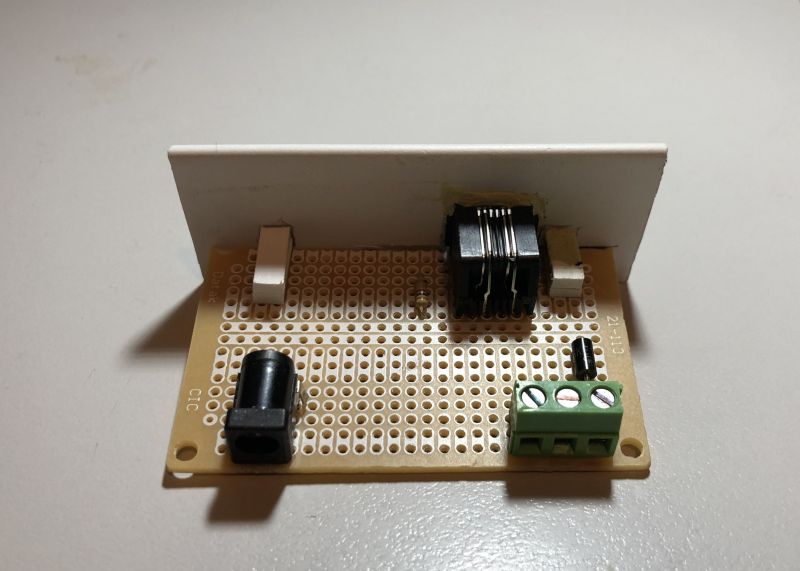
This means I need my PowerCab to connect to either setting and to do that I need two interfaces. This controller has its own idiosyncratic setup with the handset using a flat 6-wire cable and RJ12 plug. The interface, essentially passive, allows power connections in and DCC output to track.
For a simple socket board, this item is not cheap as a retail version so I figured I could knock one together. Most of the parts I had to hand, the only purchase needed was a TVS Diode (Bi-directional) which is wired across the output lines as protection against a voltage surge and a small prototype Board, total cost $4.20.
The product is nothing flash but it works
Posted
Full Member
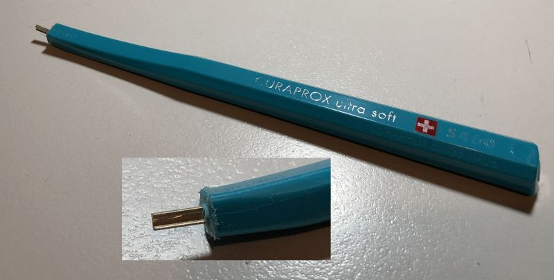
Not a new idea, simply my version of a clever tool which I've seen before here on YMRC but can't find right now. Full credit to the unknown designer of this great device, imitation is after all …
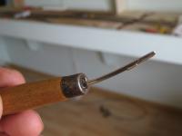
I'll soon be needing to tackle Code 75 Bullhead track joining (hopes!) and an old toothbrush gave me an idea for a handle of practical design. It is made of a hi-tech material which would hold the track section tight due to its toughness and slight flexibility.
A slightly undersized hole was drilled in the cut off end and a short length of Bullhead, previously sharpened to a chisel edge was pushed in firmly. It isn't coming out any time soon!
Posted

Site staff
Ron
NCE DCC ; 00 scale UK outline.
NCE DCC ; 00 scale UK outline.
Posted
Full Member
After the recent running session, I noticed that my usually reliable 6011 King James I was drawing rather more current than usual. One feature of the NCE PowerCab is the instantaneous current reading and this had crept up to around an erratic 200-250mA with only a moderate load. It wasn't struggling but that did seem a concerning matter.
Thanks to some very helpful advise from Jeff (SRMan) I set about pulling the loco apart in search of issues. I've been following Hornby lubrication recommendations on a regular basis and all appeared fine with the axles once I slipped the keeper plate off.
Pulling the body shell off revealed two possible issues. As I'd never done this before in its 5 or so years the problem clearly goes back to the original assembly because the motor had a wire partly trapped under it and hence the worm gear didn't seat properly down in position on the gear train.
Also the top gears appeared to have a thick grease so this was stripped away as best possible. The gear train is fully enclosed and short of full disassembly I had to remove what I could from the exterior. With a good quality gear lube applied and the motor aligned accurately, I have the loco running at ST 50 drawing a more typical and steady 90mA.
This experience makes a case for installing an in-line ammeter as an early warning of operating difficulties if your controller doesn't provide that useful feedback.
Last edit: by Colin W
Posted
Full Member
I've never checked any of mine but maybe I ought to do so. I tend to expect them to run straight out of the box ……
'Petermac
Posted
Full Member
Completing the CDU Modules - Part 2
Go back 6 months ago and I was rescuing my purchased CDU modules from the excesses of an over zealous postman. Details here……
Completing the CDU Modules - (part 1)
With progress made these were put aside for a suitable day. Now I've come back to properly test out the CDUs and calibrate for use with the British Finescale Code 75 turnouts which are much finer build than Code 100 devices.
I've now got the benefit of a very clever bit of kit built for me by Graham (of Traverser fame). This regulated two way power supply allows to dial up regulated voltage to 25VDC or a steady current up to 1A.
In this case I was keen to drop the operating voltage on my CDU module from the 25.5V (DC) default as supplied, which gave a massive clunk to even a standard Hornby turnout. I could see it ripping my turnouts to pieces, not the least because the switchblade travel on the finescale is just 2mm vs the 5mm on Code 100 set track which the Solenoid has to cope with.
This shows my setup.
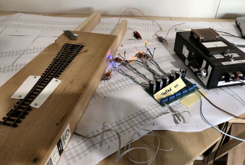
Starting from 20V the voltage was taken down progressively to 15v where it was still more than adequate to throw the switch blades. That's good as I have a 15V regulated PS rated to 4A.
The beauty of this design of CDU is that it allows for direction indication as can be seen from the orange and blue lit LEDs. The connection thru the device is always "on" when powered so one or the other LED is lit with the few mA current flowing via one solenoid coil. This also does away with the need for momentary switching.
A side benefit of the destruction wrought damage caused by the postie, I changed the individual switches over to DPDT which allows for frog switching to be done at the same time as throwing the switchblades.
Last edit: by Colin W
1 guest and 0 members have just viewed this.