Colin's Work Bench
Posted

Full Member
The small one-off jobs behind the scenes
Completing the CDU ModulesI'm now well on the way to pulling all the damaged modules' components off and rewiring to suit my control panel. This pic shows the bank of 5 CDUs each one capable of driving 1/2 turnouts as required.
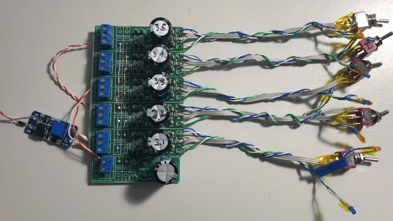
At bottom is the Reservoir Capacitior unit which acts as an energy bank to power the return leg of solenoid action.
To the left the small board takes input of 9-12V DC and generates an output of 25.5V. One useful feature, as yet untested is that this output voltage can be dialed down from the max by way of the blue potentiometer. With my lightweight Bullhead code 75 turnouts and short throw I'm hoping I can dial back the CDU output power to meet my needs.
 Last edit: by Colin W

Posted
Full Member
Note: this continues my work on these turnout kits first reported here:
https://yourmodelrailway.net/view_topic.php?id=16886&forum_id=6#p305296
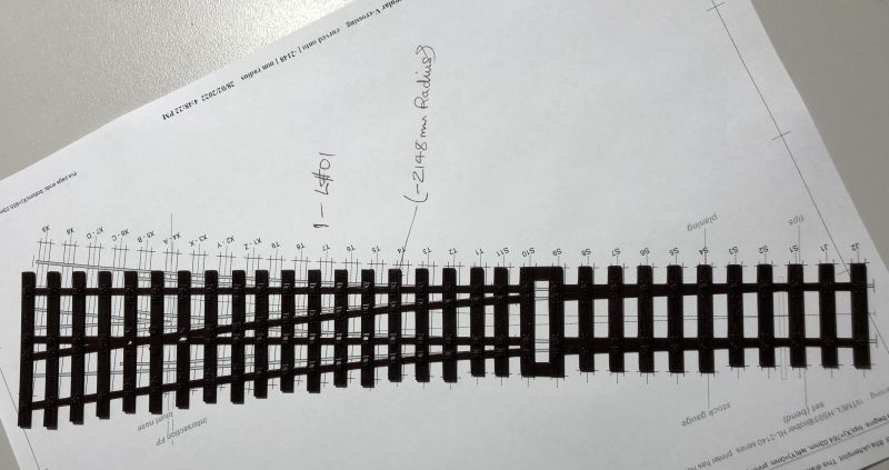
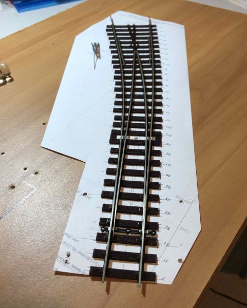
My first kit assembly for a B7 LH turnout went very well and was straightforward. Now I've moved on to a second similar kit but one requiring a significant reverse curve on the main track. These are the detailed plan and the bare sleeper moldings from the kit, first side by side and then overlaid to show the required curving
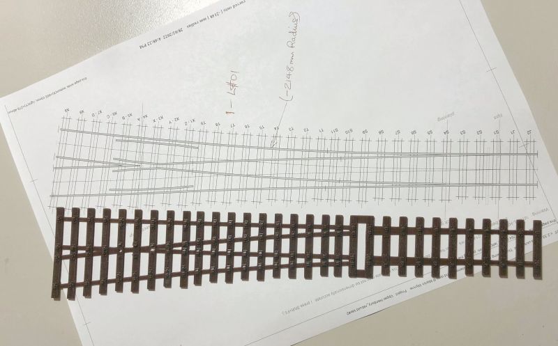
There is useful help available on how to cut the webbing to achieve the required curve, my plan is to create a template which will hold the cut base in shape while the various rails can be inserted.
Last edit: by Colin W
Posted

Full Member
Do you have to cut the sleepers and bend it to make it fit the template ? Seems odd - can't you just buy a sleeper base to match the plan ?
'Petermac
Posted
Full Member
https://www.rmweb.co.uk/community/index.php?/topic/160234-new-range-of-simple-to-assemble-00em-gauge-pointwork-kits/Can you excplain how that works Colin.
Do you have to cut the sleepers and bend it to make it fit the template ? Seems odd - can't you just buy a sleeper base to match the plan ?
has various info on this but the range of curving available from one sleeper base has huge advantage over supplying a diverse set of different moldings, each needing their own injection mold to be produced.
The base is very soft and flexible and appropriate cuts are made in the various webbing between sleepers. This is why I plan to have a pro forma template to hold the sleepers in place once the webbing is freed up. It has been done successfully and reported so I'm confident it'll be fine.
Posted
Full Member
https://www.rmweb.co.uk/community/index.php?/topic/160234-new-range-of-simple-to-assemble-00em-gauge-pointwork-kits/&do=findComment&comment=4701029
Last edit: by Colin W
Posted
Full Member
Is the web still quite strong and rigid once you've glued up all the gaps etc ?
'Petermac
Posted
Full Member
Hi Peter,Thanks Colin - I haven't seen these before but they do look like cunning bits of kit. You say you've already done a B7 point and presumably, that was successful so looking forward to seeing how you get on with this new one.
Is the web still quite strong and rigid once you've glued up all the gaps etc ?
You must have missed it at the time but I put up a topic last October when I first discovered these turnouts. see here:
https://yourmodelrailway.net/view_topic.php?id=16886&forum_id=6#p305296
There's various details about the kit structure etc and some more info on the range of curving. I also reported my first assembly but this was for the kit as supplied, uncut to give a straight B7. Once the individual rails are inserted that will confirm a lot more structural rigidity and I don't think the webbing needs to be glued but I might do anyway.
They are very easy kits to put together, even for a beginner track builder like me and look the part once completed
Last edit: by Colin W
Posted
Full Member
I have read your posts on the B7 point and also popped over to see what"s been said on Rmweb - a very interesting concept I must say so I'm now following your adventures as a linesman …… :thumbs
'Petermac
Posted
Full Member
First some calculations and measurements regarding the size of cuts and openings which were required in my webbing.
A simple pair of measurements off the Templot plans (enlarged on screen) for the B7 straight and then reverse 2148mm radius curve told me that the i.d. gap between the end two sleepers shortened by 0.1mm in the curved variant. i.e. I needed only that small gap cut out of each section of webbing on the mainline side.
This ties in well enough with the calculated shortening of the arc which is required between mid track and inside rail (viz the difference in lengths of arcs of radius 2148mm and 2139.8mm). This is is only 1.1mm in total for the entire curved section.
To hold everything steady I prepared a simple jig to fix the Switch zone and then made the recommended cuts. Once done the sleeper array easily bends to overlay the lines of the curved track.
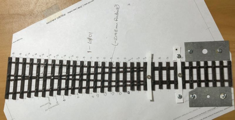
This shows it totally unfixed at the frog end. The linear displacement of the mainline to the right of straight is 18.6mm.
I'll secure the sleeper ends and mid sections before running some CA into the cuts and then adding the rails. So far, very simple.
Last edit: by Colin W
Posted
Full Member
After a quick check with the stock rails that all was in order, I dropped CA into the closed gaps and thickened CA in those opened out. Then I reinstated the stock rails to ensure all the base was held in alignment.
Stock rails are normally the last pieces of rail inserted into the template but serve a useful purpose when shaping.
Here the adjusted sides of the template are held securely down in place with some handy curved PS strip (0.8mm)

PS you might note the similarity here to a "Y" turnout.
With the B7 geometry, for a "Y" this requires radii on both sides of ~2371.5mm whereas the present sample has a somewhat greater bend in the mainline to -2148mm. Hence the geometry of my current sample requires only a modest further 2.5mm lateral deflection of the main beyond the "Y" which I've shown is clearly within the capabilities of the kit.
Last edit: by Colin W
Posted
Full Member
One of my favourite locos and one which will be heading over to Upper Hembury is 4539 - Class 45xx Small Prairie by Bachmann. I fitted this with Sound three years ago but then the ZIMO chip did some peculiar things a year ago and it went back to Youchoos.
It was a long torturous path to getting a replacement. Back in post #9 last Sept. I described installing it with a new smaller Stay Alive (SA) but contented myself with leaving the rest much as was. Small speaker in bunker beneath the SA etc. and only a quick operations test completed.
This weekend I came back to do a decent running session (things move slowly here!) to find all was not well with the sound. Pulling it all apart it was clear the speaker was faulty so it set me thinking about Plan B. By chance I had a larger speaker spare 1W 18x13x13mm and it occurred to me my SA could now fit with the Sound Chip in the Boiler freeing room in the Bunker.
Cutting out the bunker support ridge gave me just enough room and the new speaker fits snugly between front and rear bunker walls. With the SA up front there is far less wiring heading back so the whole job is tidier and easier to reassemble. Sound is now superb, a most satisfying outcome.
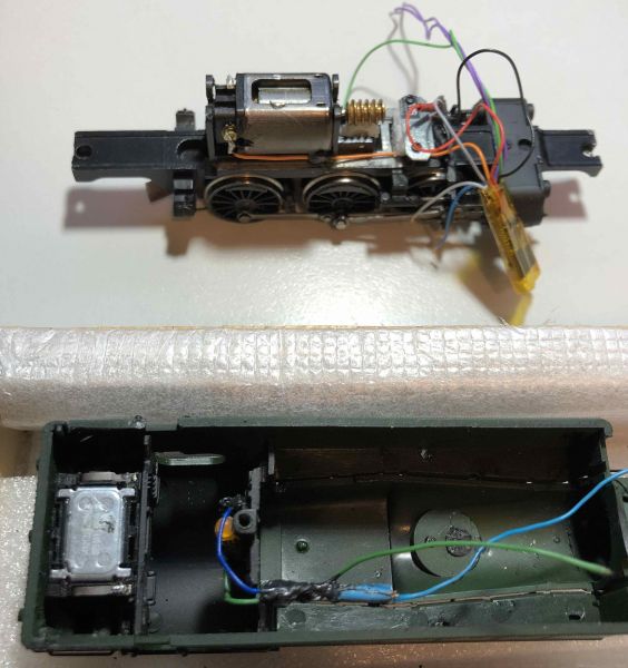
This shows the new speaker in its cavity and the Firebox glow power lines. Speaker wires will be the only addition at the rear.
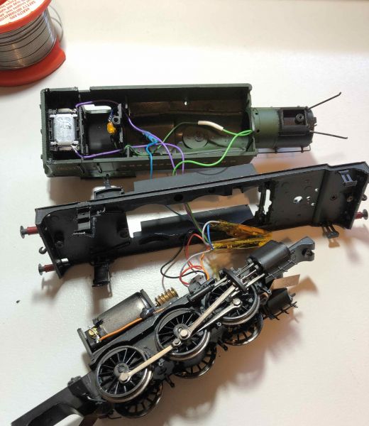
The parts are aligned in the correct order, always the tricky bit to have the correct wires in the right places. Here the new SA sits atop the Sound chip ready to go into the boiler cavity
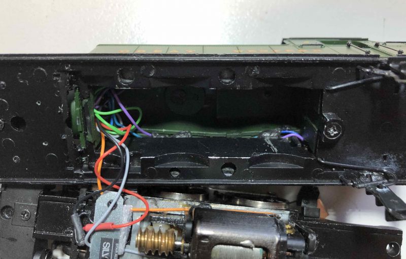
The final step is to arrange the rear wiring into the two side channels (or they'll foul the motor which is a tight fit). They are held in place with Black Tak. A final push of the lose wire spools into the boiler insures nothing can foul the worm gear. It's a tight fit but gets easier with practice. Ask me how I know!
Posted
Full Member
The upgraded Small Prairie sound installation in operation
Last edit: by Colin W
Posted
Full Member
On this one I took my time making sure the base had glued properly after all the cutting done to the webbing. It took two goes before I was happy but lessons learnt….
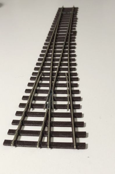
The rest of the assembly was straightforward. Here is a shot before I trimmed the exit rails.
The main road now curves to the right with the crossover nearly straight. A most satisfying outcome and lovely graceful curve leading to my main platform.

Last edit: by Colin W
Posted
Full Member
'Petermac
Posted
Full Member
Thanks.I'm in awe Colin …… :shock: :thumbs
For me it was a very busy and productive day. I think the weather had something to do with it, now we've seen some decent rain and cooler temperatures have set in.
Colin
Last edit: by Colin W
Posted
Full Member
John Dew has asked me if I can explain how to get access to the bunker in this loco. The loco is back together now and so I have to make do with the photos to hand. Fortunately the originals allowed for some enlargement so here goes.
NOTE: In this keep process all screws noted and separate because AFAIR they all differ! I had to bodge a replacement during one of my forays inside
1) Remove the front and rear small screws (under the bogies), this allows the chassis assembly to be pulled down, starting at the rear. (this much is in the loco datasheet if you need a pic)
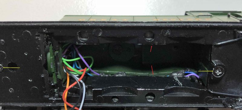
2) to separate the lower Metal section from the plastic moldings of the body work, first undo the two screws shown above by 2 yellow arrows.
The upper plastic sections are also anchored to the base by two lugs at the rear corners of the loco shown below in the 2nd pic taken after separation (bottom 2 red arrows)

Once the lugs are released the entire upper plastic section will lift up easily.
3) The upper sections can be separated with some care if required. The curved boiler and upper firebox come away from the side tanks if you carefully prise apart the side tanks from the inside by 1mm or so. There is a lug either side, shown in both pics above by red arrows approximately half way along the tank sides. Various tubing, stays and handrails also need to be disconnected from their mounting holes to allow the upper section to be lifted off. (getting these back safely is trickier)
This photo from an earlier sortie shows the upper section lifted up but not fully removed. Here the coal load and bunker rear wall have been further separated from the rest of the module.

And if removing the entire top section you end up with this
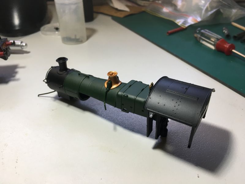
My second photo of the post shows how the wires can be directed from bunker forward around the edges of the cab front wall so, if the bunker space can be opened out by cutting the cross bracing plate from beneath then it may be possible to free up the bunker and use it without the tricky step of separating the two molded sections.
I hope this helps.
Last edit: by Colin W
Posted
Full Member
Moving on to the next B7 Left turnout and applying the lessons learn on #1, the process to build has reduced to little more than a straight kit. The cuts and subsequent gluing of the sleeper base add perhaps 10 minutes in total and the remainder of steps are as per the included instructions. Maybe 45 min in total is required.
Here the photo shows after all the key cuts to the switch blades and the frog is cleaned and wired up to fit. This turnout has a positive curve on the mainline of radius 2085mm. You might note that the template plus tracks doesn't sit completely flat, this because the base is flexible and requires fixing down level at installation. No one has reported any problem with this, it's just a consequence of the design.
Last edit: by Colin W
Posted

Full Member
Thank you for the detailed explanation about accessing the bunker of the small prairie. Very clear and helpful. I will give it a go and let you know how I get on.
Liked the sound video by the way :thumbs
Best wishes
Posted
Full Member
Also, I didn't really comment on the video - that's superb and the control is brilliant - what system do you have ?
The odd pointer to the CV values you use might also help we mere mortels get better performance from ours …………………..
'Petermac
Posted
Full Member
Thanks for all the kind words Peter,Seeing those photos of the decoder fitting Colin, prompted me to ask if you were a surgeon in a previous life ? Wow !!
Also, I didn't really comment on the video - that's superb and the control is brilliant - what system do you have ?
The odd pointer to the CV values you use might also help we mere mortels get better performance from ours …………………..
I've found that the various sorts of fine close work, soldering, kits etc has improved my manual dexterity a lot since I took up railway modelling. Practice makes better I guess.
The video shows what I'd consider normal slow running under DCC control. Clean track and wheels with a modest Stay Alive to see you over minor potential interruptions. The sound chip is the standard smaller ZIMO MX648R and the CVs are as supplied and really applicable just to this chip. Controller is the NCE PowerCab.
As this was a replacement (as detailed earlier), this time I chose the "Immersive Drive" option from Youchoos. If interested see details on their site. It's only an option on Sound chips AFAIK but older sound ZIMOs can be reprogrammed if you know all the CVs to change. I've retro fitted 4 other sound ZIMO chips successfully to set up the Active braking feature.
The most useful / important feature IMO is the active braking function where you have two ways to reduce speed. Use the normal Speed down button to remove drive and just coast slower, then apply the brakes to stop at a rate similar to that defined by the usual CV 4 parameter setting. It quickly becomes intuitive, my 11 yr old grandson picked it up straight away.
Having said all that, the movement shown in the video is just the normal slow startup sequence from stopped. DCC is that good. Glad you enjoyed it.
Last edit: by Colin W
1 guest and 0 members have just viewed this.