Dentith Bridges Underlying Technology
Posted
Full Member
The development Dentith Bridges Digital Control and Accessory Control
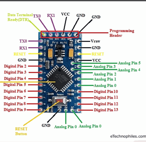
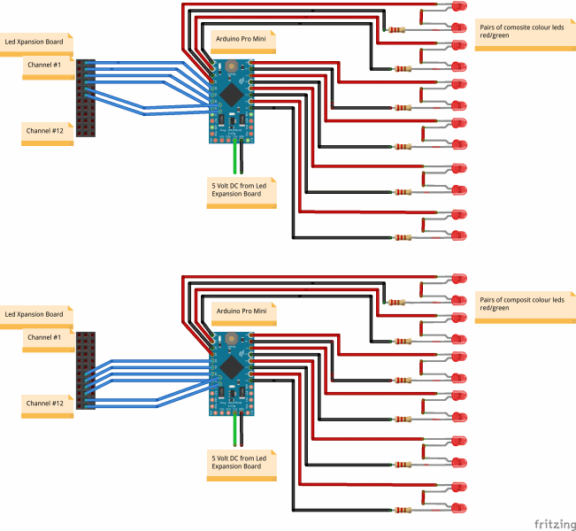
Hi All,Just to complete the above description, below you will see the pin outs for the Arduino Mini Pro and the "cct" diagram showing how the Mini is connected to the led pins on the MP led expansion board. Remember the expansion board is on the feedback network of the MP Multi Panel Processor board.
 Last edit: by Andrewdonald

Posted
Full Member
Been following your turntable design with some interest and the interesting method of the wiring. Not that I'm about to change my setup; it's working well now. The rest of your wiring is well organised - far removed from the "rats nest" I've managed to throw in - well impressed.
Back on 29 April you asked for suggestions about sensors for the initial indexing of the deck. Apologies for the somewhat late response, hopefully you've not moved on beyond this by now. I used a Hall Effect switch on mine (A3144E) together with a small 3mm dia magnet mounted under the deck & it seems to work very well. These switches give a clean changeover action (not all types do) and appears to be repeatable. They can run with a 5v supply so should be fine for your Arduino - don't forget the output of the switch will need a pull-up resistor to 5v.
Keep up with the good work.
Posted
Full Member
Progress will be rather slow, actually nonexistent, for a little while. I had to come down to Sydney for a family occasion and got "caught". Sydney is in a lock down and I can't get back across the border into Queensland, probably for another three weeks or so.
Upside, we are all well and I am getting lots of cuddle time with my Grandson (6 months old).
Cheers,
Andrew
Posted
Full Member
Posted
Full Member
Looking forwards to the next update!
Posted
Full Member
Technically:
I have finalised my decision re control software and I am using Rocrail.
Sticking with the Megapoints gear as already mentioned, but adding MTB1 point motors to the mix
Adopting some of GCA hardware (see the Rocrail link) for "driving" some point motors and obtaining feed back from current sense detectors for block occupancy (and some MERG detectors) - needed for RocRail
I have also adopted the StaRFIish RFID system to provide both occupancy and identity data.
I have adopted an IT support system where by I derive locomotive and rolling stock data from RocRail (RFID and block occupancy derived) and using a MQTT messgae broker and Node Red I can automatically store realtime date into a MS Access data base and develop a stand alone graphc display (Node Red dash board) to display what will be my "hidden" fiddle yard on th elowest level of the layout.
The IT scheme is in prototype status now, but it basically works. I have more to do in refining the database scheme and sourcing real time data out of rocrail, but it is looking good.
Will post more, hopefully with some screen shots, when the system is a little more mature.
Warmest regards,
Andrew
Posted
Full Member
More to come in the new Year.

Posted
Full Member

1 guest and 0 members have just viewed this.