New Layout
Posted
#245878
(In Topic #13583)
Full Member
I am just starting out and would like some help with Wiring this layout. I intend to have it DCC and all Points are Electrofrog from Peco.
Thanks


Posted

Site staff
 Last edit: by Ed
Posted
Full Member
Good start mate…
Unlike others I have done diagrams for, this one was fairly straight forward being DCC from the start.
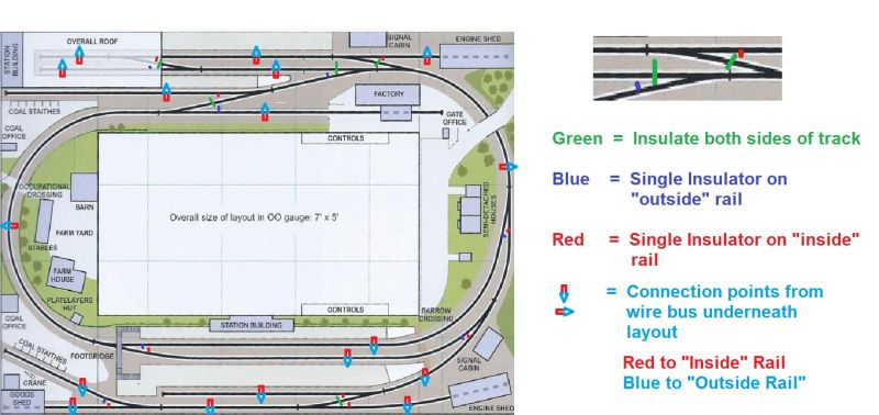
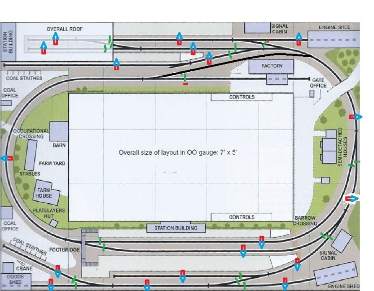
I have lifted the track plan from your post and added insulated joiners to it showing where you will need to put insulated joiners on each of the inner, outer or both rails.
The diagram itself is a bit small and you may miss a detail so I would suggest you enlarge your screen or copy and paste the diagram on to a Word Processor page and enlarge it .
Wiring it would also be fairly straight forward in that you would have two different coloured wires forming a loop under full length of the layout. I have lifted the next section from a previous post.
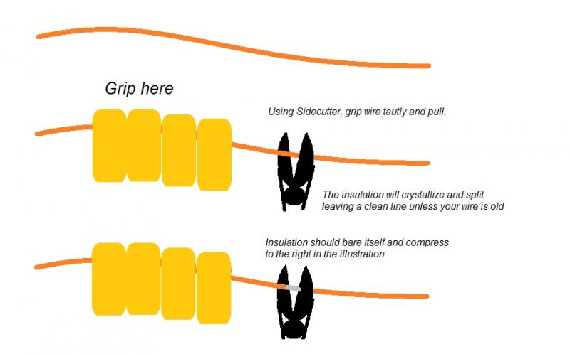
Being an electrician by trade helps me but if you use a pair of side cutters, hold the wire securely with one hand and grip the wire with the side cutters just slightly tighter than the diameter of the plastic and slide it. The insulation will shear at that point and you can "bunch it up" exposing enough wire to wrap around the tee. Join and solder. You might need to practice a few times on some extra wire as you are bound to cut through it the first few times. I do not use strippers as there are many situations that you cannot get them into place.
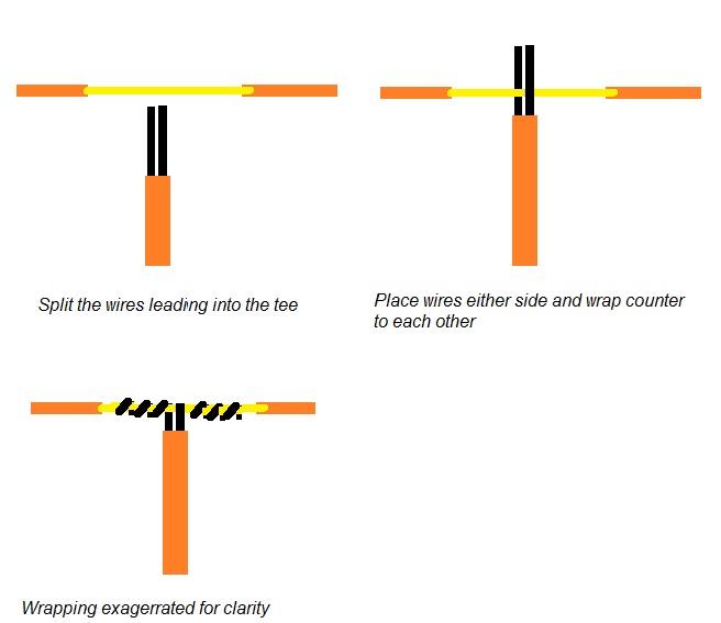
If you are making a Tee it is a good idea (I think anyway) to do a tee wrap before soldering… see the illustration!
With your DCC controls, you would also splice your wires from your controller master station into each of the two wires in the loop around the layout. Do you have one "station" or two DCC station for your control areas?
Hope this is clear enough to help!
Cheers from Australia
Trevor
Edited 7 hours later!
PS Pardon the edits as I seemed to have a bit of a flu this morning when I saw the original post- feeling a bit better at the moment and hope the edits make this make more sense.
Last edit: by xdford
Posted

Full Member
Electrfofrog usually means Peco points. It's worthwhile doing some reading on why they are not 100% DCC-compliant, and how to convert them so they are. Technically they are what is called upower routed. Not desirable. Insulfrogs are actually better, they just do not look so good.
Your track plan has three distinct regions. It might be worthwhile isolating each one into a power sector (block in DC) so that a short does not shut the whole layout down.
Although you can program locomotive decoders on any part of the layout, it is convenient and safer to have a programming track. Trevor has covered this in other posts. One of the coal staith tracks would do.
If you are powering the points you should consider isolating the frog and using a switch Iinked to the motor that changes the polarity as required. If you do convert to fully DCC compliant with isolated and switchable frogs you do not need isolators.
It's worthwhile just doing a point with three pieces of track and practice wiring it to DCC so you get the hang of it. You have 13 turnouts on the layout, that's a lot for what is a small layout, worthwhile buying 14 and using one to get it right before laying track.
Nigel
©Nigel C. Phillips
Posted
Full Member
As Nigel points out, short circuits would be easier to detect if the sections are switched so I have added another two sections and made all the insulated joiners doubled to rails where those joiners are applied,
Here it is

Nigel, while 13 points may seem a lot on Grahams layout, I have 22 on my 4 x 8. Had I followed the original E E Seely plan in toto, I would have had 23 or 24. Most of mine are insulfrogs by virtue of age and common rail wiring.
However your point with short circuits is well founded as I now have all metal wheelsets under all but a few freight cars and there have been one or two occasions where those wheelsets have created a short with their respective blocks running in opposite directions resting in the insulated joiner gap but I can count those incidents on one hand in about 25 years or so of having all metal wheel sets.
Hope this all helps
Cheers
Trevor
PS Graham if you need a wiring diagram let me know but I would suggest looking at http://yourmodelrailway.net/view_topic.php?id=9970&forum_id=21&highlight=help+needed+with+electrics OK it is for a DC layout but the principles apply - if you need a purpose made diagram, let me know! Trevor
Last edit: by xdford
Posted
Full Member
Point I was making was that diving straight in and wiring 13 points for DCC on a small layout (and correcting the woeful deficiencies of power-routed points and frogs) might be a tad daunting for somebody starting out. Hence my suggestion to do a tester.
Following on from the wiring plan that Trevor provided, some questions you could consider before starting the wiring.
How many locomotives running at once? Modern or old stock? This will dictate what power you need and what diameter wiring to use. Modern locomotive engines draw about 0.4-0.5A, so a 2A system is good for 3 trains (such as the NCE PoweCab). Old stock with inefficient motors can draw up to 1.0-1.5A, more on start-up. They are DCC doable, but need decoders suitably rated.
Are you planning on buying locomotives with installed decoders, or going to install yourself? New stock is usually easy, old DC stock can be…challenging.
Will you need regulated DC for point motors (solenoid, server or stall), signals, lights, etc.? Three schools of thought on this - controller everything through DCC (which means determining what the draw will be - see first point), DCC for the track/locomotives and DC for point motors/signals etc., or manual lever control (wire-in-tube for example)? If you are planning on solenoid motors you will probably need at least one capacitor discharge unit (CDU). Solenoid motors are current hogs compared to stall motors such as the Tortoise or Cobalt ranges. Having a separate DC bus circuit for accessories is in many ways unavoidable. Plan ahead on this one. Even if you only use it for interior lights in buildings.
Nigel
©Nigel C. Phillips
Posted
Full Member
I was planning on trying to do everything through DCC, But on reading BCDR's last post I think I will be now looking at using a seperate DC system for Point motors and such.
Thanks to Xdford for the wiring diagram a big help for a novice like me.
Will post some pics as I get more done.
Posted

Full Member
regarding insulfrog vs electrofrog (and I think there are a new generation of PECO life frog types of which I know nothing).
I started with insulfrog points knowing no better then saw many experienced modelers favouring live electrofrogs. I soon found out why with my small 0-6-0 locos regularly stalling on points long and short. The annoying feature of these locos is that the front axle can be over one dead section in the point and the rear axle in the frog (or vice versa). Either way unless the point is absolutely level contact will be lost.
However I do have the consolation that point switching requires no power switching.
More recently as shown here:
http://yourmodelrailway.net/view_topic.php?id=16111&forum_id=21&page=1#p288811
and the #12 post just below this
I've moved to sound / DCC where continuous power is a must and fitting stay alives as part of that project has fixed poor running over insulfrogs with even the worst of my small wheelbase locos. So (IMO) if you can live with the poorer aesthetic of the plastic frogs you can have good running and far less worries with wiring / switching.
Colin
Last edit: by Colin W
Posted
Full Member
You are welcome… if you need a diagram to do the separate areas, let me know but as Nigel is also saying, you would need to think about how you want to operate your trains. The wiring diagrams are indeed flexible so I am wondering if what Nigel envisages is the same as I see it by mentioning "three distinct regions"?
Your points wiring is a totally separate circuit whicKen on this forum and you can see on http://yourmodelrailway.net/attachment.php?id=582
While it looks complicated, it is not so much as slog work and a bit of patience to do one wire at a time and ticking them off as you go from your master plan is the key. The discussion starts at http://yourmodelrailway.net/view_topic.php?id=9494&forum_id=6&highlight=help+needed+with+electrics#p175147
for your interest,
Cheers
Trevor
Posted
Full Member
Re Trevor's comments, you have three distinct power regions, but the plan never had this in mind. The top part until it reaches the junction with the upper coal staithe siding, the central tail chaiser, which unfortunately involved the staithe track, and the lower part from the junction to the single platform line/coal staithe/engine shed/good shed.
Power regions in DCC involves some electronic short-circuit protection that shuts off power to the region involved but keeps power running in the other region. Seamless and switchless in operation. The idea is that a short in one does not affect the others.
Shorts generally occur where there are lots of points, especially cross-overs. See how you go first, protection can be added afterwards.
Before you commit to any track plan it is worthwhile running through the operations - engine runarounds, brake van drop off locations, etc.
Major issue with Peco points, aside from the power routing one, is the length of the frog. Up to nearly 5" depending on which type.
What are you planning on using for the track - code 100 or 75?
Nigel
©Nigel C. Phillips
Posted
Full Member
These are the point motors I have if that helps any. point motors
I am thinking of operating them via a panel with either switches or the stud and probe method.
Any help there would be appraciated.
this is me starting out ( all the gear No idea lol)
Posted

Site staff
Ron
NCE DCC ; 00 scale UK outline.
NCE DCC ; 00 scale UK outline.
Posted
Full Member
Just wondering if the Data sheet is spelling out 1 Ampere draw whether that is 1A at stall point or normal running. I take it that the motor needs to be switched off once it has completed its action of throwing the points?
Has anyone here used the small servo motors that can be bought on Ebay for a couple of dollars each as point motors?
Nigel, would the following variation of the plan be more in keeping with what you envisage avoiding the siding problem? Not to scale of course and not shown wired with insulators or adjustments to the power feed ins but might help with the zoning you are referring to?
Graham, might I suggest that you get a copy of early copy of the Trainz computer program and make a mockup of this layout even though it will be way to generously proportioned. You could then play with the operating possibilities for yourself and see if you like it and modify any shortcomings if, as and when you find them!
Just thoughts!
Cheers
Trevor
Posted
Full Member
Posted
Full Member
Graham: Yes, play around with train movements and see where the issues will be. Engine, 2 coal wagons, brake van. Pick up 2 empties, drop 2 full ones at either of the staves. You might want to consider a storage / fiddle section.
I was more interested in how you got in and out of the layout.
Conrad: 1A? Most stall motors use 0.05 or less. What's with the diodes?
Nigel
©Nigel C. Phillips
Posted
Full Member
That would be drop on all fours and crawl under. Unless anyone can figure out an easier way.
Also I have removed the Points section at the top station end, thought it pointless (excuse the pun) I was thinking of making the top section as a Main Line Up and Down section and do away with the station terminus, Then maybe the bottom section could be a storage or fiddle section ???.
Posted
Full Member
I was only reading the spec sheet which read 1A not .1 or less Ampere. Graham I take it you are having second thoughts about your plan which I presume you may even be checking with the Trainz program.
If you are for the most part a "lone wolf" operator as I am for 99.9% of the time, you could modify the top station to being a through station and alternate which station you use as a fiddle yard on the day that suits you.
I notice you have a few lengths of flex track and given my "druthers" I would have made the front length of track a very slight outwardly curved track with about a 100 inch radius or so to dispel the nature of a train set straight with the two parallel tracks flowing with it. This does give the impression of the layout being bigger than it actually is.
My layouts operating scheme is at http://xdford.freeasphost.net/stag06.html and I also have an article copy by the original planner about building and operating my layout which if you PM me with an email address, I can send you … nothing commercial in it!
If I were to ever rebuild it and go for an around the operator as you have the board for, I would use a similar scheme although the proportions would change especially if I went into British modelling, but I would operate it similarly to what I do now.
Let us know what you want to do… we are all here!
Cheers
Trevor
Posted
Full Member
"I was more interested in how you got in and out of the layout."
That would be drop on all fours and crawl under. Unless anyone can figure out an easier way.
Also I have removed the Points section at the top station end, thought it pointless (excuse the pun) I was thinking of making the top section as a Main Line Up and Down section and do away with the station terminus, Then maybe the bottom section could be a storage or fiddle section ???.
Hi Colin,
Digging up the garage floor is out then? Any chance a mechanic's dolly will fit? You will be doing the wiring on you back, not ideal. How about a lift-out or hinged section on one side? Did you build the base as one unit, or is it modular? You could raise the height to something that allows a bent shuffle. Any small children around? Height is very subjective,
Nigel
©Nigel C. Phillips
Posted
Full Member
A lift out or hinged section on one end would be the easiest solution as the Baseboard is one I made my self and is all one section. The best place to have a lift out or hinged setion would be the right hand side end, as that is the end near the garage back door access.
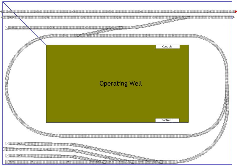
Have been taking your thoughts on board and have revised the layout with Operations in mind.
I think this could give us more options for operating plans.
Posted

Full Member
On your revised plan the top track is not connected to the rest of the layout?
Cheers
Andy
Andy
1 guest and 0 members have just viewed this.