More on Decoupling Magnets
Posted

Site staff
My Trials on magnet placement for Kadee Couplers
A similar concept that Kadee uses#308 Under-the-Track Hidden Delayed-Action Magnetic Uncoupler - HO, S, On3, On30, O Scale
Ron
NCE DCC ; 00 scale UK outline.
NCE DCC ; 00 scale UK outline.

Posted

Full Member
A similar concept that Kadee uses
Hi Sol,
Not really. This video
Inconvenient Truth About Kadee Uncouplers
shows that the Kadee undertrack decoupler causes axle grab (on UK stock from 6:20min in the video), as well as grabbing if you have a steel body weight.(from 4min). This is due to the Kadee field being perpendicular to and between the rails. (As per type (1a) in my magnetic field diagram from my earlier post)
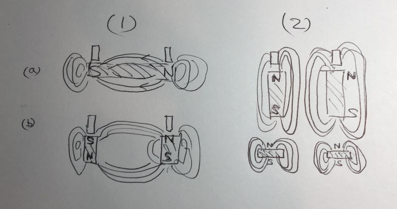
Later in the video the author suggests solutions but appears not to realise the importance of avoiding a magnetic field which is perpendicular to the rails. He may have set his polarities correctly by accident because if you have all Norths one side and Souths the other (type (1b)) you're just replicating the Kadee design and will get axle grab.
I have a video I'll post of the difference between the two magnet configurations. The difference is striking.
 Last edit: by Colin W
Posted
Full Member
1) All same Poles facing up under both rails
[yt]8N0CT0gDjT4[/yt]
2) All Norths up one side Souths on the other
[yt]qsjuE02sLFE[/yt]
There is a sound scientific reason for having the magnetic field restricted to the area around each rail rather than spanning the entire space between them. The side fields are enough to attract the uncoupling hangers which are angled either side but produce far less attractive force in the centre of the trackway where it's just a nuisance..
The difference is remarkable which makes it all the more amazing that it's not been noted prevoiusly AFAIK.
Last edit: by Colin W
Posted
Full Member
When you use a perpendicular magnetic field device or configuration it will be relatively insensitive to positioning as you depend on having the field across the tracks. This clearly suits a commercial solution and simple DIY solutions with Neo magnets.
When you depend on magnetic attraction only from below the rails with matching polarity, getting your positioning is more demanding. However a little research will work it out with the magnets you plan to use and then stick to that design / strength and it will be replicable. I'd suggest good strong N52 grade 20mm * 10mm from a reliable supplier; caveat emptor, there is a lot of rubbish out there in the i-marketplace.
In my case I cannot possibly replace all my wheel / axles, some of my wagons have embedded and inaccessible iron body weighting (and I want to use more), nor could I live with the axle drag I saw with my early perpendicular magnet solution reported early on in this Topic.
Posted
Site staff
A bar magnet underneath rails is the way to go but like the electromagnets, one has to work out where they are going before laying track.
Some of my crew like permanent magnet uncoupling, others don't because often false uncoupling occurs when pulling a train out of a siding & having to stop for any reason, you can bet your last $ that a couple of wagons will stop over the magnets leading to uncoupling.
Ron
NCE DCC ; 00 scale UK outline.
NCE DCC ; 00 scale UK outline.
Posted
Full Member
agreed not quite as easy.I see what you mean Colin - cube magnets will be a tad harder to instal coz one has to work out which face is north/South ! ………………….
Whichever magnets you're using, the best way to get all the same poles aligned "UP" for my method is to start with a stack of all your required magnet blocks attached standing up on your intensifier plate (a strip of thin steel) and slide all but the bottom one of the stack to one side (see note 1). When magnets all have the same pole "up" the steel strip prevents them jumping back together, however they do repel each other so you end up with a modest gap between individual units.
The magnets for the other rail can be assembled the same way, ensuring the same pole is up for both sides!
The steel strip serves an ongoing purpose of intensifying the upward field, while the field from the lower poles is constrained inside the strip.
Note 1. These block magnets may be unusual for those who have not come across them before. The most common type viz. a flat block has its poles on the two largest faces, i.e mm apart quite unlike a traditional Bar Magnet.
Hence a stack of them is aligned like this where the line is the boundary between blocks.
N
S
N
S —> slide sideways then down
N
S
your aim is to separate them by sliding them apart. The S face stays down ensuring it ends up on the steel plate and the next magnet's N is UP like its neighbour. This method will work perfectly well even with cuboid magnets since they stack according to their polarity.
I think it is best to build two separate strips, one for each rail so there is no conduit for under rail magnetic field. This may be unimportant but easy to avoid and also allows you to incorporate the separate strips into a module with the correct spacing. Care is required! the loose strips will snap together ferociously if they are not carefully kept apart until assembled in a suitable holding device. I'll post my details soon.
Last edit: by Colin W
1 guest and 0 members have just viewed this.