Kevin's Inglenook Junction
Posted

Full Member
Two Planks Become One

I am not adding anything here as Kevin is in safe hands but here is (I think) Kevin's trackplan in case it helps. The photos he posted suggest that the two lines of track are not conected.
I think the power feeds should be at F1 and F2 - if not, then that might be the fault?????
Over and out
Barry
Shed dweller, Softie Southerner and Meglomaniac

Posted

Full Member
So what were the results? If you did wire them like that I think that as soon as you connect the board to the main bus the polarity of the frog is wrong. The track rails couldn't care less. You would need to swap bus the wires going in into the switch. If you remove the frog wires from the switches does it still short?
Some pictures and diagrams would help, otherwise it's difficult to understand what is going on.
As I and others have said, start again from the beginning, testing as you go every time track or point is laid.
Nigel
©Nigel C. Phillips
Posted

Site staff
Cheers
Matt
Wasnie me, a big boy did it and ran away
"Why did you volunteer ? I didn't Sir, the other three stepped backwards"
"Why did you volunteer ? I didn't Sir, the other three stepped backwards"
Posted

Full Member
Staying on the thread Kevin.
Posted
Full Member
Hi Kevin,
I am not adding anything here as Kevin is in safe hands but here is (I think) Kevin's trackplan in case it helps. The photos he posted suggest that the two lines of track are not conected.
I think the power feeds should be at F1 and F2 - if not, then that might be the fault?????
Over and out
Barry
Thanks to Barry for the plan. This is where it gets interesting - how did you wire it? You have in essence 4 power districts (blocks in DC) 2 on each board - that really should be wired separately with one common wire and 4 separate wires with circuit breakers, both connected to the PCP. That way each district is separate and a short in one will not affect the others. Or the Powercab.
Nigel
©Nigel C. Phillips
Posted
Site staff
Cheers
Matt
Wasnie me, a big boy did it and ran away
"Why did you volunteer ? I didn't Sir, the other three stepped backwards"
"Why did you volunteer ? I didn't Sir, the other three stepped backwards"
Posted
Full Member
Kevin
Staying on the thread Kevin.
Posted
Full Member
All I'd recommend is to not have all of those wires exposed and once you are happy with bits insulate them with tape.
Posted
Full Member
Staying on the thread Kevin.
Posted
Full Member
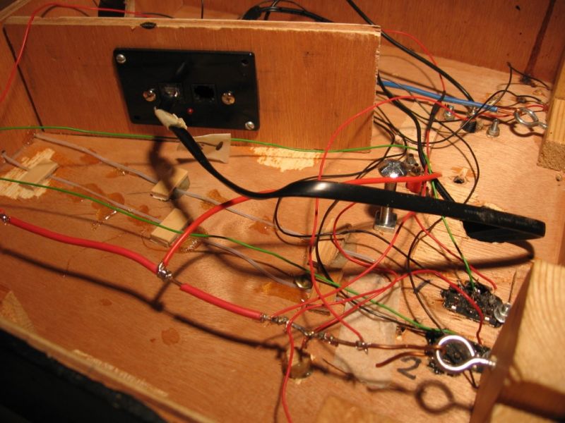
That looks… interesting. As you have WIT for the points all that is track plus connections to the DPDT switches for the frogs. You have a lot of bare metal. This just might the be an opportune moment to start with a clean board and plan it out using power districts and some short protection for the Power Cab.
What gauge wire are you using? How did you color code the bus and droppers? I see red coming off black, red coming off red, black coming up off blue..red and blue look to be the bus wires as they are kept in place with ring screws. Any reason why the PCP is in the inside rather than on the side wall?
Nigel
©Nigel C. Phillips
Posted
Full Member
 Last edit: by Passed Driver
Staying on the thread Kevin.
Posted
Full Member
Staying on the thread Kevin.
Posted
Full Member
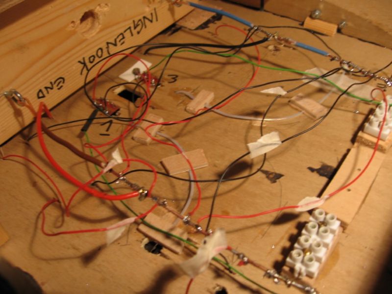
Thanks. Pretty logical if unconventional, whatever works best for you. NCE recommend 16 or 18 gauge for the bus for a 2 Amp system and a small layout, 20-24 for the droppers. It is important, as the thinner the wire the greater is the voltage drop. Best to keep droppers the same length.
Difficult to tell from the photos, are the switches powered from the bus or the rails? Grey is the wit?
I gather you do not have a circuit breaker to protect the Power Cab.
Nigel
©Nigel C. Phillips
Posted
Full Member
Staying on the thread Kevin.
Posted
Full Member
I think you meant that the feed to the frog was green. I see red and black going in.
I just caught your comment re the plug. This is the NCE cable? That is not a standard RJ12 telephone/CAT cable, and is custom made for NCE to carry 2 amp. You could put a new end on, but it will be cheaper to get a replacement unless you can get the loan of a crimper.
Nigel
©Nigel C. Phillips
Posted
Full Member
Hi Nigel. Thank you for your reply. The “Telephone like plug†comment was for anyone that is unfamiliar with the NCE Powercab set up. In my pursuit of short circuits, my wiring that is under the baseboard may look like a telephone 📞 exchange? but I can assure yourself and any interested parties that the Green Wires have remained constant and do control the points via the DPDT Slide switches . Best wishes KevinHi Chris. Thank you very much. But, there’s more, a new fault, the “ telephone like plug “ doesn’t want to stay in position, because the plastic type spring/ latch doesn’t clip any more, but due to circumstances beyond my control my bank card has been cut up. Best wishes Kevin
Staying on the thread Kevin.
Posted

Site staff
Points to there being a fault having developed in one or other (or both) switches.
You've probably already done this, but for clarity, you can check the switches with your multimeter.
With the multimeter set to 2000 ohms (resistance), if you touch the probes on something that has no electrical connectivity you'll get a 1 on the display.
In this case air.

If you touch something that will pass a electric current, in this case a piece of rail, you'll get readings on the display. They may well jump about and keep changing, but the display won't stay on 1.
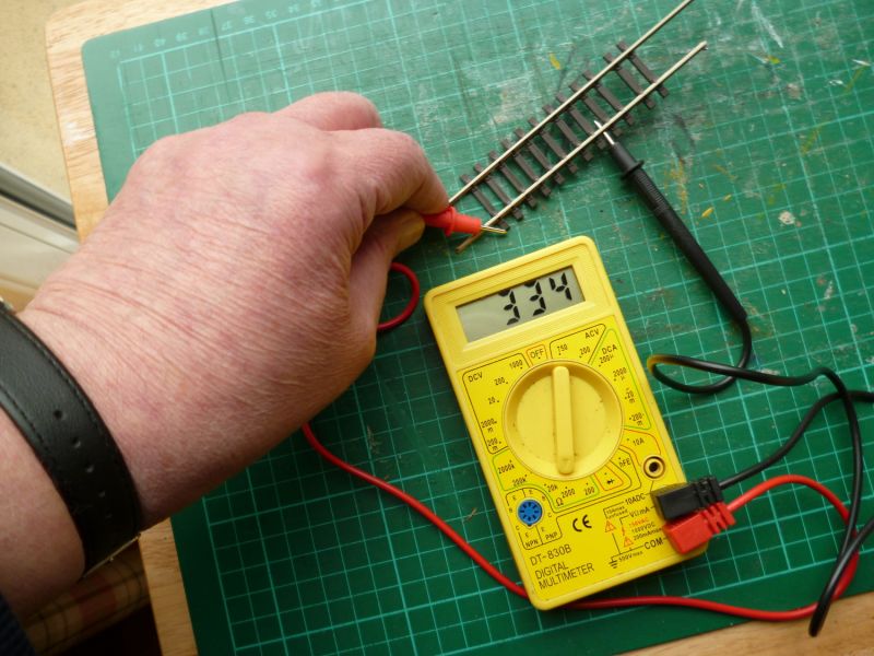
If you take your multimeter and touch the center connection of a slide switch with one probe and then touch the left hand connection with the other probe, you'll get either a 1 or some sort of reading.
If you leave one probe on the center connection and then move the probe from the left hand connection to the right hand connection, you should then get the opposite reading from what you got when touching the left hand connection. (i.e either a reading or 1).
That is, one connection should show a reading and the other one should just show 1.
If both the left and right hand connections give a reading, the switch is faulty.
Don't know if this helps, but it can be used all around the layout. Anywhere where two bits of rail are isolated with a IRJ should show 1 when the probes are touching the rails each side of the IRJ.
Ed
Posted
Full Member
Staying on the thread Kevin.
Posted
Site staff
Connect them together and you get a fault
If you disconect the red wire from any one point you still have the fault (doesn't matter which one)
If you discontect the red wire on the SECOND point on that particular board the fault goes away
Wasnie me, a big boy did it and ran away
"Why did you volunteer ? I didn't Sir, the other three stepped backwards"
"Why did you volunteer ? I didn't Sir, the other three stepped backwards"
Posted
Site staff
Disconnect the Powercab (if it isn't already) before you test the switches, and as you test each one, then slide the switch (i.e. change the point) and check that the opposite connection now has a reading and the other shows 1.
Matt. I need to ponder that. Very odd that the fault only goes away only after disconnecting both point switches.
Suggests the feed, but it won't harm to eliminate each individual component in Kevin's set-up.
(By hook or by crook, we'll get him going)
Ed
1 guest and 0 members have just viewed this.