Peco Electrofrog L/ H point

Post

Posted
Rating:
#240492 (In Topic #13319)
Avatar
Full Member

Appears to be dead

Hi All. I really don’t believe it. I have modified the point as per instructions, I have cut out the underside wires, soldered a wire from the stock rail to the switch rail, I am using insulated joiners on the frogs.And when a Loco arrives at the point it stops dead, I even tried electrical jumpers in addition. And still nothing, I got out my “ trusty led tester gadget from Gaugemaster “ , wouldn’t you know that indicated that the point was dead.
I phoned  Peco technical advice expert, he was off today.  Please advise. Best wishes Kevin 

Last edit: by Passed Driver


Staying on the thread Kevin.
Online now: No Back to the top

Post

Posted
Rating:
#240496
RFS
Full Member
Are you applying power to the frog via a suitable polarity switch? If not the frog will be dead. 

Last edit: by RFS


Robert
Online now: No Back to the top

Post

Posted
Rating:
#240497
Avatar
Full Member
Hi Robert. Thank you for your reply. Yes, and it is just the I always do it. And I tested the frog wire for connectivity  If that is the correct term. and all seems to be okay.  Best wishes Kevin 

Staying on the thread Kevin.
Online now: No Back to the top

Post

Posted
Rating:
#240499
Full Member
Any photos Kevin?
Terry
Online now: No Back to the top

Post

Posted
Rating:
#240500
Sol
Avatar
Site staff
Sol is in the usergroup ‘Super-moderators’
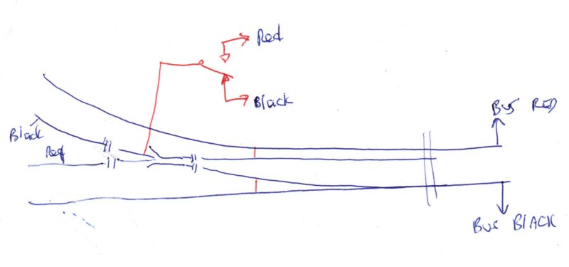
Kevin, I assume your wiring is like this?


the red wiring is what you should have done so the frog is not dead.  The red switch  would be part of your slide switch that operates the turnout tiebar.

Ron
NCE DCC ; 00 scale UK outline.
Online now: No Back to the top

Post

Posted
Rating:
#240501
Avatar
Full Member
Hi Kevin,

Have you used a multimeter to check current and polarity?  Stopping dead sounds like the switch is wired incorrectly. Positive wheel meets negative frog. Does the controller light up? Does it run through with a dead frog? Is the slide switch toasted? Most are low amp, a short could cream cracker it.


Nigel


©Nigel C. Phillips
Online now: No Back to the top

Post

Posted
Rating:
#240503
Avatar
Full Member
Hi Terry. Thank you for your reply. Me and photos? I have been playing trains instead of building scenery, the only photos are of a very basic Inglenook, under my name in the gallery. But I do hope to do some sort of scenery once I get the fiddleyard up and running.  Best wishes Kevin 

Staying on the thread Kevin.
Online now: No Back to the top

Post

Posted
Rating:
#240504
Avatar
Full Member
Hi Ron. Thank you for your reply. That is roughly it, but it occurred to me tonight, that that I may have to swap the red and black wires? I use a green wire from the frog to the centre contact on a DPDT Slide switch with the red and black from the outer two contacts to the bus. Following the thread by Gary. It is getting late for soldering tonight, but I will investigate it in the morning.  Best wishes Kevin 

Staying on the thread Kevin.
Online now: No Back to the top

Post

Posted
Rating:
#240505
Avatar
Full Member
Hi Nigel.  Thank you for your reply. In a word no. What I use is a bit crude ( battery/ buzzer in a box with two wires and crocodile clips) but, I do own a multi meter. I did find a thread online about making a device which I did, but, I cannot remember how to use it. The Loco didn’t get as far as the frog. I have had a similar occurrence before, when the controller flashed, but, not this time. I will report back to everyone after a nights sleep 🛏.  Best wishes Kevin 

Staying on the thread Kevin.
Online now: No Back to the top

Post

Posted
Rating:
#240507
Avatar
Full Member
Hi Ron, Nigel, Robert, Terry, previously I had a similar circuit fault, and the answer was to swap the red and black wires, which I did, but, this time it only made the situation worse by causing a short and causing the “ cab “ to flash.I have now returned the wires to their original contacts . Could the point be faulty??? Best wishes Kevin 

Staying on the thread Kevin.
Online now: No Back to the top

Post

Posted
Rating:
#240508
Sol
Avatar
Site staff
Sol is in the usergroup ‘Super-moderators’
It is better to use a multimeter to see if connections are correct and that power is getting to the frog via your switch.

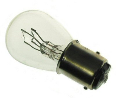
But if you are not good with a multimeter, then a 12v car globe will do.

Ron
NCE DCC ; 00 scale UK outline.
Online now: No Back to the top

Post

Posted
Rating:
#240509
Avatar
Full Member
Hi Ron. Thank you again. You are correct I am no good with a multi meter. The man from Peco was at work today and he said it must be the switch that is the problem, to which I replied I have never had a problem with the switches, are you certain that it cannot be the point? I don’t know what you mean by a 12 volt car globe?Best wishes Kevin 

Staying on the thread Kevin.
Online now: No Back to the top

Post

Posted
Rating:
#240511
Avatar
Full Member
Hi Kevin,

It stops before the frog? Do you mean at the junction between the closure rails and the frog?  what about the other exit side. If it stops there the frog section is dead.

There are plenty of instructions on the web for a multimeter. 5 minutes prodding and poking and you will know exactly where the fault is. The points, the wiring or the switch. IMO a must have piece of kit. And very easy to use. 

Check the points out of the box first. Then after wiring. Then after installation. Then ballast, not before.

If the turnout came with a pre-installed frog wire that could be the issue. It comes adrift very easily as it uses tinned wire. And to make sure insulate it with some heat shrink.


Nigel

©Nigel C. Phillips
Online now: No Back to the top

Post

Posted
Rating:
#240512
Avatar
Full Member
Hi Nigel. Thank you again. I screw a terminal block under the baseboard, and when thread the frog wire through I connect the two wires to the terminal block, which makes it straight forward to remove. As for the pre installed frog wire since I laid the point I have tested the frog to the switch, avoiding the wiring. Best wishes Kevin 

Staying on the thread Kevin.
Online now: No Back to the top

Post

Posted
Rating:
#240515
Avatar
Full Member
As Nigel mentioned Kevin - if, as you say, it stops before the frog, it's not the frog.

Coming which way does the "stop" occur ?

If it's from the toe, then it seems the point is dead.  If it's from the frog end, then it's the frog.

If you're using insulated joiners on the toe end, do you have a feed to the point itself ?  Have you wired both closure rails to the stock rails ?  If not, then it could be a lack of contact there.

If every bit of metal on the point is connected to some kind of a feed (direct or via the switch), then it has to be the switch.  That's the only place there is a "missing link" …………………………….. :???:

If changing the switch wires causes a short, then your original wiring was correct but there is a missing supply somewhere.

It would be so much easier for all concerned, if you could post some photos - it's not difficult.   Trying to imagine what you've done is nigh on impossible but with a photo, we'd spot the problem immediately……………………………. 

'Petermac
Online now: No Back to the top

Post

Posted
Rating:
#240517
Avatar
Full Member
Hi Petermac.  Thank you for your reply. When I soldered the wire from the stock rail to the closure rails l extended it to the bus, I have tested the switch and that seems okay too.   I will go through it all again tomorrow, I am uncertain what good photos would be, but I refer you to Ron’s diagram, and that is how I wired my point.  Best wishes Kevin 

Staying on the thread Kevin.
Online now: No Back to the top

Post

Posted
Rating:
#240529
Sol
Avatar
Site staff
Sol is in the usergroup ‘Super-moderators’
[user=1801]Passed Driver[/user] wrote:
Hi Ron. T? I don’t know what you mean by a 12 volt car globe?Best wishes Kevin 

12v car globe is what is used for head & tail lights in cars etc
Image

(Click to enlarge)


Ron
NCE DCC ; 00 scale UK outline.
Online now: No Back to the top

Post

Posted
Rating:
#240530
Avatar
Full Member
Hi Ron. Thank you again. I thought that all car lamps were “ Sealed Beams “ .   Best wishes Kevin 

Staying on the thread Kevin.
Online now: No Back to the top

Post

Posted
Rating:
#240531
Sol
Avatar
Site staff
Sol is in the usergroup ‘Super-moderators’
and such globes can be used as overload protection
http://www.members.optusnet.com.au/nswmn/1156.htm

similar to DC days

Ron
NCE DCC ; 00 scale UK outline.
Online now: No Back to the top

Post

Posted
Rating:
#240533
Ed
Avatar
Site staff
Ed is in the usergroup ‘Super-moderators’
As Petermac asked Kevin, "Coming which way does the "stop" occur ?"

If the toe of the point is connected to the adjacent piece of track with normal rail joiners, even relying on them for connectivity, I would expect a loco approaching the toe to continue onto the point, however you've wired the point.


Ed

Online now: No Back to the top
1 guest and 0 members have just viewed this.