Making points...work...
Posted
#239555
(In Topic #13260)
Full Member
BUT…since childhood and Peco points, I have never had points or much other trackwork as I have never had a layout since. Lantern Yard has a little narrow gauge to represent an 18" line. It is effectively a run round loop. I have made the points today, no trouble, using any old bits of PCB as sleepers as the points will be covered over completely in "soil".
My big query is…how do you clever techy types keep the switch rails together without shorting them out? And do I have to wire them (the points) in some way? There would only be 2 engines in the set-up at any time and one would be in the dead section at the engine shed end.
I have absolutely no idea how to make points work. I know I don't like trains to move, but this might be used by Nev Kent to show off his range of 9mm chassised 09 models that I've made for him and he'd probably want them to move.
Many thanks in advance.
Martin
Manifestly it is better to use simple tools expertly than to possess a bewildering assortment of complicated gadgets and either neglect or use them incompetently. ( L.T.C.Rolt)

Posted

Site staff
http://yourmodelrailway.net/view_topic.php?id=8360&forum_id=21
http://yourmodelrailway.net/view_topic.php?id=5814&forum_id=6
Now Nigel, BCDR has done something like this recently so he wll no doubt chip in.
Ron
NCE DCC ; 00 scale UK outline.
NCE DCC ; 00 scale UK outline.
Posted
Site staff
Step by Step: Hand Laid Turnouts | Model Railroad Academy
this has lotsa photos
Building Turnouts
hand laid turnouts
Ron
NCE DCC ; 00 scale UK outline.
NCE DCC ; 00 scale UK outline.
Posted
Full Member
Martin
Manifestly it is better to use simple tools expertly than to possess a bewildering assortment of complicated gadgets and either neglect or use them incompetently. ( L.T.C.Rolt)
Posted
Site staff
http://yourmodelrailway.net/view_topic.php?id=1645&forum_id=6
or
https://brian-lambert.co.uk/Electrical.html#live
Ron
NCE DCC ; 00 scale UK outline.
NCE DCC ; 00 scale UK outline.
Posted
Full Member
Martin
Manifestly it is better to use simple tools expertly than to possess a bewildering assortment of complicated gadgets and either neglect or use them incompetently. ( L.T.C.Rolt)
Posted
Site staff
https://brian-lambert.co.uk/Electrical.html#Track
I am assuming DC operation ?
http://www.rail.felgall.com/pfo.htm
The Model Shop for Big Imaginations | Gaugemaster
Wiring a DC loop and siding help please?! - Electrics (non-DCC) - RMweb
wiring a simple passing loop with home made points - New Railway Modellers Forums
Ron
NCE DCC ; 00 scale UK outline.
NCE DCC ; 00 scale UK outline.
Posted
Full Member
it seems I'vce asked the question before on another forum. Forgot all about that one!. The RMweb one comes closest to what I can understand. The others are way too complicated because they go through loads of track plans I don't need and fog the eyesight before I even get to what I have or something like it.
Many thanks for your help.
Cheers,
Martin
Manifestly it is better to use simple tools expertly than to possess a bewildering assortment of complicated gadgets and either neglect or use them incompetently. ( L.T.C.Rolt)
Posted
Full Member
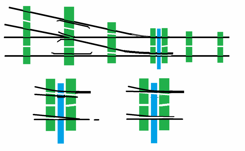
I have built a number of points over the years and even with a single slip ( now that was fun to work out the gaps!!) with a long gone friend of mine. I have none loose at the moment so forgive the drawing. The green represents a few PCB sleepers, the white between them should be the gap and the blades are show in both positions so that the gap is shown.
Mine all worked well but as I am doing this from memory as those points are packed … somewhere… so if you pick a fault, feel free to let me know. Note the gaps near the throw bar have an edge that the blade can rest on.
If you are running DCC or not, it would be a good idea regardless of the track arrangement to put insulated joiners on the pair of tracks to the left of the frog on my diagram
Hope this helps
Regards from Australia
Trevor
Posted
Full Member
I now have to find a chassis that works and a power source that works.
Cheers,
Martin
Manifestly it is better to use simple tools expertly than to possess a bewildering assortment of complicated gadgets and either neglect or use them incompetently. ( L.T.C.Rolt)
Posted
Full Member
Rather than a chassis and a power source, temporarily put lengths of track either side of the points and push and pull a rake of goods wagons or passenger cars multiple times to check for problems.
Rather than use a power supply and chassis, use a circuit tester or multi-meter and test both sides of the track from the right side (as I drew it) to ensure that there are no shorts across from the left or right regardless of which way the points are leading … a circuit tester is much cheaper than a power supply and will last through a problem!
When you do test a chassis, make sure you test the longest (a 2-10-0 would be handy for this) and shortest (say a Hornby 0-4-0) you have to ensure even operation.
If I find the points I have done I will take an actual photo and you will be able to clearly see the gaps rather than my representation of them…
Cheers
Trevor
Posted
Full Member
Martin
Manifestly it is better to use simple tools expertly than to possess a bewildering assortment of complicated gadgets and either neglect or use them incompetently. ( L.T.C.Rolt)
Posted
Full Member
For a diorama it would be OK to have bumpy track like the prototype … in fact it would look quite realistic and therefore look good… but for a working model, it can be a far different proposition. While the prototype can ride over rough joints and bumps by virtue of its weight, OO trains and smaller simply have a lot of trouble because the weight is not there to hold the stock on the track.
Many attempts have been made to have an operable rough track looking like…

(Photo by Brian Schmidt)
as an example with bumps that are way too big for the scale to handle but the prototype weight and springing is enough to compensate… it is your railway and your call how you do it!
Cheers
Trevor
Posted
Full Member
Martin
Manifestly it is better to use simple tools expertly than to possess a bewildering assortment of complicated gadgets and either neglect or use them incompetently. ( L.T.C.Rolt)
Posted
Full Member
Cheers
Trevor
Posted
Full Member
Martin
Manifestly it is better to use simple tools expertly than to possess a bewildering assortment of complicated gadgets and either neglect or use them incompetently. ( L.T.C.Rolt)
Posted

Full Member
Copper clad. I use N scale with the width reduced a bit or HO scale reduced a lot .You can use a bit of metal rod or bar but then you are into power routing. Which requires a bigger gap between the stock and blades. Pins are not necessary.
Nigel
©Nigel C. Phillips
Posted
Full Member
not sure what you mean there. The pins allow rotation in the tie bar taking the stress away from the switch blades. Seems ideal to me. Power routing? Nope, no idea what that is. Whatever I use it has to be free of any stress to soldered joints as the track is buried in filler eventually and I don't want to be digging that out every so often.
Martin
Manifestly it is better to use simple tools expertly than to possess a bewildering assortment of complicated gadgets and either neglect or use them incompetently. ( L.T.C.Rolt)
Posted
Full Member
We all have our method of choice. In some 50+ turnouts (not counting the modifications of the rtr ones) over the past 5 years I have yet to have a failure of the tie bar joints when correctly soldered. I, like many others, let the point blade-closure rail junction take the strain. Or more correctly avoid it by allowing the points to rotate slightly in a reasonably loose rail joiner which is soldered to the closure rail. Longitudinal movement is limited by the rail jumpers. If the blade points are considered as a rectangle, rotating around the end nearest the frog, the least movement is at the junction with the soldered rail. Point blades are thin and flexible. The crucial thing to make sure of is that the tie bar has enough room to rotate in an arc. Which in 9mm or 16.5mm track is minimal and depends on the length of the point rail. Pins are required in larger scales (more movement, less flexibility).
Power routing is when the frog takes the polarity of which point/closure rail blade is in contact with a running rail. Peco for example. Which is why there is that big gap between the blade and running rail as there is a risk of a short around the frog otherwise Some variants have both point/closure rails taking the polarity of the running rail a blade is in contact with. This is found in old Shinohara track, which has metal tie bars. A scale P/B tie rod and power routing is something to consider if taking photographs of fine scale models. Nothing likes a lump of copper clad to spoil the illusion. I'm sure the 2mm FS folks have already worked this one out.
Nigel
©Nigel C. Phillips
Posted
Full Member
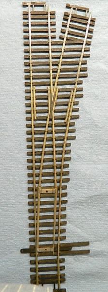
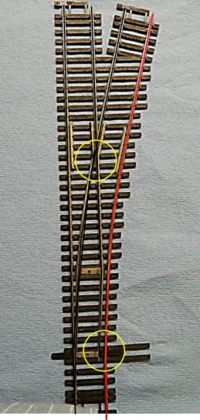
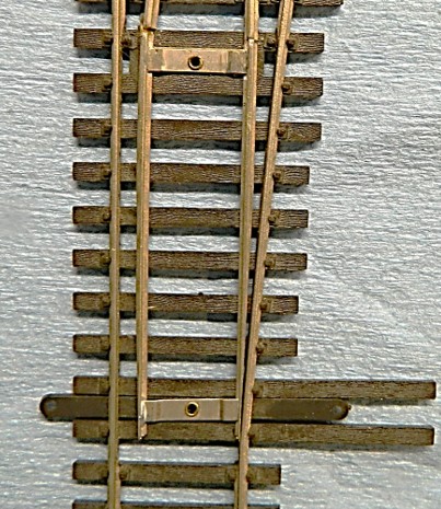
Couple of shots of what power routing is and what the pitfalls are for any point, DC or DCC.
Nigel
1. Shinohara code 70 turnout, HO scale, power routing design. Looks innocuous enough, but there be dragons! Note that double tie rod design. Those strips of metal are soldered to the rails and form a conductive rectangle. .
2. This is what happens when current is around. The left hand blade conducts electrickery to every rail except the right hand running track. Switch the points and the same happens in reverse. Peco is slightly better in that one side of the points and closures are insulated. The circles show the two problem areas for full and half power routing. A wheel touching both rails will short the circuit. These two areas are one the "devil is in the detail" issues when building turnouts. The other is making sure the closure rails run smoothly into the frog. Get the frog angle wrong by even less than a degree and it's derail time. I used to do this by hand, I now use a jig which does the frog and point blades to the required angle..
3. This why pins are not necessary.You can have fixed blades as long as there is wiggle at the junction of the point rails and closure rails. Shinohara used a belt and braces approach for their old code 70. Their new track uses rail joiners soldered to the closure rails and rigid blades. Works for me.
©Nigel C. Phillips
1 guest and 0 members have just viewed this.