SEEP motor point wiring for DC
Posted
#237074
(In Topic #13107)
Full Member
Need some advice for wiring SEEP motors to points for running on DC - seems to be much advice on connecting for DCC so wanted to check with those experienced on this club forum. I will be feeding the point switches and CDU's from a separate power supply to the track supply and I will be livening up the frogs directly so polarity switching will also be utilised via the SEEP.
Below is a typical setup that I can find plenty of on Google search, when I have crossed out the references to DCC and shown the connections to DC and track supply, which I believe I must have in order for the polarity switching to work. Is that correct?
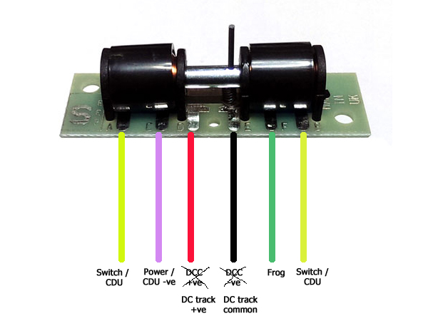
If that is all correct so far I understand I need to take the DC track +ve & common supply from the track supply feeding into the point - see example below. Will this be suitable feed connection for the SEEP motor point … even if the DC track feeds are not directly attached at the point?
As the layout is split into block sections, presumably when the block is isolated that includes this point I will only lose the effectiveness of the polarity as the point can still be thrown (in preparation for the next train movement operation once the section is made live again) as it has a separate power supply … is that also correct?
Thanks for any pointers to clarify.
Paul

Posted

Site staff
http://brian-lambert.co.uk/Electrical.html#Motor
near the bottom of the page
and yes, your last sentence, that too is OK for the wiring concept.
Ron
NCE DCC ; 00 scale UK outline.
NCE DCC ; 00 scale UK outline.
Posted

Full Member
The only thing different that I do is have track feeds directly to the stock (outside) rails of the point rather than relying on rail joiners to carry the current. My points are electrofrog, the one in the picture looks to be insulfrog.
This is just my personal preference and every single peice of track on my layout has its own feeder droppers for reliability.
Cheers
Marty
 Last edit: by Marty
Posted
Full Member
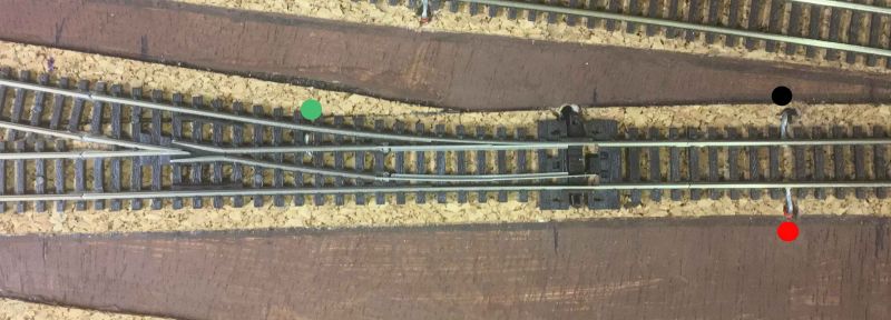
Hi Marty … also thanks for the confirmation. My points are all electro-frog and where you see the small green dot is where the dropper is soldered under the point ready to connect to the point motor. I understand your point about every piece of track having a drop feeder - does make sense however the rail joiners I used are pinched nice and tight and I have tested countless times so hopefully I will not have too many issues in the future … otherwise some adhoc soldering to the stock rail will be called for :-)
Thanks guys and have a great weekend
Paul
Posted
Full Member
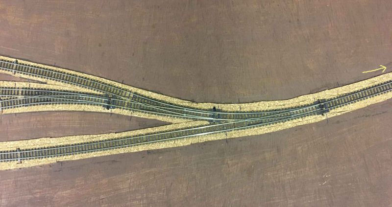
I have a section of points (below) that are all fed by track +ve & common supply coming from further along the track not in the photo - indicated by the yellow arrow. From an operational and the block section perspective I require this suits my needs but to feed these 3 point motors with track +ve & common supply for polarity it might appear as unnecessary extra lengths of wiring adding to complexity under the baseboard but wholly doable.
Are there any issues of polarity I might run into in feeding 3 point motors in this way if a loco were to run through all 3 points?
Thanks
Paul
Last edit: by Padster
Posted
Site staff
I will do a drawing and post it on here later on.
Ron
NCE DCC ; 00 scale UK outline.
NCE DCC ; 00 scale UK outline.
Posted
Site staff
I used your colours in the main
X1 & X2 are track sections switched on via the panel & I have assumed track 4 is part of a loop and that is why I have shown an insulated joiner near the frog of Turnout C. Also shown are Seep terminals CDE for the frog connections.
Terminals C on all Seeps is the same as X1 and you may wish to daisy chain terminals C back to X1 to save wiring to rail adjacent to Turnouts - your choice.
actual connections from rail to terminals C & D will depend on which way the Seep is fitted - may have to reverse wiring on C & D to overcome short circuits.

Ron
NCE DCC ; 00 scale UK outline.
NCE DCC ; 00 scale UK outline.
Posted
Full Member
I believe I understood correctly and as I like to picture this in my head quite literally in terms of my layout I produced the following interpretation. I adding in all the insulated joiners which suite my operational needs and are based on the design Trevor helped me with.

Following your explanation, I can daisy chain the red +ve from the SEEPs (broken red lines) for this section of points to the far right track feed (X1 on your diagram) … OR I can directly wire to the track at the entry of the points, following my early reference photo. All correct?
I assume I have no other choice and have to attach the black (common) direct to the track as indicated …. and also as you said, may have to reverse wire C & D as necessary as I see that my red and black track feeds in real life are opposite to your diagram.
regards
Paul
Posted
Site staff
And I have no problems being called Sol, that is my nickname used by my modeling mates here in South Australia
Ron
NCE DCC ; 00 scale UK outline.
NCE DCC ; 00 scale UK outline.
Posted
Full Member
I assume my suggestion of connecting the point motor to the track at the entry of the frog / point (even if its slightly on the previous piece of track to the point, as per my images) will be fine … and not as you drew it which I also assume was for clearer explanation purposes only and not to be taken literally?
Happy for anybody else to confirm that whilst Ron sleeps :-)
cheers
Paul
Posted

Inactive Member
Max
Port Elderley
Port Elderley
Posted

Full Member
Sol never sleeps . . . :shock:
 Too true !!
'Petermac
Posted
Full Member
Last week or two has seen some wiring activity, whereupon my good lady remarked that 'baby rainbow tentacled squid' had appeared in increasing numbers in the garage !!
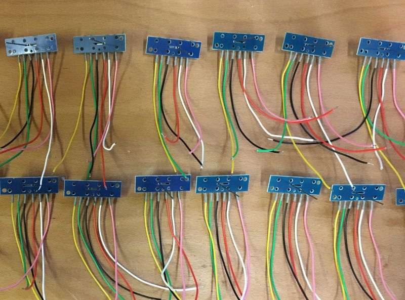
For somebody who had never soldered much at all previously, with a bit of practice with technique and watching some YouTube videos on the topic, I'm pretty pleased with the neat and increasing speed I can knock these SEEPS out including the heat-shrink. 17 down and tested, 3 to go … then the real fitting of the point motors and under baseboard wiring can begin.
cheers
Paul
Posted

Full Member
The output of your hard work mirrors exactly what I did when I built my last layout and used SEEPs for the turnouts. I know its a bit late but I found that having the "tails" all 12 inches long allowed me to wire them into a 6-way "choc-box". When the SEEP was installed, the choc-box was screwed to the underside of the baseboard and then all wiring went to that. Like you I used certain colours to do certain things.
Out of interest, can I throw in the issue of power loss for the SEEPs. They seem more susceptible (than, say, PECO standard point motors) to power loss caused by increased resistance in the connections/wires. I was using phono plugs to bridge baseboard joints and found them to be awful. The resistance they induced was enormous and the furthest SEEPs from the CDU were often reluctant to throw. I replaced the phonos with XLR plugs and sockets.
XLR's are used for carrying audio signals (X, Left and Right) and are designed to be extremely low resistance given that the microphones/instruments generating the signals have an output in millivolts. They are just as easy to solder, are more robust and although bulkier, do a wonderful job of baseboard bridging. I would imaging that computer cabling connections are similarly low resistance but my soldering skills and eyesight prevent me from trying to solder into a 20-pin connector!!!
I would agree with earlier comments regarding your wiring plan. I notice that you have soldered wires to bridge the stock rails and blades - I used to do this until I realised that I could feed the track using the same 2 wires so now make these my power connections and simply strip more plastic insulation off the wire and solder it to the turnout twice - once to the stock rail and once to the blade. Hope that makes sense.
I also tend to solder my track feeds to the fishplates rather than the rails - less obtrusive and (from my experience) just as efficient. Throughout the recent really hot weather (32deg in the UK is sooo weird!!) I did not suffer any problems despite the rail movements.
Barry
Shed dweller, Softie Southerner and Meglomaniac
Posted
Full Member
Actually I will be using choc blocks (connector blocks) fixed under the base board for each of the point motors for joining the wiring all neat, also allowing for the common feeds and looping feeds to run on to the next point, etc. Hopefully all will become clearer in my next set of photos once installed.
I will also be using the soldered track feeds into the points for power as you mentioned - in truth I already have various power feeds on the 'approaches' to the points, just not specifically right at the point entrance (as shown in an earlier photo). Those that I considered to be too far from the point I added new solder feeds - so a little mix and match but it will work ok and with not too many longer runs of wiring. I do have a few power feeds on the rail joiners but not that many … I personally like a solid solder joint wherever it can be achieved but as this was my very first layout I did take the simpler approach in a couple of places.
I do like the idea of the XLRs and will certainly look into those for the reasons you stated. I do actually plan to have 2 control panels that will manage each end of the layout. Each will have its own CDU to boost the point motors specific to each small yard - that way the CDUs will be close to the key motor points and not have long runs, thus reducing resistance and power loss … well thats the plan.
cheers
Paul
Posted
Full Member
Quick update on the SEEP and overall wiring install of the first module, finally putting into practice all that I have learnt based on the key advice from Trevor, not forgetting Sol too. Oh, and also the superb Brian Lambert website.
Its surprising how quickly the wiring can be done and how 'full' the baseboard undersides can become. I've been careful to document all the wiring diagrams / plans first to ensure I didn't go wrong (and also as key reference material for the future) plus clearly labelling all the key point motor feeds, block power feeds and common feeds as I went - especially important for making correct connections across the baseboards and to the control panels. I like to think I've done quite a neat job and easy for another pair of eyes to follow at anytime, especially with the aforementioned reference diagrams.
All droppers and point wiring is 16/02 and the main power blocks (x7 on this module) and common feed are 24/02.

What I did find was that over the counter/off the internet cable tidy clips are often harder plastic or not sized small enough for just a few 16/02 wires … so I cut down some 280mm x 5mm cable ties into 45mm lengths which are then perfectly flexible & sized to hold anywhere between 1-7 wires … tightening the screw to adjust to the required grip accordingly. Parts I used shown below.

cheers
Paul
Posted

Site staff
Ed
Posted
Full Member
Posted
Full Member
One the positive side for the first module wiring, all the SEEP switches work and all the block sections isolate correctly so I know my wiring is good.
Reference link to another post on my layout, where Trevor very kindly helped me.
http://yourmodelrailway.net/view_topic.php?id=15213&forum_id=6&page=3#p277947
Issue 1.
Ref image
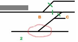
As you can see below, this point does not have IRJs at locations marked in yellow X, the power and common feeds are at the large red/black dots and the point motor feed to the frog is indicated with green dot. I have also show small red/black dots and connecting lines - these depict the point motor connections under the baseboard taking their polarity feed from the track main power / common feeds … I was assured this was ok to do.
Note: During this test, only this small section has power feeding to the track - nothing else on this baseboard module has a live 'red' power supply BUT the common 'black' is connected throughout.
Issue is, when the point is thrown as depicted below, the whole small section is shorted and the train does not move from its position left, off screen.
When the point is thrown the other way, the track is live and the train will move across the point to the lower right siding.
Looks to me that I do need IRJ at the yellow X positions as the live & common are shorting each other and as such the frog polarity switch will not work .. is that correct guys?
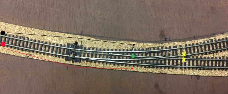
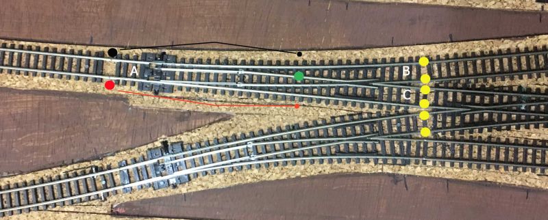
Issue 2.
Ref image

In contrast to the previous issue, this point does have IRJs at locations marked in yellow dots, the power and common feeds are at the large red/black dots and the point motor feed to the frog is again indicated with green dot. I have also show small red/black dots and connecting lines again for clarity.
Note: Again, during this test only this small section has power feeding to the track - nothing else on this baseboard module has a live 'red' power supply BUT the common 'black' is connected throughout.
Issue is, when the point is thrown as depicted below, the track is live and the train moves nicely from A to B.
When the point is thrown the other way, the whole section below and including the point is dead and the train will not move from A to C. (the letters A,B & C only refer to the image below … NOT the small ref image above)
This is more puzzling for me to solve immediately as the IRJs are in place so nothing should be shorting out, unless the wiring is faulty for the green frog feed, the point motor connection for the frog feed is faulty (both could mean the frog is left in a 'live' connection state) or I'm missing something obvious??
Sorry for the rather long thread but wanted to get all the information captured.
cheers
Paul
Posted
Full Member
I started checking all the obvious things first and all indications it must be the point motor wiring - and it was indeed the obvious, in that simply switching the red and black track feed wires (D & E connections on the point motor showed at the beginning of this thread) solved the problem - the train runs perfectly and the point motor feed and polarity work just as designed. Have now performed the same switch of feeds to the D & E connection on 4 points so far and all tested just fine.
All systems go now for the other 3 modules wiring.
cheers
Paul
1 guest and 0 members have just viewed this.