Sugar cane themed mini-layout
Posted

Site staff
On30 in a small space
[user=1632]BCDR[/user] wrote:


Posted
Site staff
Ed
Posted

Full Member
One of the things I am pondering. I would like 3 tracks running into the turntable, one out to the fiddle yard, so….
With a symmetrical three-way the length is 8.25"/21cm, if I used an asymmetrical #4 it would be about 14.5" /37cm. The issue with a symmetrical three-way is the requirement for double point blades, which means just the the rail web. With anything less than code 127 this is problematic. I did try it. The Peco symmetrical was in the spares box, their system of blade pressings works for a three way. I think it's one of the reasons why there are no other commercial offerings of a three-way. So I bashed a narrow gauge one. It may go on the fiddle yard, used in another modue, or stay in the spares box. Next step is to use some track and see what it looks like. I have that #4 wye that could be used instead. And a cunning plan for the turntable that will shave a few inches.
One other way is a three-day stub, I may have a go at one of those as the double point blades would be eliminated.
One of those cases where less may be better, and best determined before track meets glue. And avoid the consequential "Would you believe it!" And "What did you just say!"
Nigel
©Nigel C. Phillips
Posted
Full Member
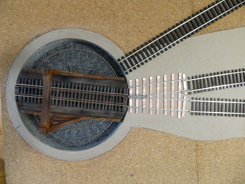
I now have the shortest turnout ever. After some pondering and commentary from Ed, I now have a shorty wye as the entry/exit for 2 tracks using the turntable, and room for a third track to one side. I suppose this is actually a stub wye, or almost a truncated crossover. I just need to add the guard rails. I saw some photos recently of a similar truncated crossover in 12' to the foot scale, used as a space saver for tight locations where the primary purpose was turning an engine. For those interested, Bembridge IoW. There will be buildings on one side of the turntable and a track on the other. Not really necessary of course, but I think it's an interesting detail. No throws, blades or tie bars required. That gives me the 3 tracks I was looking for. I can use the wye or the 3-way at the other end and still have around 3' of sidings.The wye works better, with a turnout immediately after on one side gives me the 3 tracks. Looks like the 3-way gets relegated to the fiddle/staging yard for the moment. It was fun doing the build. Ideal for 3 tracks.
I recycled the frog and closure rails from a Micro-Engineering #5 turnout, replaced the ties with copper clad to make it a wye, job done. I may redo with a #4 frog to give a better separation and an even shorter length. This is a 20 minute job, so maybe tonight.
I used some track I bought at a train show Saturday for the fiddle/staging yard to pose the picture. Code 100 Atlas HO at the top in black, approximately 24 feet of flex track for $6, around $0.75 per 3' section, brand new. It's for the fiddle/staging yard, no point in spending out on On30 track. It usually sells for $5 a 3' section. Lower 2 tracks are (expensive) Micro-Engineering code 83 HO track, I will use the rails for scratch building turnouts. Code 83 rail is expensive, comes from Micro-Engineering in packs of 32 (96 feet!). OK if you build a lot of turnouts. Cheaper for me to buy a section of track, which normally makes 2 turnouts.
Nigel
Edit 1. Forgot to mention, it is 4" long.
©Nigel C. Phillips
Posted
Site staff
Posted
Full Member
Thanks.
Well, I had a few minutes during the Premier League soccer half time this evening, so I got on with the MK-II version of the "shortest turnout". I had pre-cut the sleepers/ties earlier on, so this was just a soldering session.This one is more of a truncated crossover (scissors) like the one that was at Bembridge, just very slightly longer and a tad wider at the turntable end than the first one I built. Better separation of the tracks with that #4 frog though. All that is left to do is to cut some isolating gaps for the frog, and the isolating cuts on the sleepers/ties. I used the Fast Tracks $4 filing and soldering frog/blade jig ($$$, ouch, but it's good for a couple of hundred turnouts - as if!) and their #4 On30 wye template (free download), no guess work. Stock tracks through nicely, so job (almost) done!
I prefer the UK style fabricated frog to the frog casting beloved of North American railroads and model railroad track suppliers. The Micro-Engineering frog rails are also a bit skinny. Their frog seems to be a MAZAC/ZAMAC casting, so soldering is problematic unless I use the right Zn-rich solder and that witches brew of a flux.
This really is an easy turnout to bash or build, and a real space saver if you need a couple of tracks going to a turntable and space is tight. In N/HO/OO/O a wye cut down to the frog and a bit of the closure rails would work, eliminates the soldering. Two minutes with the Xurons and a file to conform the track to the turntable well curve. A regular turnout works as a donor, although the sleepers will be at a funny angle. In On30 it's a soldering job unless I use #5 left or right turnouts.
Nigel

©Nigel C. Phillips
Posted

Site staff
Ron
NCE DCC ; 00 scale UK outline.
NCE DCC ; 00 scale UK outline.
Posted
Full Member
Thanks. However, before anybody rushes in hold off until I do some calculations on the relationship between turntable radius and required frog angles. So obvious I missed it. :oops: :oops: :oops:
Nigel
©Nigel C. Phillips
Posted
Full Member
As I said in the previous post pretty obvious if I had thought about angles and not frog numbers. The frog angle for a realistic truncated scissors/crossover arrangement of two tracks depends of course on the radius of the turntable. In my case a #4 frog (around 14.2°)needs a radius of 4". Fine for 4-wheels wagons, not so good for my small locomotives of around 6.5". There is of course an inverse relationship between the frog angle and the radius. For my radius (3.6") the minimum frog is a #6 (around 9.5°, greater works fine). If anybody is interested I can draw up a table of radius vs frog angle or determine the equation. And there I was hoping for a greater track separation with a smaller frog angle. Fat chance. Looks like a bit more soldering tonight. I have a jig somewhere for #6 frogs.
Nigel
Note: My frog tables are in minutes and degrees, hence the approximate decimal.value. Anything between a #6 and a #7 will be fine.
©Nigel C. Phillips
Posted
Full Member
Interesting feature it could be, but I just looked at John Drew's last turntable post with interlaced track, good 'nuff says I. Just did a bit of measurement, only a tad wider than the frog version, not really enough to make any difference (0.1" with a #6 frog angle :roll:).. Interesting exercise though. Probably works better with a larger turntable.
Nigel
©Nigel C. Phillips
Posted
Full Member
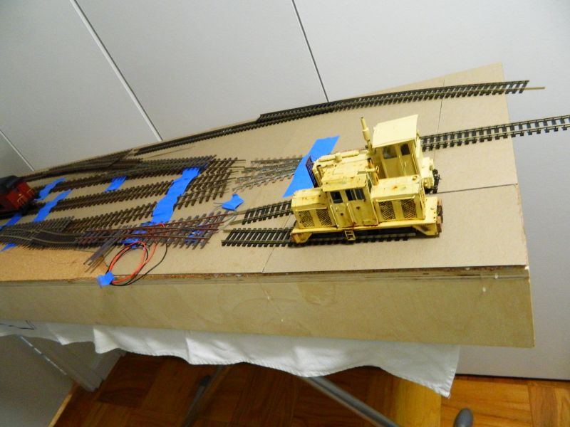
Underwiring/electrickery started, plus some track planning on the top. Seems I can use the 3-way and the wye after all.
Nigel
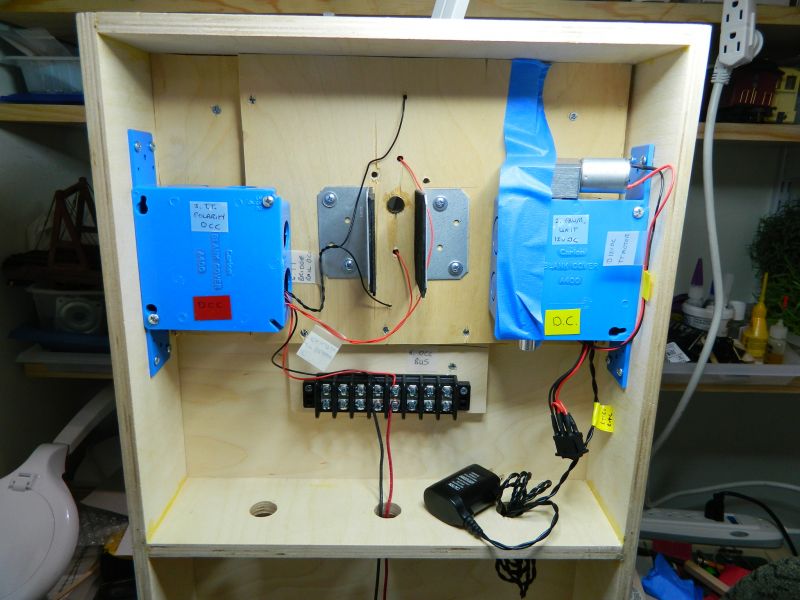
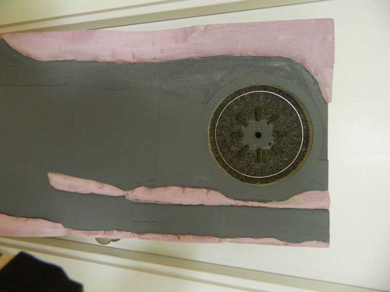
Turntable end. Left had side is the box for the polarity switcher for the bridge rails (Digitrax), middle upper is the feed to the bridge rails, middle lower is the DCC power bus (14 gauge solid copper and terminal block), right hand side is the box for the PWM circuit plus the 12v power supply (ex-electric razor, 12v/400 mA output). Hanging down is the rocker switch for the motor (forward/off/reverse). That will be put in the side wall. The turntable motor/gearbox is taped in place until assembly. There is a corresponding terminal block at the other end of the board. I tested the motor with the PWM controller, 0.6 RPM in both directions and no cogging.
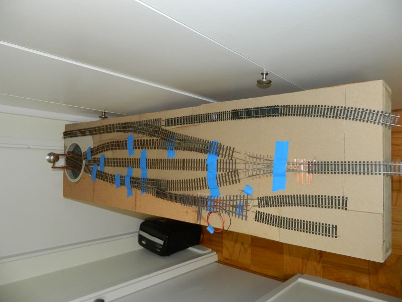
Track plan (subject to change depending on my mood, the weather and next doors cat). Three-way entry from fiddle yard with a head shunt for the locomotives, wye to engine shed, Mix of HO and On30 track until cutting time. Top/RHS track will pass behind the mill to the fiddle yard (which will be in the mill and may yet be a simple traverser). I may put a slight S in that one and get a bit more space for the workers halt and straighten the entry to the fiddle yard. All turnout switches are away from cross supports underneath. Long-term plan is for a scenic extension 5' long on the turntable end going to the sugar cane fields and equipment. Needs to be on an ascending gradient off the module.
Coal gondola (wagon) for the steam engines when being turned. Fuel oil for the diesels will be down by the engine shed.

Two road engine shed.(to be built). Basically a corrugated roof on rail supports. RHS will be the exterior wall of the mill.
©Nigel C. Phillips
Posted
Full Member
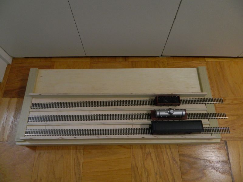
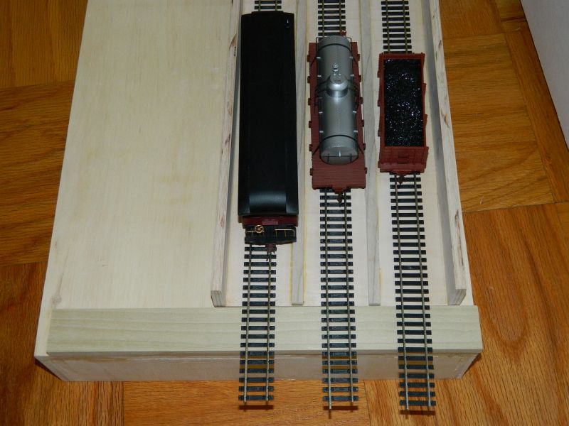
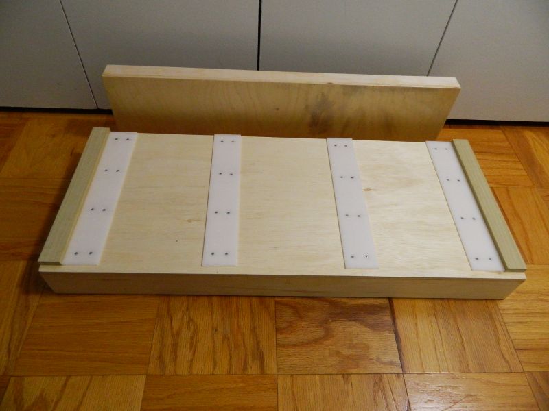
Time for a fiddle yard. Simple no frills project, plywood base and top, glue no screws, and a sliding "shelf' on top with 3 tracks that accesses 3 tracks on the scenic module. Each track will hold 4-5 freight cars and a locomotive, or 3 passenger cars and a locomotive. I am waiting for some 1/8" thick UHMW polyethylene strip to go on the top of the baseboard and the underneath of the "shelf". This is low friction high density plastic, and should allow effortless movement. I'm planning on keeping the electrics simple. More on that in the next few posts.
For those interested in this sort of thing: Base dimensions 3' x 15", "shelf dimensions 8.25" x 33", track is Atlas code 100 (brand new at $0.80 each at a recent show, retail is normally $5 each), plywood construction except for the poplar strips, base 0.5" 5 ply, shelf 0.375" 7 ply, 1.5" x 0.5' poplar strips at the ends of the board to locate the shelf and 0.375" x 0.5" poplar partitions on the shelf. All butt joint construction, interior grade yellow carpenters glue (I have found screws unnecessary for modules). Some varnish when the glue has had a week to really set. Time to build: 4 hours (including watching glue set).
The reason for the partitions is to allow for drop-in cassettes if I decide to go that route in the future. No plans on motorizing it at the moment, although If I find a suitable slim-line linear motor that may change.Ex inkjets are often suitable. Had to replace the ink in the current one yesterday: $75.00. New one with ink was on special for $45.00. May have a linear motor and carriage coming up when it's time for ink again.
Nigel

©Nigel C. Phillips
Posted
Full Member
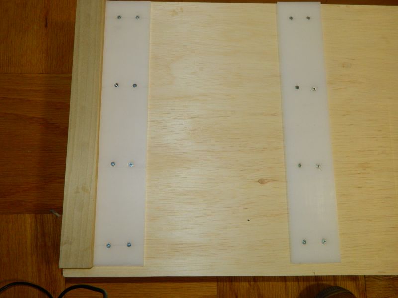
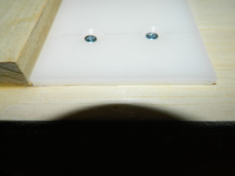
UHMW PE strip arrived, I fixed appropriately sized lengths in place using countersunk screws. Three coats of acrylic varnish were put on the base of the traverser. Glides across effortlessly.
Nigel
©Nigel C. Phillips
Posted
Full Member
Some more progress on the traverser. Track has been laid, no expense here, all of $1 a length, and all the storage tracks wired. Same for the 2 barrier tracks between the storage tracks and the scenic layout board. The plan is that both will be wired to the bus system, on-off switches to control whether they are live or not. That way there is no risk of a short when the traverser is moved from one access track to the other, and power can be maintained on the traverser (or not if stock is being changed). The traverser will have a 2 amp RCA-type jack and flexible cable to allow it to be disconnected from the on-off switch. More on that part of the wiring shortly.
There has also been more progress on the scenic board, I now have some 3D topography thanks to HD closed cell foam and the foam cutter. I come out in a rash with this material, gloves on until it's painted. Fixed in place with "Liquid Nails". Not completed, photos in the next installment. I used an electrical (heat) foam cutter, that will prevent the cries of "where did this pink dust come from?". And the bread knife stays sharp of course. Most of use have probably bin there, dun that. Once.
Nigel
Photo 1. The traverser on the frame. Track is laid on cork painted grey. The adhesive was PVA white glue. Track stays in place under normal use, peels off if required.
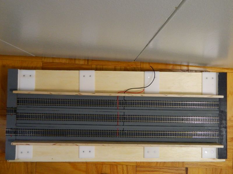
Photo 2. Track wiring, traverser. The wires to the left will be anchored on the outside frame, and connected to the RCA jack.
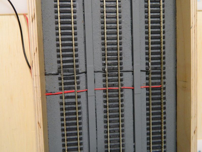
Photo 3. Track wiring, barrier. Directly down to the terminal block.The wiring is 22 gauge solid copper, ready tinned for soldering.Easy to work with.

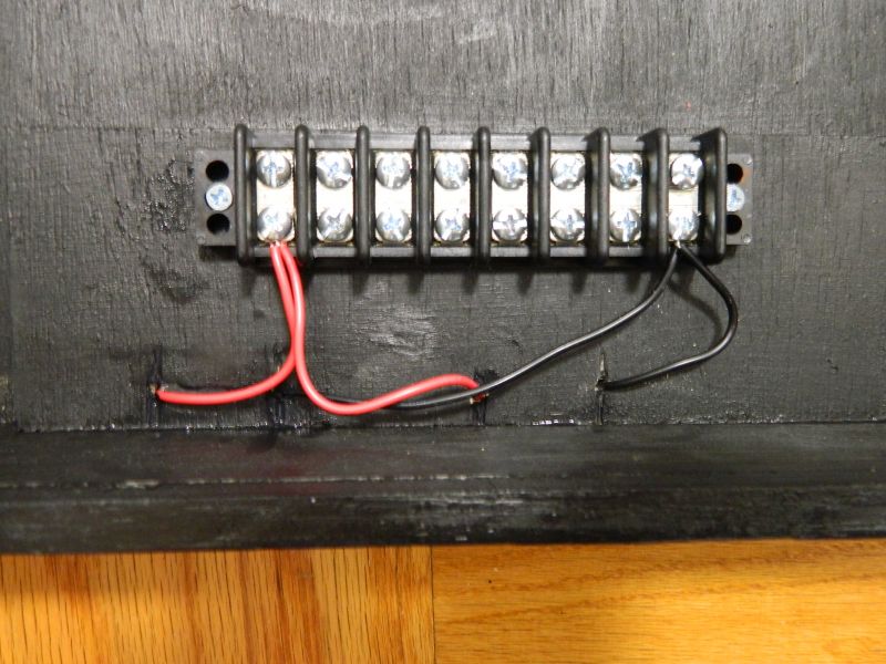
Photo 4. Both barrier tracks wired to the block. I had a box of these in the spares drawer, 30 amp rating, so probably adequate for my NCE system. Should be enough slots for wiring the bus from the scenic module (30 amp power-poles), and the on-off switches. These are rated at 5 amp. I was going to use sliders, but most are rated at 0.5 amp or less, so regular toggles. Belt and braces approach, given that the maximum power draw will be around 1.5 amp.
©Nigel C. Phillips
Posted
Full Member
Posted
Full Member
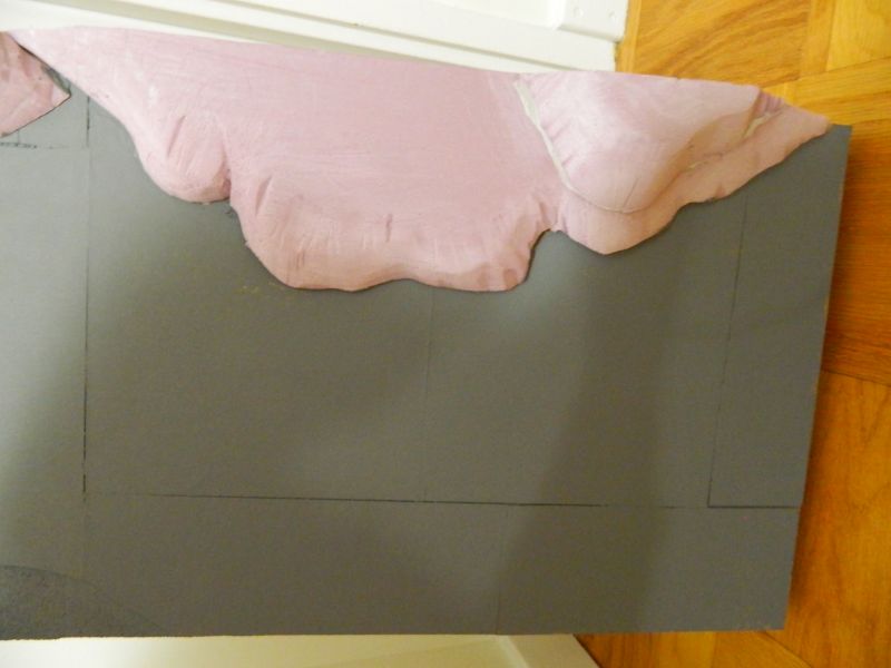
Some photos of the scenic board ready for track laying and wiring. Still having problems with my new picture editor.
The incline to the right of the turntable is 2.5% made with some cedar shims (they come with this slope
 ), and will be the resting place for some time-expired rolling stock. Remember that 3D print loco body shell? :roll: I was going to extend the layout with another board, common sense kicked in, as in where am I going to store it? New modeling interest on the horizon, so the aim is get this one up and running and play trains ("at last!", I hear them cry, plus a few jeers of "about time too!" Along with a few mutterings of "well I never" and "I don't believe it").
The pink material is the HD closed cell foam, shaped with the foam cutter and dressed with #150 grit. I'll carve some rocks later using the needle tip on the soldering iron at the lowest temperature (either coral limestone or volcanic basalt, the yard was built in an old quarry, and the is;and has a volcano). Top surface for the track area is cork with an additional 0.5mm thickness of card stock.
Nigel
©Nigel C. Phillips
Posted
Site staff
the pink foam would be far lighter in weight than plaster etc
Ron
NCE DCC ; 00 scale UK outline.
NCE DCC ; 00 scale UK outline.
Posted
Full Member
So does mine, but there is a glitch in the software. I will have to switch to a different one.
Scenic stuff directly on the foam, plaster cloth not necessary. What helps is having an electric foam cutter, gets the shape desired. No crumbs everywhere.
Nigel
©Nigel C. Phillips
Posted
Full Member
It has been some time since I last posted (Jan 20th in fact), life events kept getting in the way throughout the first 3 months of the year. Back to getting some things done on the sugar mill mini layout, so here is an update.
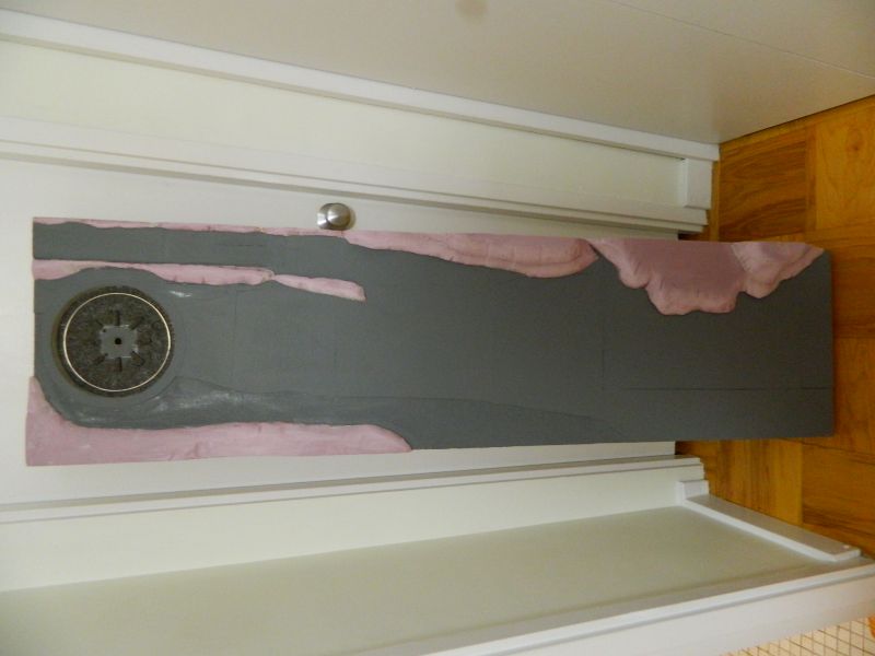
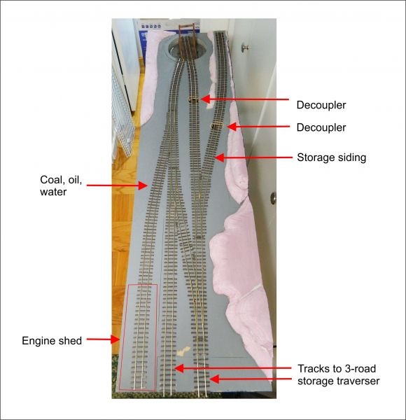
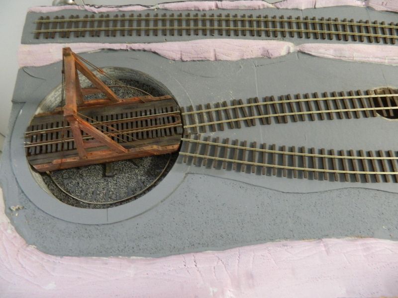
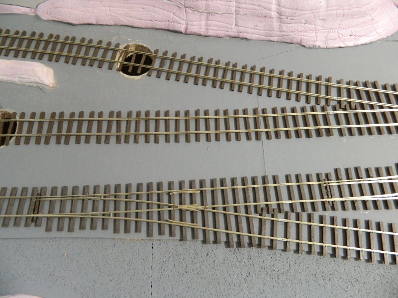
1. Track plan rationalized to 4 turnouts, 2 access tracks, engine shed track, a storage track on a 5% gradients that will have some dead stock at the far end, and the turntable. I may add one more turnout, still thinking about it. Although it would be nice to have a small passenger halt. I have some On30 passenger cars just asking to be cut and shut. Decisions, decisions. All turnouts are Micro Engineering On30 #5 frogs, track is On30 from the same supplier. The crossover was soldered up as one unit and droppers were installed before laying on the track. The turnouts come DCC ready. It is not necessary to wire the isolated (but "live") frogs, they are less than an inch long (2.5 cm) and anything bigger than an 0-2-0 trundles across without any fuss. All the diesels are Bo-Bo with all-wheel pick-up, so no problems there.The Forney 0-6-4 based on the Godchaux, LA, sugar plantation locomotives will also have all wheels live.
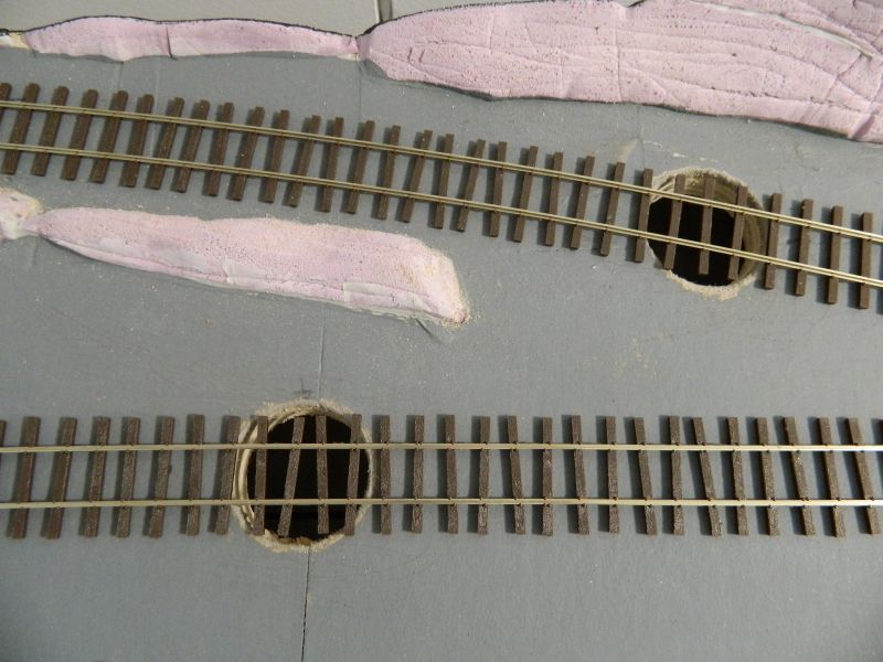
2. Two Rapido Trains electromagnet decoupler units were found in one of the storage boxes. "Why not?" I thought. So a couple of holes 1.75" (4.45cm) in diameter were drilled to accommodate them. More on these units as they get installed. They come with a pre-wired toggle switch, connectors, LED indicator light, switch panel, screws and washers, and a plastic cover for the ballast. Neat approach, and takes up about the same space as a KaDee under-track magnet. They can be retro-fitted if necessary.
3. A more powerful DC supply is now required. I will be swapping the 12V, 400mA unit for a 12V, 1.25A one that was also lurking in the storage box. Stabilized output as well. I will be putting in a DC bus, as well as installing the toggle switches for the decouplers.
4. I was going to install an NCE circuit breaker (light bulb design, 6 power sectors), but the DCC Specialties PSX ones looked better, can be used with the NCE power Cab, and have a DCC address, so I ordered one. Should be here next week. More on that when it arrives and is installed and why a circuit breaker is an absolute necessity for the NCE Power Cab. It will mean a small change in the DCC bus wiring.
5. Droppers are being installed this week using solid core copper wires, and the track tested (and retested) before fixing in place with PVA. And then tested again.
6. The tracks to the storage traverser will go through the sugar mill. Which will be the scenic break. The "engine shed" will be no more than a corrugated roof lean-to with old rail supports. The idea is to stagger the mill back going from left to right so that there are sight-lines to the traverser unit. Hopefully that will work out.
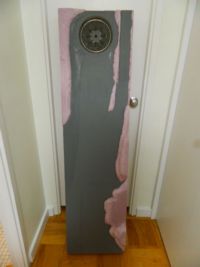
Photos of the final track plan below. The scenic part is just over 5 feet long (155cm) and 15" wide (38cm). The pink pieces are HD closed cell foam embankments on top of which some sugar cane plants will go.
Nigel
©Nigel C. Phillips
Posted

Inactive Member
I like the randomly offset ties - typical of our sugar cane railways in Oz - Queensland.
Cheers
Max
Port Elderley
Port Elderley
1 guest and 0 members have just viewed this.