GWR 57XX in 7mm. This IS the very last kit build.....
Posted
#235616
(In Topic #12986)

Full Member
from a JLTRT kit purchased 6mths before their demise.......
OK, I`m going to build a riveted tank version based on a 1930`s batch built by Kerr,Stuart and Co numbered 7700-7724 that were vacuum brake fitted so can be used on passenger duties. ( those numbered 6700-6724 built at W G Bagnall were not vacuum fitted and were for shunting only).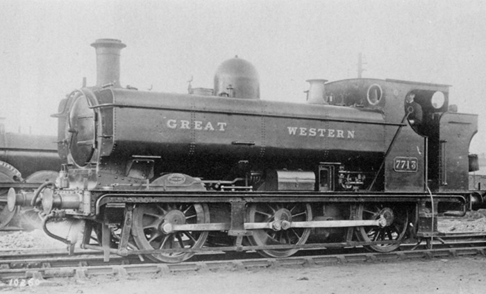
This above is what I`m aiming for……………………………………………………………………………………………..
The kit is very well designed and has been around for some time (until recently with the sudden demise of JTLRT)
Yes I know there are 7mm RTR versions on the market from Minerva and Dapol, but I have a strong preference for
handbuilt versions with my own choices of compromises rather than theirs.
The kit relies on very good diagramatical instructions with next to no written description, so not for the absolute novice.
As always I choose to build a reliable working chassis mechanism first……. I am and always have been a follower of sprung hornblocks for all locomotive chassis ever since my 4mm P4 modelling days as this method provides the best way of maintaining electrical pickup from track to wheels and I believe adds to the smoothness and realism of locomotive performance, particularly as I am a strong convert to DCC Sound where good electrical conductivity is paramount.
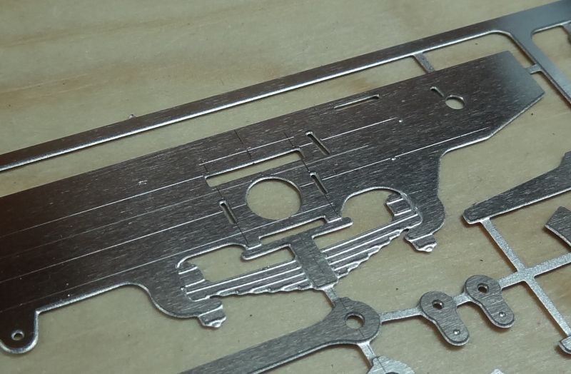
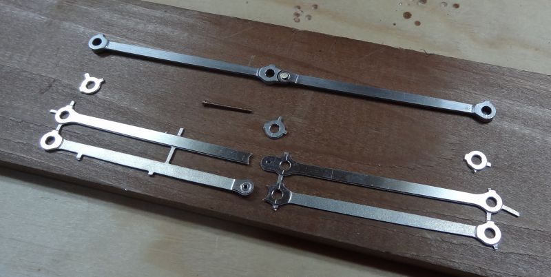
Whilst researching other modellers effortswith this particular kit, I noted the accuracy of the nickel silver chassis side frames when using the lost-wax cast hornguides and bearings supplied with the kit. However, despite other modellers sucesses, Ifound the hornguides and bearings in my kit had far too much slop in both the axle bearing and the bearing and hornguide……….
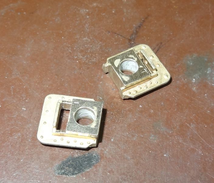
So,as a first, I substituted the lot for a set of sprung hornblocks from Slaters as minimising axle slop fore and aft is essential for preventing wheel/coupling rod binding in the longer term. The last thing I want is to have to dismantle a chassis and start again.
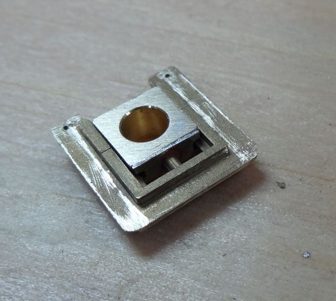
As you can see, Slaters hornguides and bearings are a more accurate offering with absolute minimal fettling required.
There is an added bonus of a cast in axle centering guide on each hornguide which can be lined up with your chosen scribed axle centre line on the chassis side frames……….
So, armed with a better quality set of hornguides, the next task is to mark up the chassis side frames in order to cut out the hornguide slots and position the whereabouts of the axle centre line.
Now…… this is where a better kit is helpfull in providing etched in `dimples` for both the brake hangers and axle centre lines.
It is important when using replacement hornblocks that they fit into the kit`s etched axle positions to avoid problems further on when the wheel splashers are fitted.
Having done all that, I carefully drilled the coupling rod etches to take Slaters crankpins and also drilled the holes to take Slaters sprung pickups.
Now…………..
………………….annoyingly there is a plastic pyramid `tie` that encroaches into the wheel rim which if ignored can cause a break in electrical pickup on every wheel, so to avoid this I made sure that the pickup plunger hole is in such a position to avoid contact with this plastic pyramid…….
Cutting out the hornblock positions was simple enough using a slitting disc…….
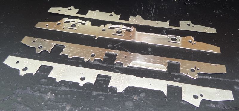
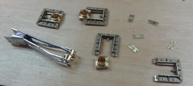
The kit comes with a lost wax detailing upgrade pack so I removed the etched spring hangers to be replaced with lost wax parts.
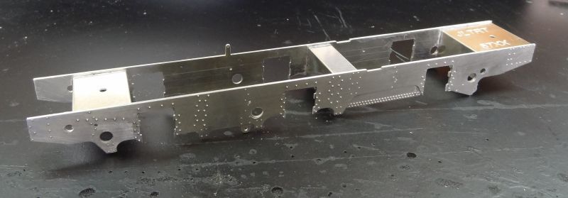
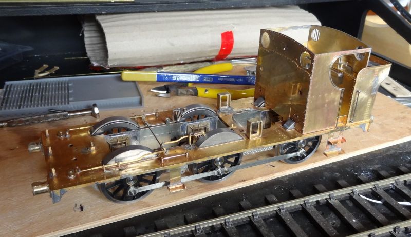
The end result is a strong chassis sub-frame using the fold up spacers provided that are an accurate slot and tab assembly. I particularly like the etched riveted overlays.
Next is to turn the etched coupling rod overlays into working centr hinged coupling rods……..
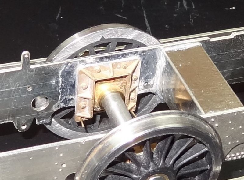
Then…. its over to an old favourite,simple and reliable method of setting up the hornblocks using the coupling rods as jigs……..
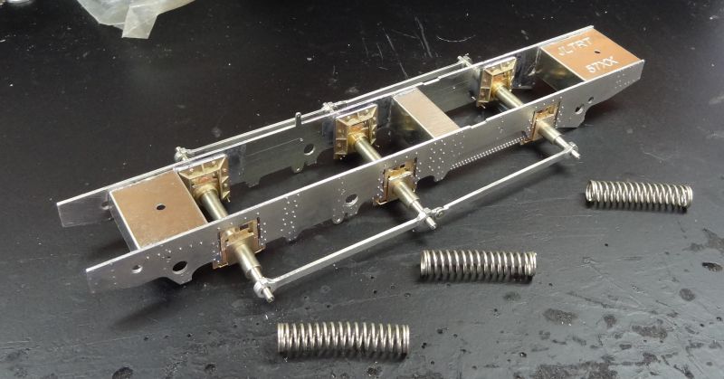
……obviously the springs are used to hold the hornblocks hard up against the sideframes prior to soldering onto their final positions , making sure the axles are at right angles to the frames.
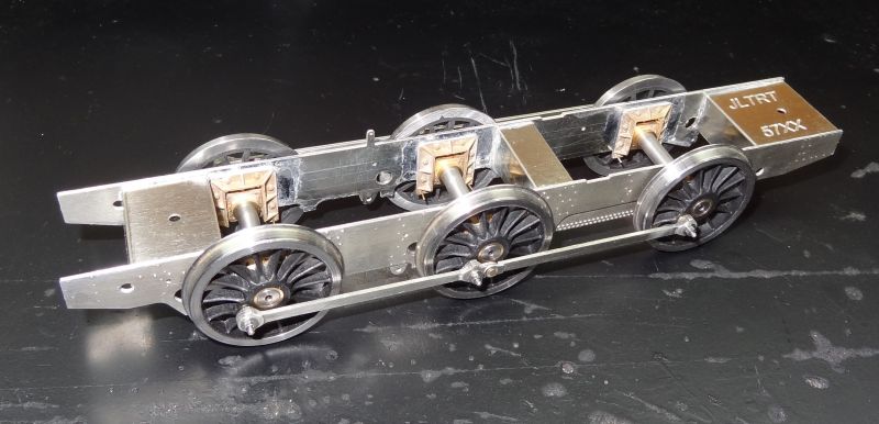
….the end result is a very free running assembly every time………………………….
Twobolt John

Posted

Full Member
You’ve made a cracking start with those Slaters' hornblock assemblies and the rolling chassis looks as good as it so obviously moves.
Crack on!
Best,
Bill
At 6'4'', Bill is a tall chap, then again, when horizontal he is rather long and people often used to trip over him! . . . and so a nickname was born :)
Posted
Full Member
not `probably` but definitely as the eyesight has got to be looked after. I agree about the iconic GWR Pannier and she will go with my completed GWR Castle and GWR Autotank.
Cheers
John
Twobolt John
Posted

Full Member
How long will she take to build?
Oh, Dr Beeching what have you done?
There once were lots of trains to catch, but soon there will be none.
I'll have to buy a bike, 'cos I can't afford a car.
Oh, Dr Beeching what a naughty man you are!
There once were lots of trains to catch, but soon there will be none.
I'll have to buy a bike, 'cos I can't afford a car.
Oh, Dr Beeching what a naughty man you are!
Posted
Full Member
John
Twobolt John
Posted
Full Member

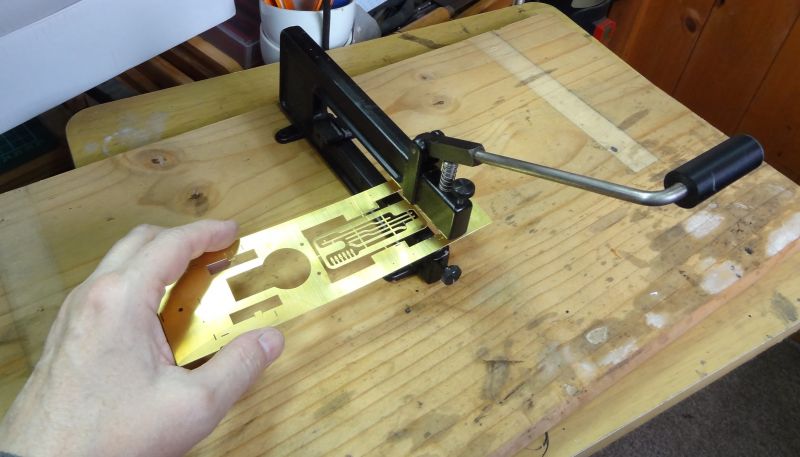
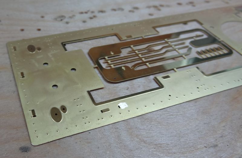
The etched footplate is soldered onto a very cleverly designed footplate sub unit to keep everything square as you proceed.

There is some pre etched rivets to be formed on the reverse of the footplate overlay.
All my GWR locos have lost wax lamp irons so the next move was to carefully remove the fold up etched ones and replace them with the lost wax versions supplied with the kit.
To my eye these look a lot more realistic…………………………………………………………………………………………………..

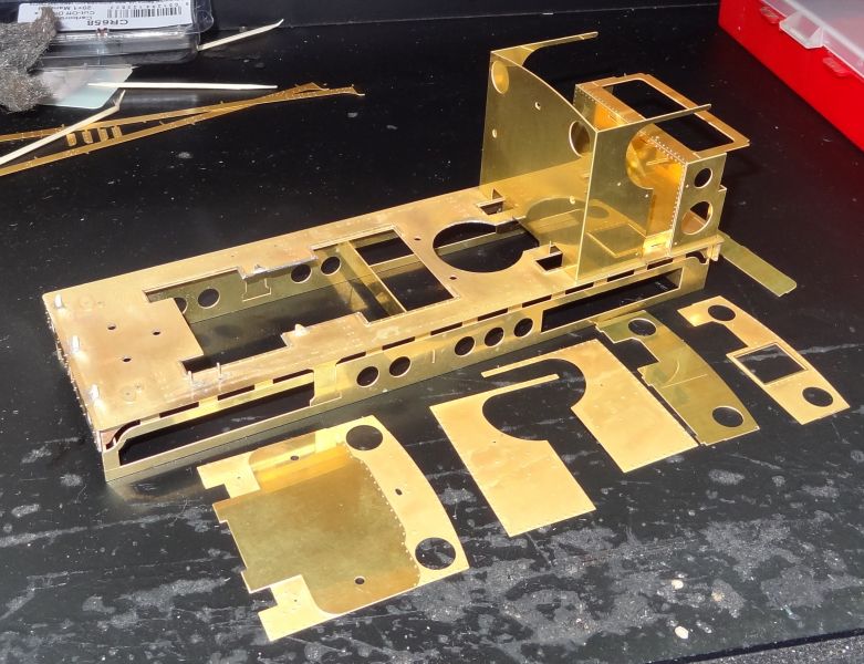
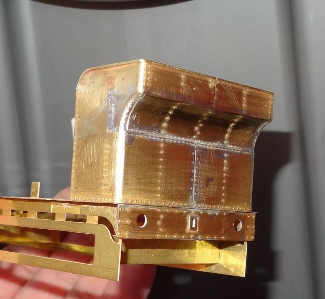
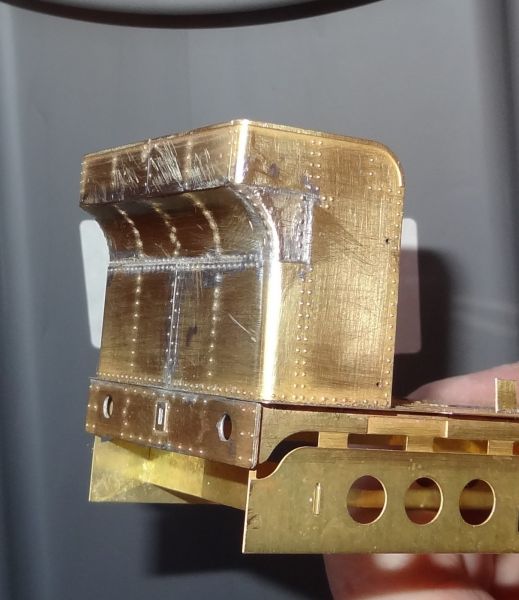
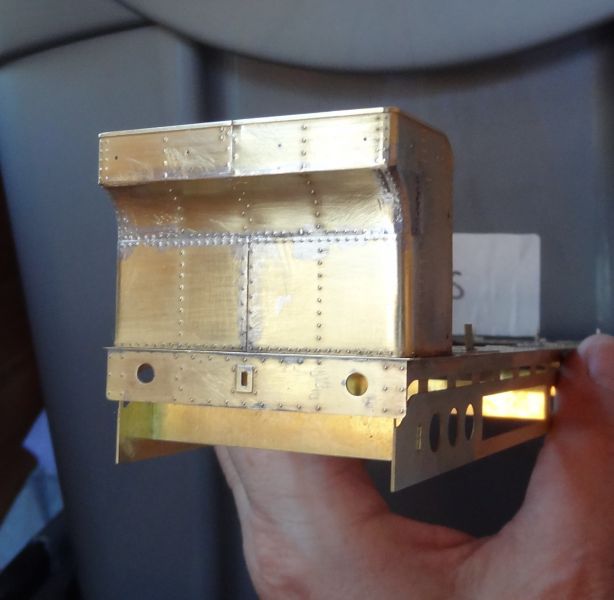
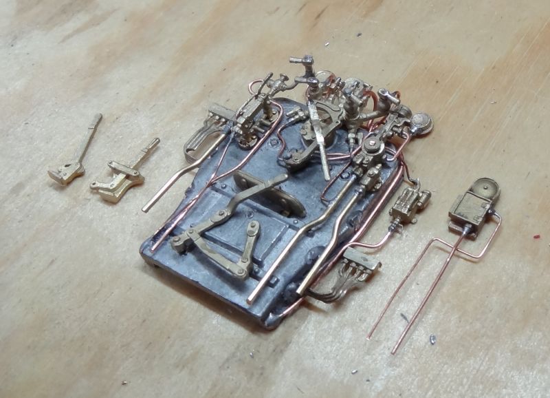
The cab and bunker is made from three fold up sub-units onto which has to be sweated some detailed overlays.
My 80watt iron was not up to the job so I used a flame heat source which was much easier.
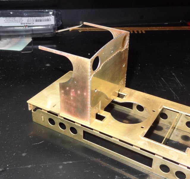
There are some lost wax parts that also need to be soldered to the sub units before final assembly.

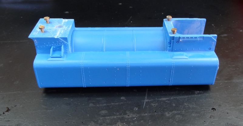
And then comes the already notorious making of the JLTRT Pannier tank bunker !!! the two bunker corner castings bottom right above are not quite the right size to fit well on the bunker corners and the quality of the castings on mine were not brilliant.
First up is shaping the bunker overlays………………………………………
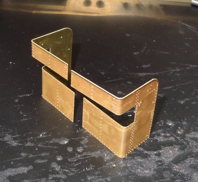
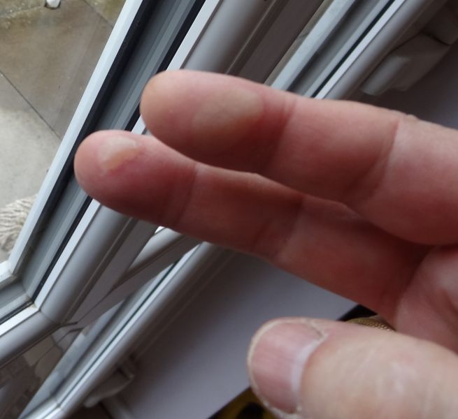
Then attaching them to the bunker sub unit…… much finger burning and singing happy songs not!!!

finally …. this is the best I could do at soldering it all together……………………………………………..
Twobolt John
Posted

Full Member
I'm in the process of restoring a Gaiety JVM 5700 family heirloom, so it's interesting to see what one 'should' look like!
Keep up the good work,
Gordon
Posted

Full Member
The bigger it gets the more it seems like brazing. It's how the Koreans did it - tin the parts, clamp together and out with the hand pumped torch. I think I would be tempted to get a big resistance soldering unit.
Looking good though, toasted pinkies excepted.
Nigel
©Nigel C. Phillips
Posted
Full Member
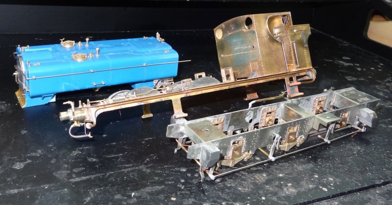
There were a few things to modify as I went along, but the chassis matched up rather well to the footplate
My preferred method with handrails is to build in two halves

…………… and join with solder at the front handrail knob……………………………………….
I also prefer to complete all of the chassis structure and make wheels removable for painting etc
Beginning to look like a pannier tank engine
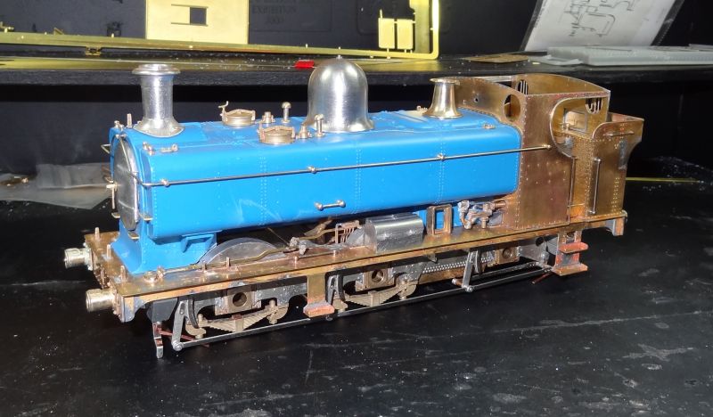
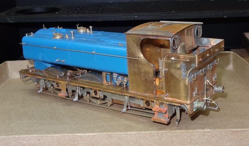
I`ve built the whole project in three parts to help with painting
The cab backplate I modelled on the preserved No 7714
 Last edit: by Twobolt
Twobolt John
Posted
Legacy Member
reg
Posted
Full Member
Is the blue blob already done?
Nigel
©Nigel C. Phillips
Posted
Full Member
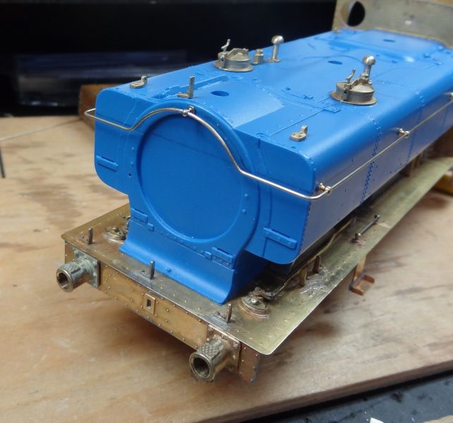
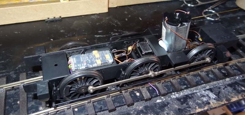
Yes the blue resin moulding is part of the kit and just needs drilling and tapping to fit on the footplate and details added to it.
Which is fine and helpfull unless like me you want to fit a speaker and decoder………
I had to resort to fitting them all between the frames……………………………………

Cheers
John
Twobolt John
Posted
Full Member
Not "just like the real thing" then. Was this ever designed for DCC sound? And here I was thinking you would have room for a decent bass/crossover/tweeter with steam sound coming out the front end and whistles out of the cab area. What about the bunker for the decoder? (And even the speaker). Or even drilling/milling out some space in the boiler/side tanks for the decoder? I gather you are not doing valve gear with the decoder positioned there.
Nigel
©Nigel C. Phillips
Posted
Full Member
And the bunker cast corners are a difficult pig!!!
I knew from others that the bunker has little suitable space for a decoder, but possibly a speaker : but then you`ve got the bother of having to drill through thick gauge material on the footplate and again through the rear chassis spacer to feed the wiring through……. nah!!!.
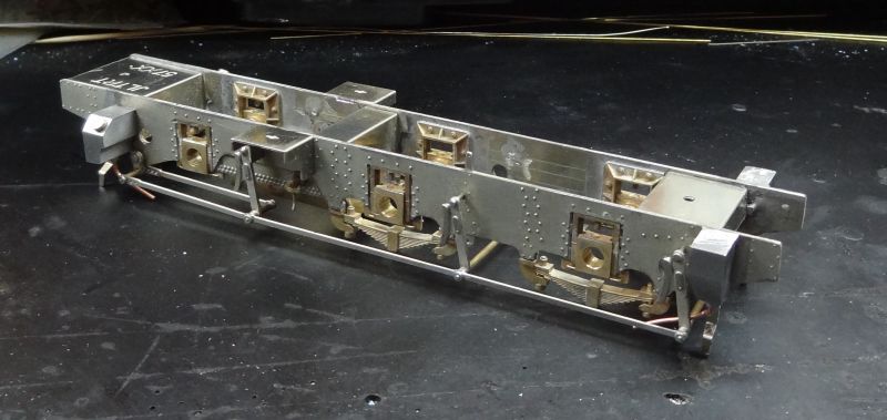
I made the right decision for me to have all the DCC stuff between the frames……

…………………. and when all is painted black ( a Zimo decoder has a thick protective cover) it`s not noticeable at normal viewing distance.
I`ve never been impressed with inside valve gear ( unless you make locos for the display cabinet) as on a working layout at normal viewing distance you can`t see it anyway. I prefer working models that are easy to service and maintain. It`s a lot of extra work for little reward and over half of locos that I have seen modelled with it run badly as a result of it…….to my eye…..
Overall I like the look of the finished kit and is good value for money for what is included ( £255) less wheels and motor of course). But it is`nt as good as an MOK kit.
Wait till you hear Digitrains Pannier tank sound !!!!
Cheers
John
Last edit: by Twobolt
Twobolt John
Posted
Full Member
Those curves are tough to do, anytime I have done one (in HO or 4mm) I have two different models, depending on which side you looking at.
Interesting approach though. It must help with the mass. Your comment on the thickness of metal and the less than perfect fit of the bunker bits was interesting. The thicker the metal the more difficult it is to get precise etching. Easier to cast in resin or decent white metal.
The model is really starting to look the business.
Nigel
©Nigel C. Phillips
Posted

Full Member
Posted
Full Member
However, just a brief update as No 7714 is virtually out of the main paint shop……………………….

…………..still a few details to add to the superstructure and then the fully detailed cab and roof………..
so, will be finally finished at the end of this week……………………………………………………………………………
Not a Bob John
Twobolt John
Posted
Full Member
Not sure how Bob came into the picture. Mind you, I'm sure he would appreciate the work you have done.
Nigel
©Nigel C. Phillips
Posted

Full Member
I know I have neither the skill nor the patience to undertake such a task so I am in absolute awe. The end product is magnificent and the "write-up" equally superb - very well done Sir !!!
'Petermac
Posted
Full Member
Best,
Bill
At 6'4'', Bill is a tall chap, then again, when horizontal he is rather long and people often used to trip over him! . . . and so a nickname was born :)
1 guest and 0 members have just viewed this.