Track power connections across baseboard modules
Posted

Full Member
Best wishes Kevin
Staying on the thread Kevin.

Posted

Site staff
Hijacked Paul's thread yet again :sad:
Ed
 Last edit: by Ed
Posted

Full Member
My apologies. Offending posts deleted.
Nigel
©Nigel C. Phillips
Posted
Full Member
http://yourmodelrailway.net/view_topic.php?id=15440&forum_id=6&page=2#p282280
.. are causing me issues as the shortest cable lengths I could acquire were 1 metre lengths. These breakout terminals and cables are being used to connect the point wiring (and CDU feed) across 2 4 foot layout modules but as I'm using 16/02 wiring for all the point wiring runs and with these 1 metre length DB15 cables, I'm afraid i'm losing voltage to drive the 5 individual points on the connecting module - the other module that hosts the CDU works perfectly for 3 individual points on that module.
To test connectivity, I have bypassed the DB15 breakout terminals and DB15 cables temporarily by connecting one of the point feeds and CDU feed directly across the modules using choc blocks and hey presto, power voltage more than adequate to drive the point.
So .. I'd rather not waste the DB15 breakout terminals so perhaps I'll try and cut / shut the DB15 cable to make it much shorter (which not looking like an easy option) or bite the bullet and ditch the DB15 idea completely and install more connecting choc blocks …. best laid plans :-(
Posted
Full Member
I've ordered some DB15 socket / plug connectors from Railway Scenics and will solder in my own 16/02 wire to make a short cable … which I am hopeful will do the trick.
If this fails (which I cannot see why it would) then my last option is connecting choc blocks .. will keep you posted.
In the meantime the second control panel is now being wired up … photos of everything so far to follow.
Paul
Posted

Full Member
I haven't totted it up but wonder if it might have been a better option to have each board free standing - i.e. independently wired from it's neighbour and each with it's own CDU. That way, you could have used simple banana plugs to power up your main bus wires board to board and have everything on each board wired off those buses ………………… :hmm
'Petermac
Posted
Full Member
I am with Peter on this one and if you look back on the thread I suggested RCA plugs and sockets which you can use with heavier wire and they should take a lot of "punishment" over a time. You will need 8 Jumpers each between modules 1 and 2 and modules 3 and 4 and 4 jumpers between modules 2 and 3.
An advantage would also be that you could use thicker wire and voltage drop would be a lot less from your two control points.
I can do an illustration but will be away till tomorrow night unless I can sneak in a few minutes tonight if you feel the need … Bus wiring is straight forward because it is straight through connections which in my field we actually called "train lining" but like a lot of wiring work, it is simply slog…
Hope this helps,
Regards
Trevor
Last edit: by xdford
Posted
Full Member
Thank you but no need for an illustration … I did a reply a few mins ago but the posting failed and I lost my text completely :-( … I'll write it out again tomorrow.
Also Peter … the cost of the DB15 connectors and cables were not that expensive … slow boat from China as I was in no rush :-)
More tomorrow
Paul
Posted
Full Member
Call it a Senior Moment… I was actually reading a news bit about Kevin Rudd about 2 minutes before I saw your post!!
Sorry Mate,
Regards
John Peter Trevor
Posted
Full Member
For clarity I have been following Trevor's excellent advice on the electrics throughout my build so far and did consider using RCA or banana plugs - but I'm not sure it would have worked out any cheaper or simpler really. As mentioned, the DB15 terminal breakouts & cables came from China and were pretty cheap if not the fastest of delivery.
To be clear, I have my 24/02 wired power connections for the isolating blocks successfully connected and working with perfect power across (as per Trevors design) so all good there. Where I DO have a problem currently is the point wiring (7 points on the 2 modules I'm connecting currently) which is using 16/02 wiring throughout and each module feeds into the DB15 terminal breakouts which can handle 10 amps - example below

I've testing and looped a couple of these physically with 16/02 wiring from breakout terminal 1 to breakout terminal 2 (across baseboard modules) thereby bypassing the DB15 cable … and the points work ok from the East end control panel. As such, the conclusion is the 1m cable is too long and also the small core wire within it is simply not up to the job to transferring and retain the voltage (perhaps tha is why there were cheaper !!). I now have 'virgin' DB15 (DSUB) male and female cable connector ends (75p each from railwayscenics) and will carefully solder 16/02 wiring and make my own cable … which I'm certain will then work .. also meaning everything you see in the photo remains intact and not wasted - and hopefully still very neat.
Naturally, the soldering will have to be done carefully and be a little fiddly but I think I'm up to it :-) .. otherwise there is a soldering demonstration and tips stall at the Chiltern Model Railing Exhibition this weekend Chiltern Model Railway Exhibition 2021 where I can get some extra tips.
Hope this explains better what I'm trying to achieve and that the cost overall has not been excessive at all … after all there are many ways to connect baseboards :-)
and Trevor, no probs with calling me Kevin … I also have senior moments myself for sure :-)
cheers
Paul
Posted
Full Member
I should B. hope not. Best wishes KevinHi Trevor …. I am Paul, not Kevin … seems you called me this before in this thread for some reason.?
Thank you but no need for an illustration … I did a reply a few mins ago but the posting failed and I lost my text completely :-( … I'll write it out again tomorrow.
Also Peter … the cost of the DB15 connectors and cables were not that expensive … slow boat from China as I was in no rush :-)
More tomorrow
Paul
Staying on the thread Kevin.
Posted
Full Member
In summary, all the electrics are finished and with all modules connected and in place, testing completed 100% successful - I'm very happy and pretty chuffed - all the steady progress and checks / double checks paid off.
I'll continue my updates now on my main Braughing to Standon Branch thread from now on but for completeness on this particular thread (Track power connections across baseboards) and the under baseboard electrics, I'd like to share photos I took throughout which hopefully will be of use to somebody else starting out and give some ideas.A few photos I may have shared on other threads so apologies in advance for any occasional duplication.
The SEEP solenoids and power power drops being positioned - all 16/02 wiring.
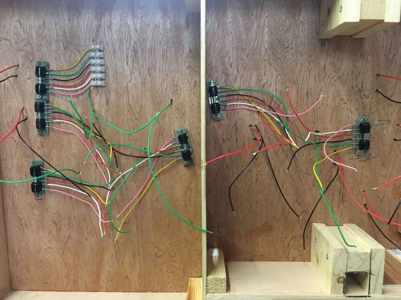
SEEPs and main track power wiring being installed - track power main bus wires all 24/02. Also labelling of all point SEEPS, drop power wiring, track wiring, point polarity wiring (green) undertaken. These are all transferred onto drawn diagrams for accurate reference for any future troubleshooting … or handing down to my son :-)

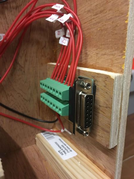
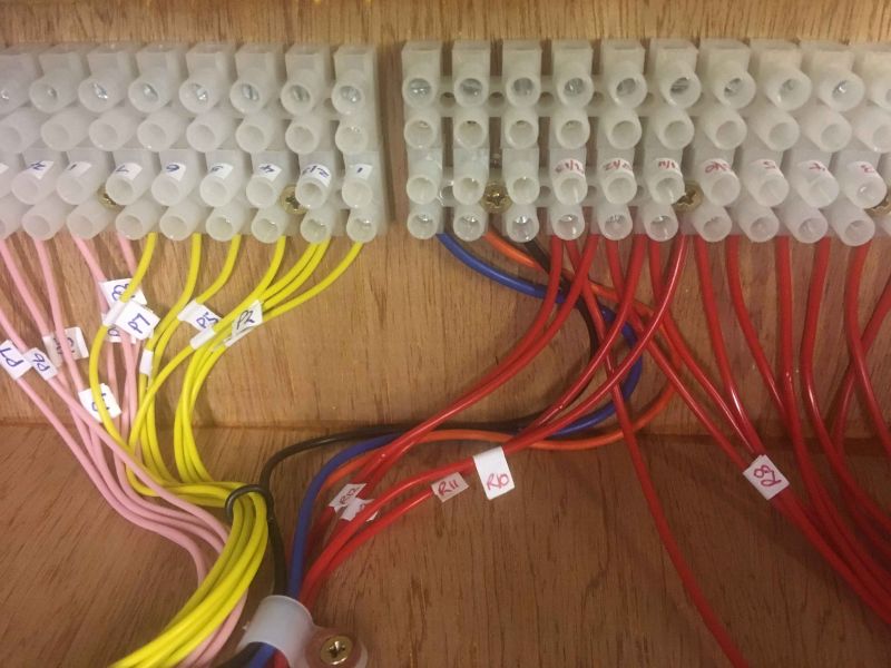
All main track wiring (24/02) for module 1 complete with individual red power feeds (serving each isolation block) bundled together ready to connect to a D-SUB 15 breakout which will be used to connect across to module 2.
All the module 1 red power feeds connected to the D-SUB 15 breakout and labelled. The same setup will be used on the connecting side of module 2, which will then feed into control panel 1
The same method of connectivity across the baseboards (module 1 to module 2 for example) is used for the point solenoids, eventually feeding into control panel 1.
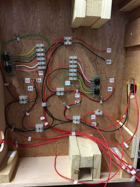
Here is the underside of baseboard module 2, showing all track power feeds and point motor solenoid feeds for both modules 1 and 2 converging on the plug choc blocks secured to the underside, complete with labelling.
Also the CDU for point switching is fixed here and all will feed into control panel 1 which will be fixed to the side of the module (to the underside of where the choc blocksare as you view them.
You will also notice 24/02 blue and orange wire to the bottom of the photo feeding into the connection block. These are feeds that run from all power isolation switches (on-off-on) on the control panels and to the power controllers - means I can operate CAB Control with either controller able to operate a loco for the whole length of the layout. See the my other threads (Braughing to Standon Branch I think) when Trevor helped me design this setup.
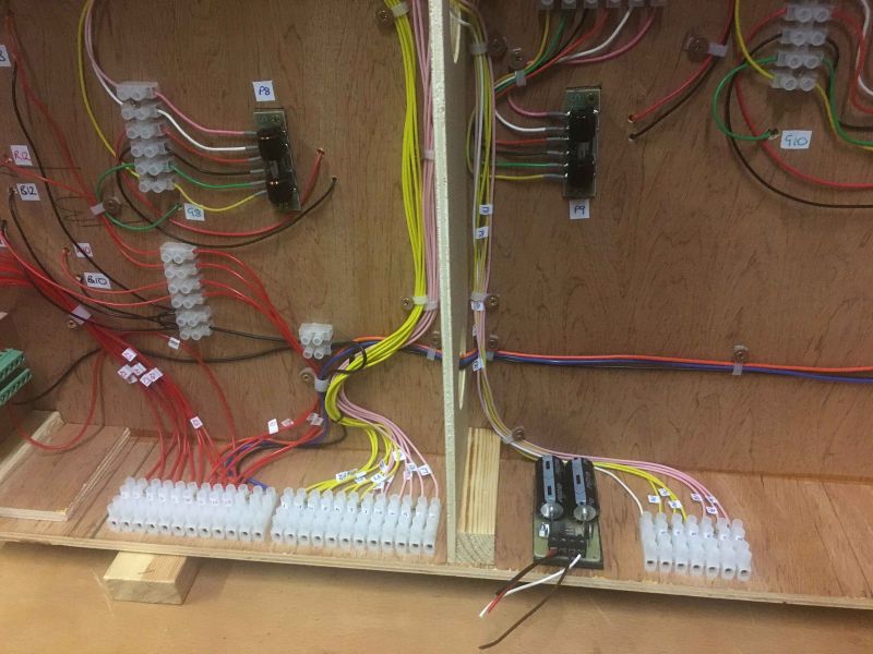
A close up of the same.
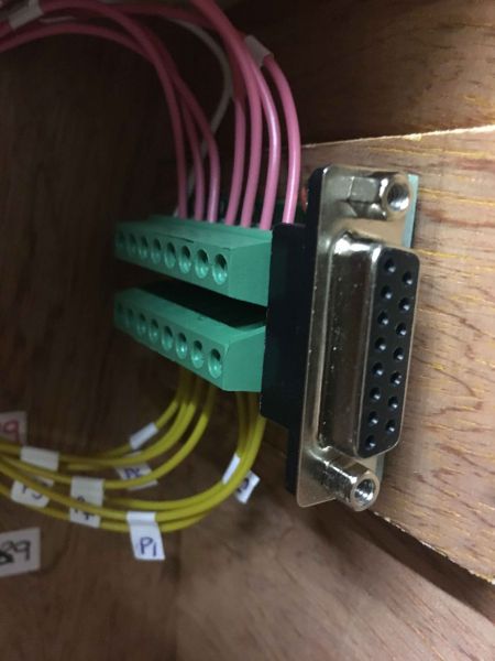
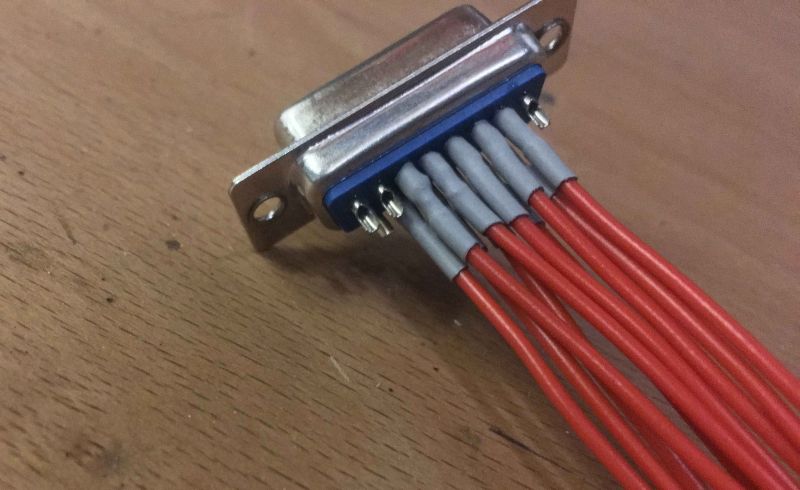
As mentioned earlier in the thread, the standard D-SUB 15 pin cables seemed not to be up to the job in powering the points to a connected module … so I made my own after purchasing a male / female pair £1.50 from RailwayScenics, using existing 16/02 wiring and then some plastic sleeves (75p each) also from RailwayScenics.
Was a little tricky as you can just about fir 16/02 wiring into these but taking your time and using a good soldering technique it can certainly be done and guarantees excellent power transfers across the modules. I used the same principle for both power and points connections across the modules.
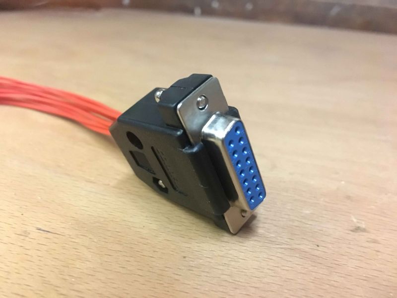
With cover sleeve attached - final part to do is wrap wiring with fabric wiring loom tape.
Home made D-SUB cable (fully populated) for the point wiring connection across the modules.

How the finished module 1 and module 2 wiring connections look like.

So thats about it. Please take a look at the main Braughing & Standon Branch thread in the next few days where I will post a few photos on the control panels .. and onward now to the scenics. :-)
regards to all
Paul
Posted

Site staff
Ron
NCE DCC ; 00 scale UK outline.
NCE DCC ; 00 scale UK outline.
Posted

Legacy Member
Im like Ron nowhere near as neat as yourself
Brian
OO gauge DCC ECOS Itrain 4 computer control system
Posted
Full Member
Paul
Posted
Full Member
I did start out neat with my wiring but it grew like topsy with additions here and there! So I would think Ron's and mine would be on some sort of par!
Well Done Mate and glad the wiring worked out … you got there in the end!
Cheers from Oz
Trevor
Posted
Full Member
Neat approach.
Module specifications usually have the connectors in the middle between the modules with block terminals on the boards. Two reasons - makes it easier to get at for connecting/separation (shows, trouble shooting), and only one connector set is needed between modules instead of two.
Nigel
©Nigel C. Phillips
1 guest and 0 members have just viewed this.