Track power connections across baseboard modules
Posted
Full Member
Paul, you wrote that the positions of the track changed but does that change the relative positions of the track blocks? The wiring can be easily altered for this! Having had a chance to think more about it do you want more switch isolating sections rather than rely on the points?
Again this is not hard but I personally think that you should be able to manage a lot of operations within the scope of the initial layout.
I know I used your SCARM diagram but mainly as a guide for myself with regard to module joins and the position of points. I was initially going to delete it once I finished but thought some other otherwise anonymous members and visitors might not quite understand what "blue lines" were meant to represent so I left it there.
Looking how broad the curvature is particularly in the "West station", while not rescinding my concurrence, I think that the curves should be more than able to handle the dynamics of a train backing over the S curve. The practice as Nigel put it is probably more appropriate for train set curves or at least relatively sharp mainline curves.
As for the East station, that crossover should not present too much of a hassle for most combinations of a loco and a wagon and an 08 and a single 4 wheeler which is about all it will be capable of holding. If those points were of the Set Track variety then I would wholly have to agree with Nigel as they are about as sharp as they can get but I would think still fairly reliable for the 08 and a wagon,
I've run this too much any way but do not be embarrassed to ask … you might help someone who is and cannot help themselves by asking!
Cheers and keep us posted!
Trevor

Posted
Full Member
Well spotted - I also see I posted an early photo of the baseboard frame without the top plywood sheet fixed … so you are actually looking at it from top down … as such there are no gaps and solidly glued… I've edited the previous post with the correct photo now.
Paul
Posted
Full Member
cheers
Paul
Posted
Full Member
Was more than happy for the SCARM diagram to be there and I knew why you did so … certainly does give a new viewer to the thread the real context of what we are discussing.
Yes .. the curves are planned to more than handle the dynamics backing over the S curve for my operational desires … as will the short crossover at the East station yard - the single 08 and/or with an attached 4 wheel wagon will be fine - what you dont see on the SCARM is there is a large Grain store a little before that cross over where some wagons will be pulled in, the 08 then using the crossover to pass back and return to some other wagon duties.
cheers
Paul
Posted

Full Member
S-bends (railway, not under the kitchen sink variety): They will work fine as long as the track radius is fine, which for N scale should be a minimum radius of 18", preferably 24". The issue is a simple practical one.The "no S over a module join" is a standard followed by all the modular groups that I'm familiar with. That said, most of them have the track towards the front, which is where Newton becomes an issue. There is also a potential issue with turnouts as part of an S where the points are incorrectly set.
Nice to see those cross-supports in place. You might want to sister-in a 3 or 6 mm section of ply on the inside of the ends - 12mm (0.5") thick is more normal, as well as on the underside of the end compartments for the terminal barrier strips, circuit breakers, kettle outlet, etc. If the top is 9mm that is not really enough depth for screws to bite into.
Nigel
©Nigel C. Phillips
Posted
Full Member
Rechargeable devices exist that use three-pin XLR connectors. These can be found on electric powered mobility wheelchairs and scooters. The connectors carry from 2 to 10 amps at 24 volts. I have found fine for DC power for the bus wires on the railway
Posted
Full Member
You might see that the first module wiring for my Braughing to Standon branch layout is close to completion (see link … if I copied it correctly) http://yourmodelrailway.net/view_topic.php?id=15714&forum_id=9#p281730
and the time now approaches for the connections across baseboard preparations. Earlier in this post is good advice on plug-able terminal connectors, RCA and XLR connectors all of which will work perfectly… but just wondered if anybody has experience of DB15 breakout board terminal connector as shown below … for me this looks like great combination of terminal block use (no soldering & easy to swap out if necessary) and simple 'plug n connect' with short D-sub cable across to the next baseboard. Approx £4 each.
Below model is rated as 21-24AWG, Voltage 300v, Current 10A - is that suitable for 7 x power (block section) supply wires of 24/02 using the standard 16v power supply unit …. to this electrical novice it would seem more than adequate but please advise if I'm mistaken.

thanks
Paul
Posted
Full Member
More than adequate for your purposes, and it should withstand extra current that would flow with any derailments or short circuits that would occur which is why the extra current capacity is a good thing. The power rating goes up infinitely when a short occurs even momentarily before the other fail safes such as fuses etc come into action.
Go ahead Mate
Regards from Australia
Trevor
Posted
Inactive Member
If you intent to use the joint in the boards as the end of blocks .
The method I use is to use TWO insulated track joiners at each end of both tracks.
Each joiner has half of one end cut off , leaving the insulated cross piece in place .
Using a standard track joiner to align the tracks ,I then separate the join , and fit
the two insulated half joiners and then screw the tracks in place
A small blob of super glue then holds the insulated joiners in place .
I have found that the two insulated cross pieces allow for a large expansion of the
track , while allowing the gap to be fully closed .
Each track on either side of joining sections , should have their separate power supply ,
through a detection sensor .
Regards Ted
Posted
Full Member
Hi Ted …. thanks also for the suggestions although in answer to your question, no I will not be using the join of the baseboards as the block ends … I'll be using loop wires to ensure connectivity continues until the next block end is reached - Trevor and I discussed this earlier in this thread if that helps.
cheers
Paul
Posted
Full Member
Can anyone advise where I can get a 15 pin male to male cable to connect to the DB15 breakout connectors I showed in the image a couple of threads back …. really having problems locating such cables from all the normal sources - even a male to female would suffice??
Thanks
Paul
Posted

Full Member
https://www.ebay.co.uk/sch/i.html?_from=R40&_trksid=m570.l1313&_nkw=15+pin+males+to+male&_sacat=0
Any good?
Bill
 Last edit: by Longchap
At 6'4'', Bill is a tall chap, then again, when horizontal he is rather long and people often used to trip over him! . . . and so a nickname was born :)
Posted
Full Member
Thanks
Paul
Posted
Full Member
I have now finished all the wiring x 4 modules and tested ok - good so far - and have received the first 4 x DB15 breakout board terminal connectors in ordered as shown in the above posting on Tue Sept 11th.
I am still finding it tricky to find the right lead for these and having been researching purpose made computer cables for these DB15 type of connectors (2 rows of pins), I'm a little worried a purpose made cable might typically be designed for computer game port connections, data feeds, etc and might not be up to the job of conducting CDU point switching connections or sectional power wires for a railway layout.
Perhaps I am being overly cautious but I'm not sure whether to locate some purpose made cables (approx £5-6 a throw) or just buy some male / female connector sockets and make up my own cables using 16/02 wire?
What is the advice please guys?
Thanks in advance
Paul
Posted
Full Member
You are bridging 3 gap sets with your modules… on my my now past clubs used computer connectors over 5 such gaps for a layout and it ran without an issue electrically anyway… it did have quite a few mechanical issues. I think the use of N scale and that you have local controls for either end will make for few problems if any!
I would be checking out ebay or similar for connector cables as that £5-6 seems a bit steep to me to wit
https://www.ebay.com.au/itm/2-Pcs-15-Pin-VGA-Male-to-Male-Connector-Cable-for-PC-LCD-Monitor/400995550155?epid=1139213130&hash=item5d5d3283cb:g:6xYAAOSwzlZaSm23:rk:36:pf:0
Hope this helps
Trevor
Last edit: by xdford
Posted
Full Member
The leads I need are actually DB15 (also known as DA15 Game Port) computer cables with 2 rows only (8&7 pin) and not the VGA 15 pin which are 3 rows of 5. So the connecting terminals and cables need to be as shown below-
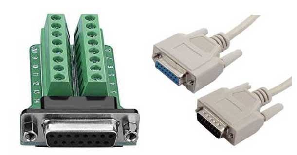
These cables I can find on ebay for around £6.81 but not much cheaper - link to item below.
https://www.ebay.co.uk/itm/Computer-DB15-15-Pin-Male-to-Female-Connector-Extension-Cable-White-4-9Ft-Long/183144513818?epid=2089168951&hash=item2aa443811a:g:vjkAAOSwQUhatgyE:rk:1:pf:0
I think this sterling price is pretty equivalent to AUS $12 so wonder if you thought I said £56 in my earlier post Trevor?
Thanks again
Paul
Posted
Full Member
Amazon here has M/M DB35 cables.$8-$11 US depending on the length. You can always get the ends and do your own (10 M for around $13). Or use a M/M gender changer (this would give a -F/M/M/F-). A lot of HD15 (5/5/5 three row) cables are mislabeled as DB15. Amazon UK should have the same. Just checked. They do, and about the same prices.
Late in joining this, MOLEX connectors offer much more choice, less chance of bent pins, and come in different amp capacity. More work though.
Nigel
©Nigel C. Phillips
Posted
Full Member
You could try making yourself a small wooden block with 2 slots 9mm apart with a square end and use that as a holder for your rails while you use the razor saw similarly to a mitre box. If you are really canny, you could get it to sit over the track and sleepers and hold the lot so that it does not move.
The problem you will have is that the force you would be using is many times that which would be applied in a scale sense to the rail. You also would not have quite the grip on your rail soldered to the PC board as it is only a small surface.
If it of interest to you, I have been laying track on many and various layouts (my own, club and those of others) for nearly 50 years in N, HO, OO, On30 and O scales, and I have for most of that time, only used a razor saw.
Mae sure that you get as fine a set of teeth as you can on the saw. I use Atlas Snap Saws myself and find that they are a good size and tooth combination…
Hope this helps
Regards
Trevor
Last edit: by xdford
Posted
Full Member
Posted

Full Member
Staying on the thread Kevin.
1 guest and 0 members have just viewed this.