Track power connections across baseboard modules
Posted
#234166
(In Topic #12841)
Full Member
This means I will have 3 baseboard joins to negotiate and as I'm now laying / positioning out track now and pinning it temporarily to ensure all fits well, the track is cut but aligned really straight and tight (2mm gap) at each baseboard join - the joins are all straight runs, no curves nor points involved.
Now these joins could form rather handy isolation points for the blocks of power I have planned (thanks to Trevor his constant advice on that topic) but what is the best way to ensure the loco moves across the joins in terms of constant power? I've seen various images on Google searches that use brass screws, brass plates, small track bridging sections and many more …. but could be that is more for a DCC operation although I'm not sure.
In terms of DC, would it work perfectly well across these joins if power was provided to both track sections on each module and with such a small gap (2mm), the loco wheels would span this easily and keep continual power flow?
I doubt it would be that simple and probably I'd need temporary joiners in place when clamping the modules together ….. or something more durable??
Thanks again for any advice.
Paul

Posted

Site staff
You could use multi pin connectors.
Ron
NCE DCC ; 00 scale UK outline.
NCE DCC ; 00 scale UK outline.
Posted

Full Member
If you have fewer wires the same can be achieved with DIN plugs.
I would advise that you don't rely on gaps in the rails between boards to provide isolation, or anywhere else for that matter without providing some sort of barrier between the rail ends so that they cannot touch, it is bad practice. If temperatures in the room increase the rails can expand and touch, not what you want if it is an isolation point. If you are using Peco track then the plastic isolation joiners can be used or alternatively a small piece of plasticard slipped between the joints and fixed with superglue can be used. When set trim to suit the rail profile with a scalpel or craft knife.
Posted
Full Member
You could do it with 3 wires running the length of the layout and using short leads and banana plugs and receptacles that you can easily lift out and replace and keep the wiring in line for the extra wires just use extra plugs… D plugs will also work well as mentioned earlier.
Let us know!
Cheers
Trevor
 Last edit: by xdford
Posted

Full Member
If you are going to use each module as a block they should be wired independently. Gap of 2mm seems a bit wide as well. Mine are 0.5mm, more than enough for any expansion if you have similar gaps in the flex track. If you have blocks start and end away from the joins using insulators, better to have known power between modules. Easier to troubleshoot.
I use Anderson Powerpoles for the power bus (buss over here), rated for I think 30 amp. Silver coated connections, corrosion resistant. Simple snap fit. Dropper every 3 feet for the track.
Doesn't matter whether it is DC or DCC, reliable connections are a must, whatever the connector. Wire it as if you were going for DCC. If you don't and you do you will regret it later on.
Nigel
©Nigel C. Phillips
Posted

Inactive Member
BR Blue Post Tops
Posted
Full Member
Will not be using the module gaps as isolation points nor block sections …. keeping things as simple as possible yet organised and structured based on the diagrams I've been working on with Trevor.
Too damn cold in the garage of late … -3 already tonight … so only quick pottering time on the layout at the moment so plenty of time to research … and ask you guys for valuable feedback!! :-)
cheers
Paul
Posted
Full Member
Out of interest, how often do you think your modules would be stored/taken apart / reassembled? If it is only occasionally I have an idea what would be (I think) fairly straight forward and avoiding difficult to locate crossed wires under the layout but again it is what you are comfortable with!
Cheers
Trevor
Posted
Inactive Member
like this..

Now I've finally started a model railway…I've inherited another…
Posted
Full Member
@Trevor - I don't anticipate the modules being taken apart and stored too often TBH but it does depend on circumstances. Currently I have near double length garage so plenty of room … plus I can even change the storage racks position to make more room if necessary. I can think of just splitting into 2 x 2 modules to half the length in size is a more likely scenario and the only time I can envisage breaking down all 4 modules would be the occasional local exhibition (maybe 3-4 per year). The tricky time will be if I move house and not have such a lengthy garage which may on the cards in a few years time so not an immediate consideration …. so prey tell Trevor.
cheers
Paul
Posted
Full Member
Actually using small banana plugs but Queran's idea would work just as well with what I have in mind. I will do a diagram based on Queran's idea plus one of my own but we are busy today so will not get to it till tonight . I will make the assumption that your control panel for each station will be on the two end modules which will be where your operators (or just yourself for that matter) will work from!
Stand by…
Regards
Trevor
Posted
Full Member
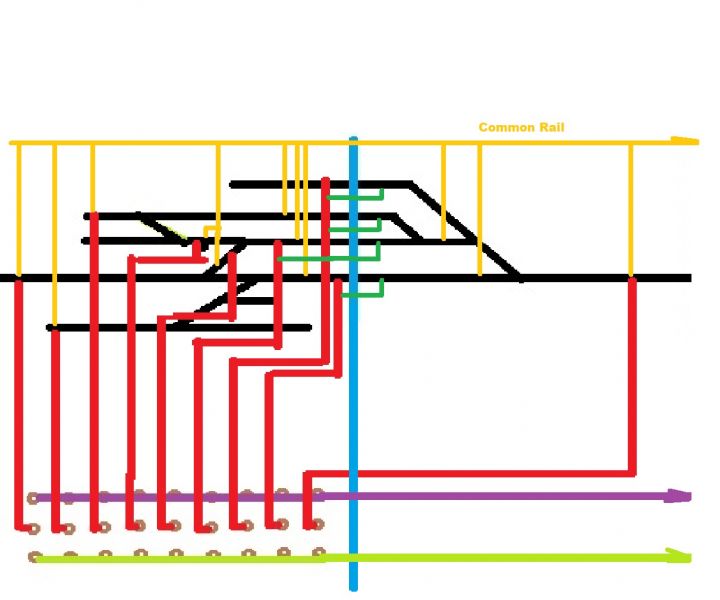
Here it is but it is minus the common rail connection and the jumpers at this point but it should be easy to work out where they should be!

The switches are abbreviated but are in the order I initially presented with the exception of the 4th and 5th switches on the West Station which I have transposed for clarity. Schematically the wires are quite a way apart but can be adjoining but this I think you are following OK.
The Light Blue line represents the break in the boards
Purple represents the A train controller
Light Green represents the B train controller
More to come and apologies about the slower than I anticipated rate of progress,
Regards
Trevor
Posted
Full Member
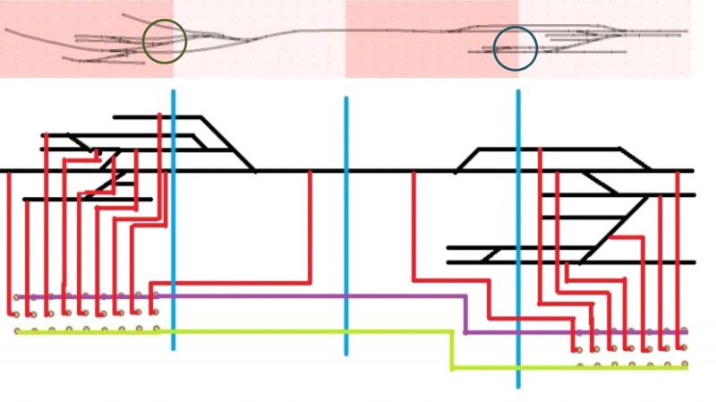
Here it is

The Dark Green wires indicate where (I think) there should be a loop wire to ensure continuity between the end board and passing sidings etc in the middle.
Again if anyone can pick holes in the connections let me know,
Regards
Trevor
Last edit: by xdford
Posted
Full Member
This is how I envisaged your connections to be. RCA plugs are tight and the advantage would be that if a cable broke down (a rare event I know but it does happen), you would not be taking out all your other connections in a D plug!
Here it is as a plan anyway…

Queran's blocks will work like this as well and just as well
Cheers
Trevor
Posted
Full Member
The Western Station with the jumpers etc
Hope this has all been clear enough to follow, and that it helps a few more members
Regards
Trevor
Last edit: by xdford
Posted
Full Member
Comprehensive wiring plan there from Trevor (although to my DCC eyes there are a couple of places that will be dead depending on which way the points are thrown. Part of the operating plan?) I just noticed on the track plan that you appear to have 2 points with the throats in close proximity to the ends of the modules - far left and far right modules. The 2 modules on the left also have a reverse curve over the join. Best practice is to leave at least 6" of straight track either side of the join to allow access for track wiring, jumpers, point motors, live frogs etc., and no reverse curves. Anything less than that is difficult to work with or in, especially from underneath, and depending on your track radii long stock may foul stock on nearby track when going through the S.
Nigel
©Nigel C. Phillips
Posted
Full Member
There are a couple of places where the Electro Frogs will shut off power to different sections like Insul frog points but there should be no short circuit the way I have put in the insulated joiners … it was a balancing act to anticipate his operations and needs for different movements and I hope I have got that balance fairly right!
I concur about the S bend factor but in following the prototype, there probably is not much option and N scale seems to behave differently with train dynamics compared to the larger scales in some aspects. Paul will have to test that for himself as I have been with my own layout with relaying and adjusting ( and I only have relocated mine, not started again from scratch!)
Cheers
Trevor
Posted
Full Member
I'll digest much more over the weekend in case I have questions but looking at what you have done so clearly I'd be embarrassed now to ask.
What a gent, thanks once again.
Paul
Posted
Full Member
Trevor is correct and my operating plan of rolling stock is liking less busy than you think and as such risks of fouling will be likely well mitigated; couple of possible dead point throws are accpeted. I understand what you mean about 2 points throats being less than 6 inches from the module joins but i have a fist width (nearly) underneath the baseboard at all points positions so I'm pretty confident I have enough room for wiring, point motors, etc (see baseboard design below) and I took quite some time to move around the track design in N gauge paper track stencils to ensure the points all had good clearance from the baseboard cross members.
Also, I noticed that Trevor depicted my original pink / white overall layout image as a reference point for his diagrams - perfectly fine, however it was only a SCARM based image and once I began to transpose the layout for real on to the baseboard and laid the cork track underlay with real track as guiding markers, it become clear that some shifts in track positions and modellers licence came into play in order all the points and track were aligned correctly - the point being in real life the track on the layout is now somewhat different in terms of spacing, etc and your concerns may well be mitigated already. I'll try to show that in a later photo once all the track is pinned in place.

cheers
Paul
Last edit: by Padster
Posted
Full Member
Nice looking modules - 2 x 4 feet (I was looking for 4 x 4 feet modules and extra long arms, I think you meant 4 modules, 2 x 4 feet). So you're in N scale, big layout. See the green circles below for where I am talking about.
1. Space available at the ends of boards for point throats. My knuckles are 4" across, 6" is barely enough space to work in. Point motors are the same size for N and OO(HO), give yourself enough room to work in. Points affected are indicated within the two green circles.
2. I know the diagram is a work in progress, but you seem to have one hole in the end plates - is this for wiring to go though? If that's the case I'd advise against it as all that wiring (8 wires plus however many you will be using to power the point motors) will be opposite where the throat is in the LH module, and pretty close to the RH one.
3. Most module designs call for a terminal barrier ("choc block") at the ends of each module (not those light duty white ones rated at 5-6 amp, get some 20-30 amp ones with meat on them), screwed into the underside of the base. (Use additional ones where required for the wiring, makes life easier when trying to work out what goes where). This anchors the wiring, the wires go from there to the connectors, which are best left hanging where you can easily get at them. If you are using D-type connectors use some of that flexible cable protecting tube that slides on over all those wires or use multiwire cable with each wire rated at 10 amp minimum (a short can generate that or more and those controllers may not be up for it, I presume Trevor has recommended some sort of short protection for the blocks as part of the wiring). I would recommend one D-type connector for the power, one for the control, one for the point motors, lights, bells, whistles….BTY, I don't think it's really necessary to twist those power cables unless you are going the DCC route and want to prevent signal distortion
4. The S-bends are within the LH circle. One permanent, one depending on which way the switch is thrown.
5. I noticed that the lateral supports do not appear to contact the underside of the top, nor do the corner gluing blocks. You will need some sort of permanent, glued, support between the laterals and the top, as the ply will curve down with time (and weight of scenery and track). Even Baltic ply needs support. It will also act as a very efficient bass drum. You mentioned that it may go on the road - where will the legs go? I can't tell from the photo - is that hardwood veneer coated chipboard or plywood. Looks like chipboard.
Nigel
©Nigel C. Phillips
1 guest and 0 members have just viewed this.