Gladiator LNER/BR J6
Posted

Full Member
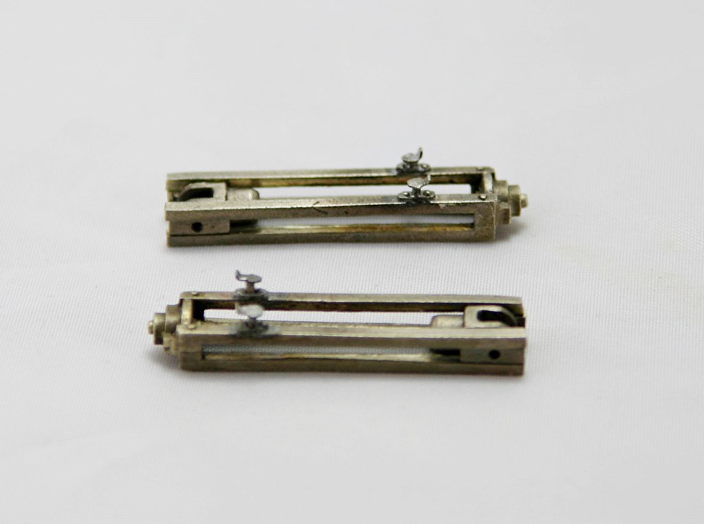
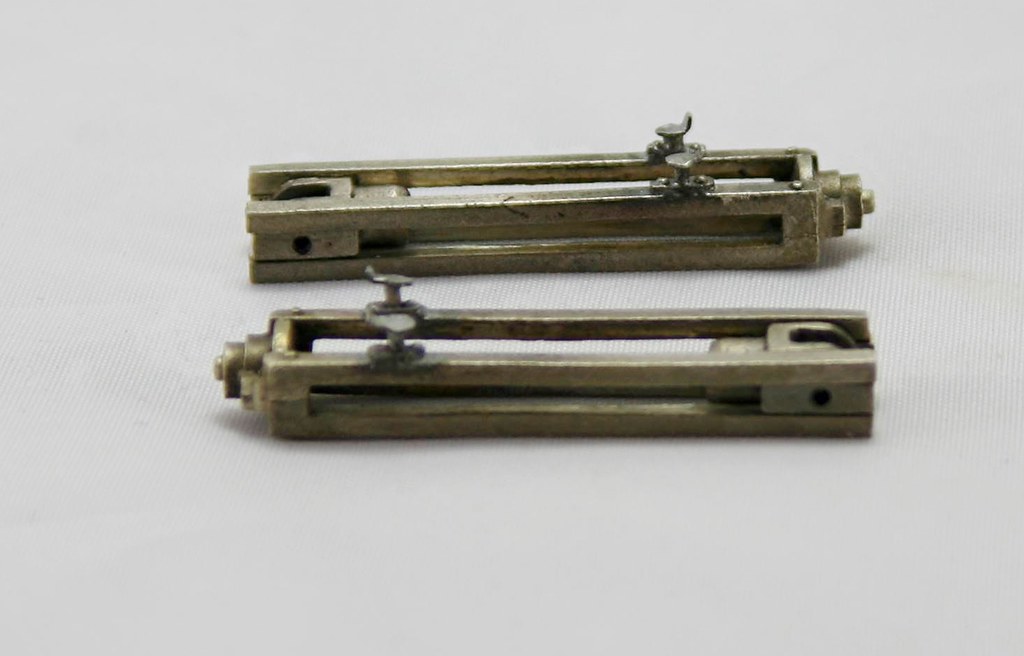
Once I had them running nice and smooth and having test fitted them in the motion plate, I detailed them with the very prominent oil pots on the tops. Made from spare etch and nickel rod
I am not sure why but these proved and absolute pain to take photos of…
Regards Rob

Posted

Full Member
John
John
Posted

Full Member
Another ardent admirer here, that is lovely work you are doing. 'Proper' modelling of very high order!
Cheers,
John.
Cheers,
John E.
My layout: http://yourmodelrailway.net/view_topic.php?id=15083&forum_id=21&page=1
Is this fair? Brexit and the future of tax havens - Tax Justice Network
John E.
My layout: http://yourmodelrailway.net/view_topic.php?id=15083&forum_id=21&page=1
Is this fair? Brexit and the future of tax havens - Tax Justice Network
Posted
Full Member
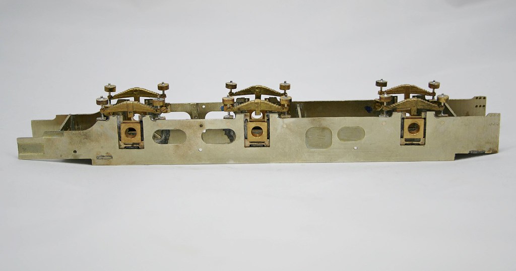
We now have all the springs attached to the frame. Initially I though to have the centre springs removable and the for and aft ones just soldered on but in the end I drilled and tapped them all 12ba so they are all removable should the need arise.
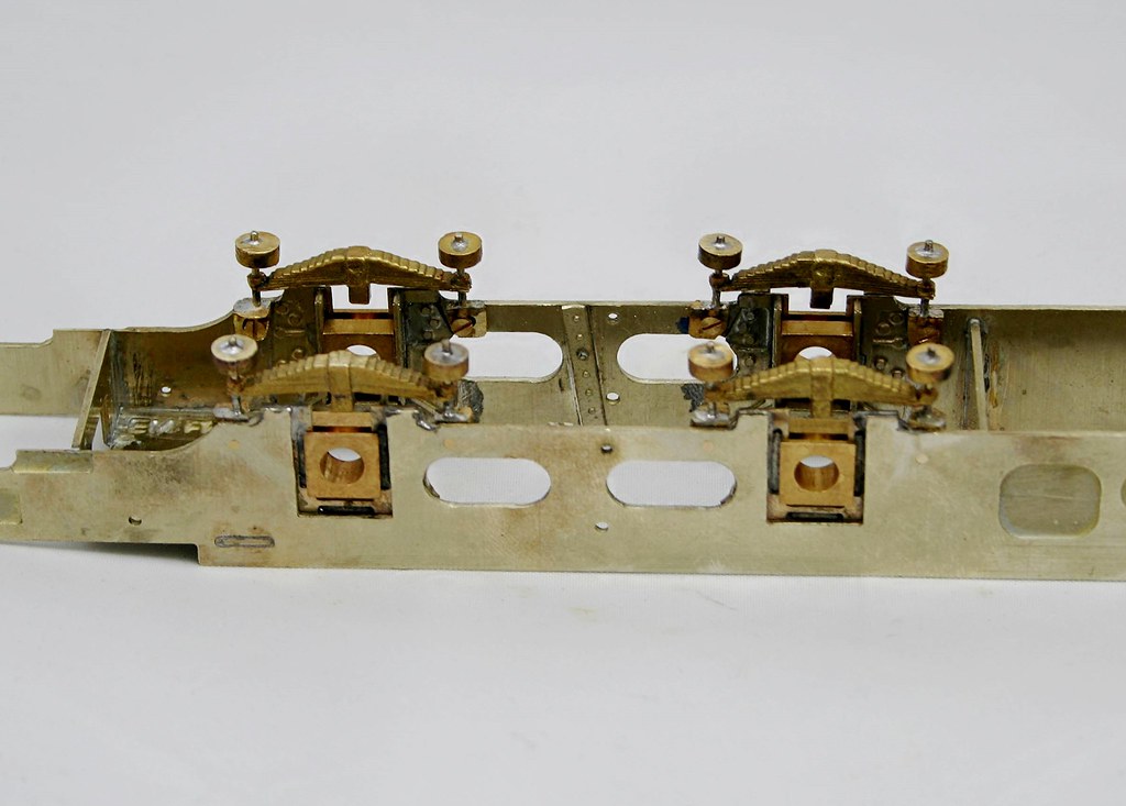
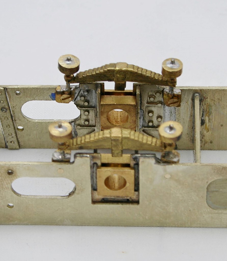
Regards Rob
Posted
Full Member
Regards Rob
Posted

Full Member
Posted
Full Member
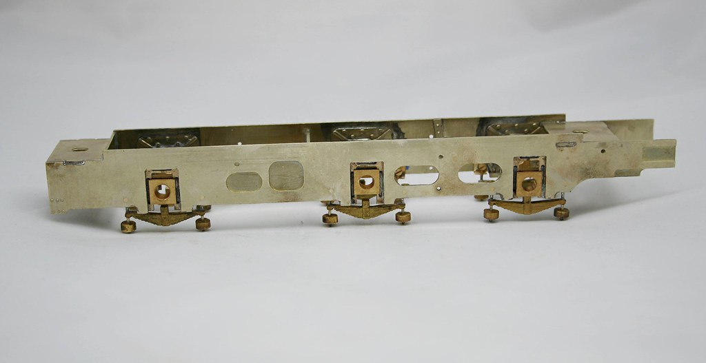
Over the last couple of evenings I have prepared the Finney Hornguides/blocks (nicked) borrowed from my A1 kit until I collect some more from the guys at Telford.
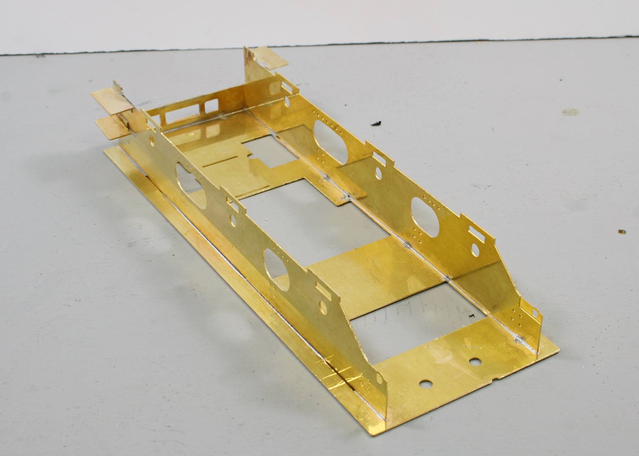
Then I started on the instructions which have you prepare the outer chassis first and then attach it to the tender footplate.
Here's where I got to on that last night.
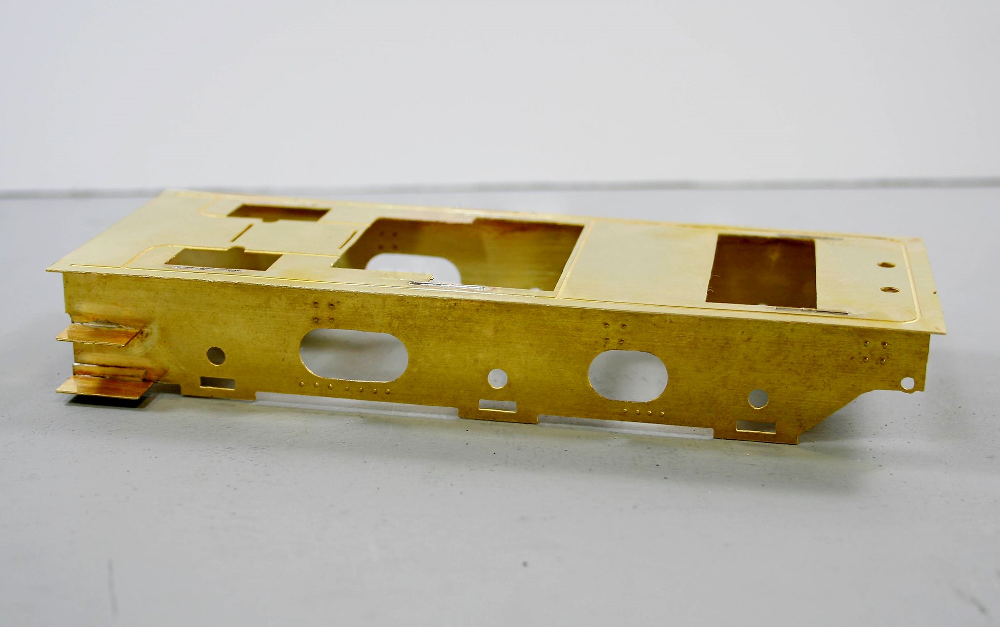
Regards Rob
Posted
Full Member
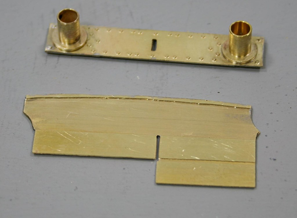
However, I will start off with a bit of a gotcha! The instructions tell you if modelling post 1940 to drill out two etched dimples on the rear right hand side of the tender for hand rails that must have been fitted to some tenders at some point.
Having done it I immediately started to think I wonder. Sure, enough when I looked at photos of 64206 which is the loco being modelled I noted no rear handrail….
So, I opened out the holes to 1.55mm and soldered some stubs of rod in - this is it from the inside
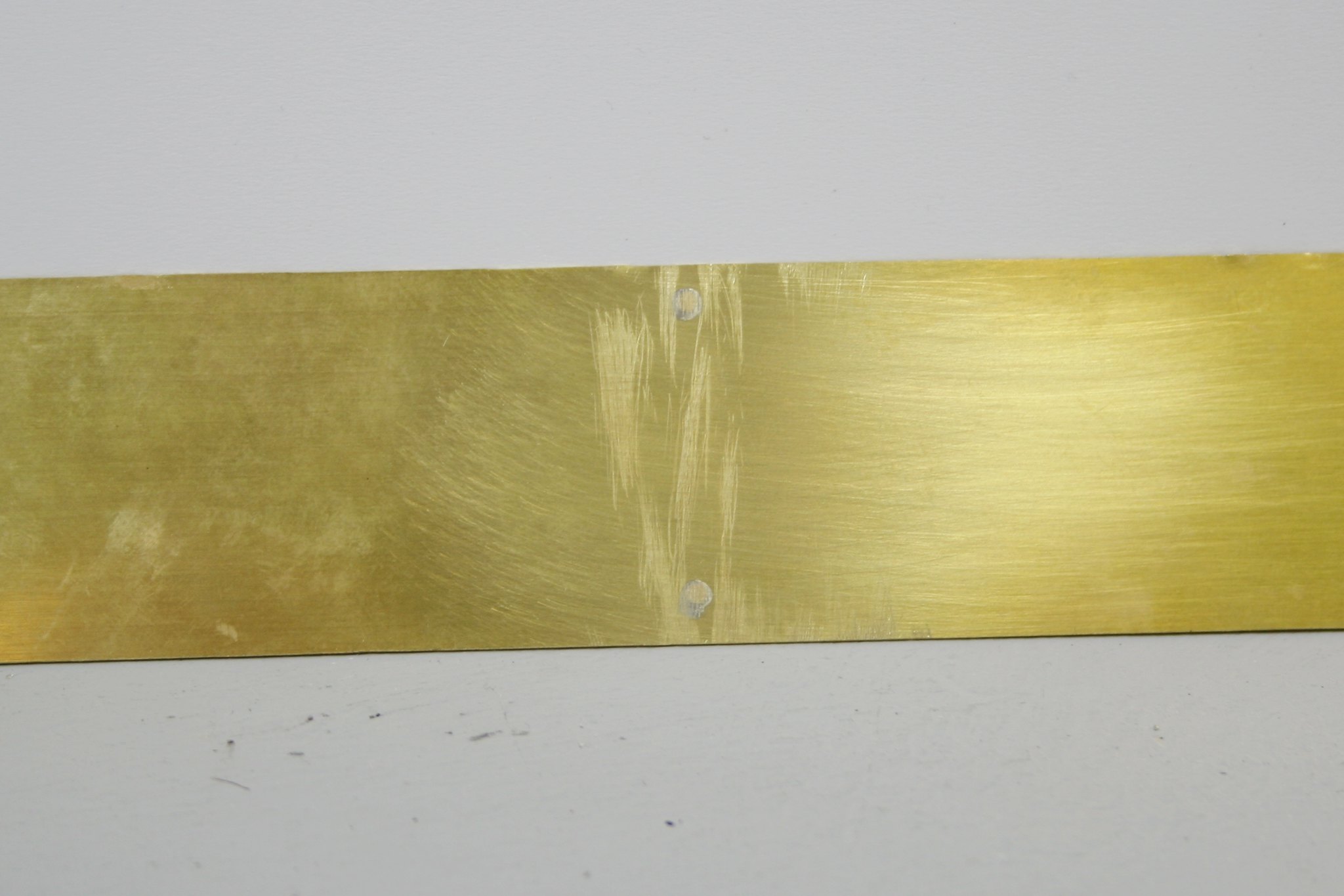
And from the outside - thankfully nothing shows
Next the tender sides are rectangular but on the real thing on the tender that I am working on there are cut outs for a handrail as in this example by Ron Bowyer.
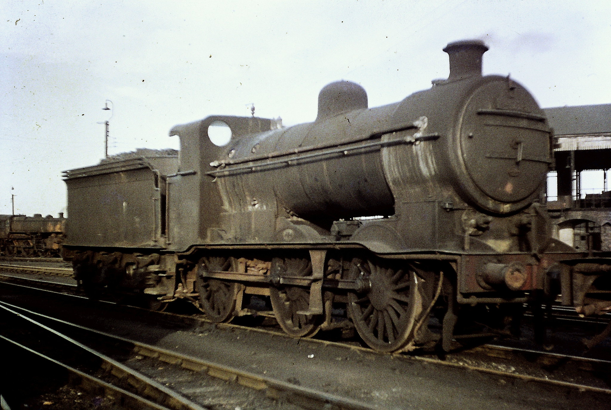 GNR/LNER Gresley "J6" class 0-6-0 No. 64223. by Ron Bowyer, on Flickr
I have to confess to struggling with the instructions on this point so I went my own way. There are sections of etched beading to represent this and having worked out for myself how I believe they are meant to fit I tacked them to each end
This allowed me to scribe a line to cut/file to and then I unsoldered them and removed the bits that needed removing. Time will tell as to whether what I have done is correct but studying various photos it looks right.
The next job was to drill out one of two dimples for the front handrail knob - these are design for a short rail where the top is cut out as I have done or a long rail where the side is left at full height. I drilled out the lower ones.
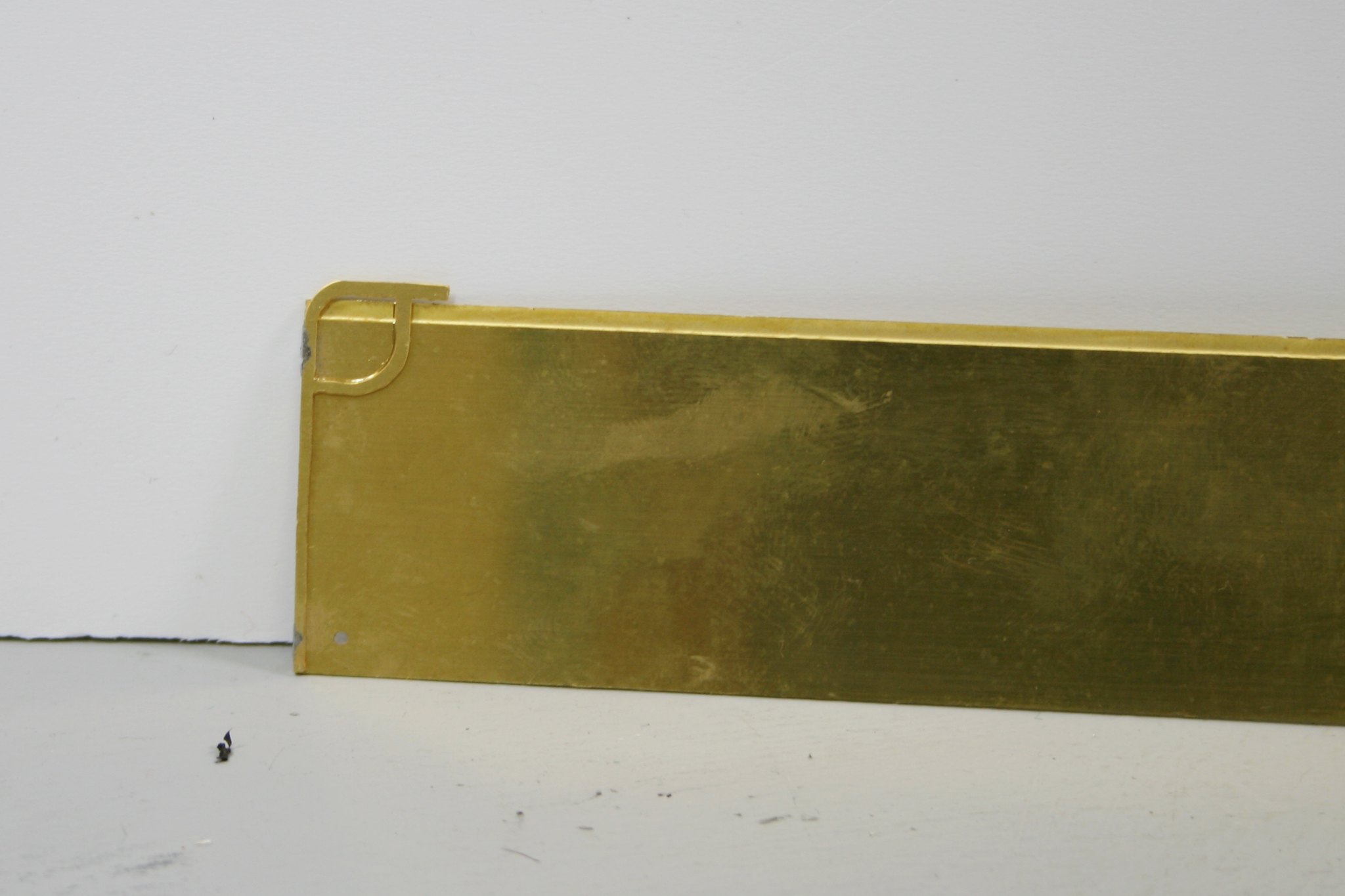
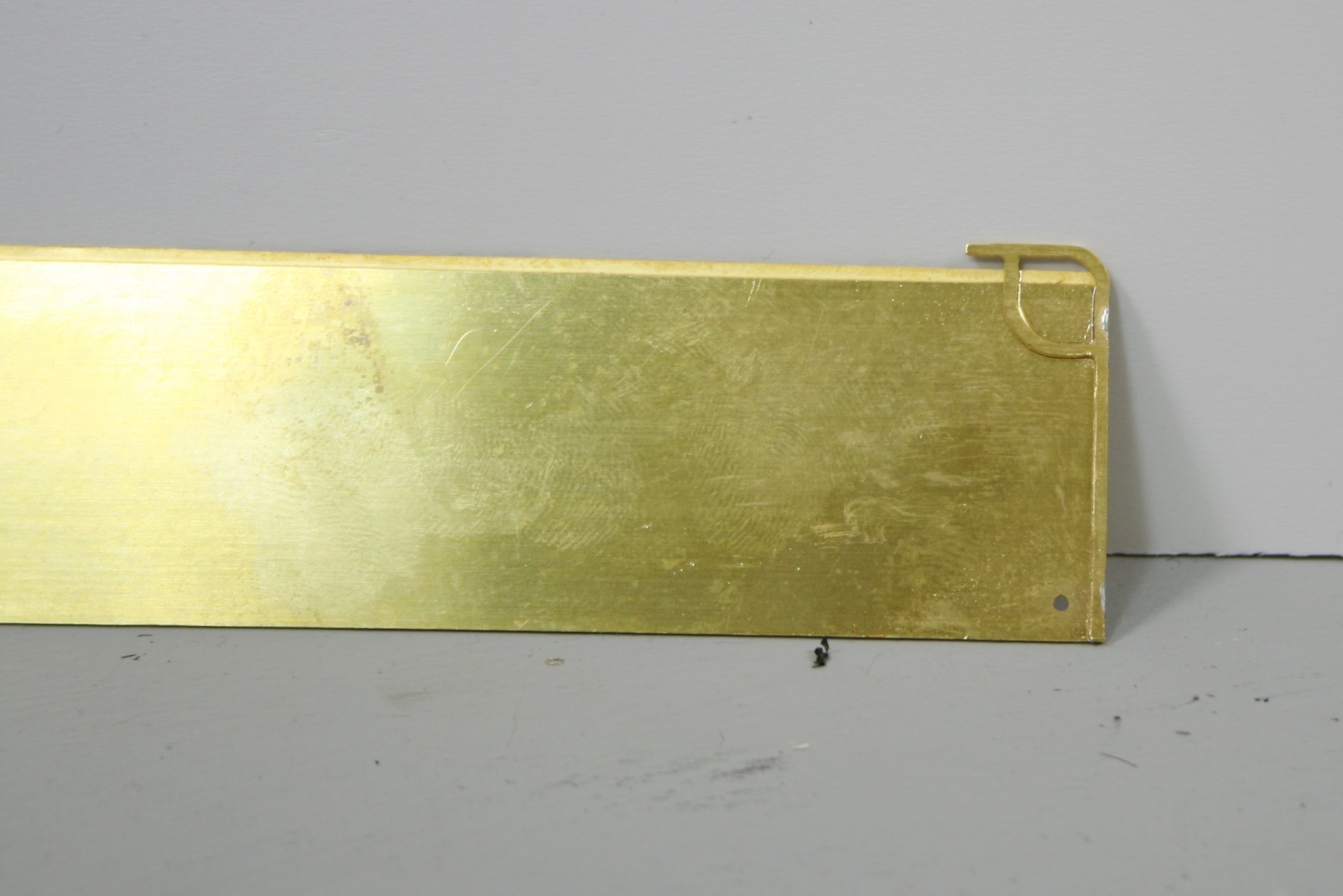
Then I carefully marked out where the first bend should be and then bent it using my Metalsmith Drilling table with a rod slightly smaller than the required bend clamped to it.
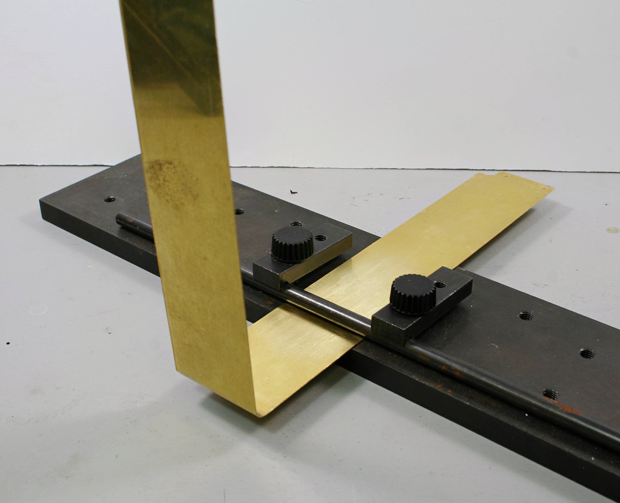
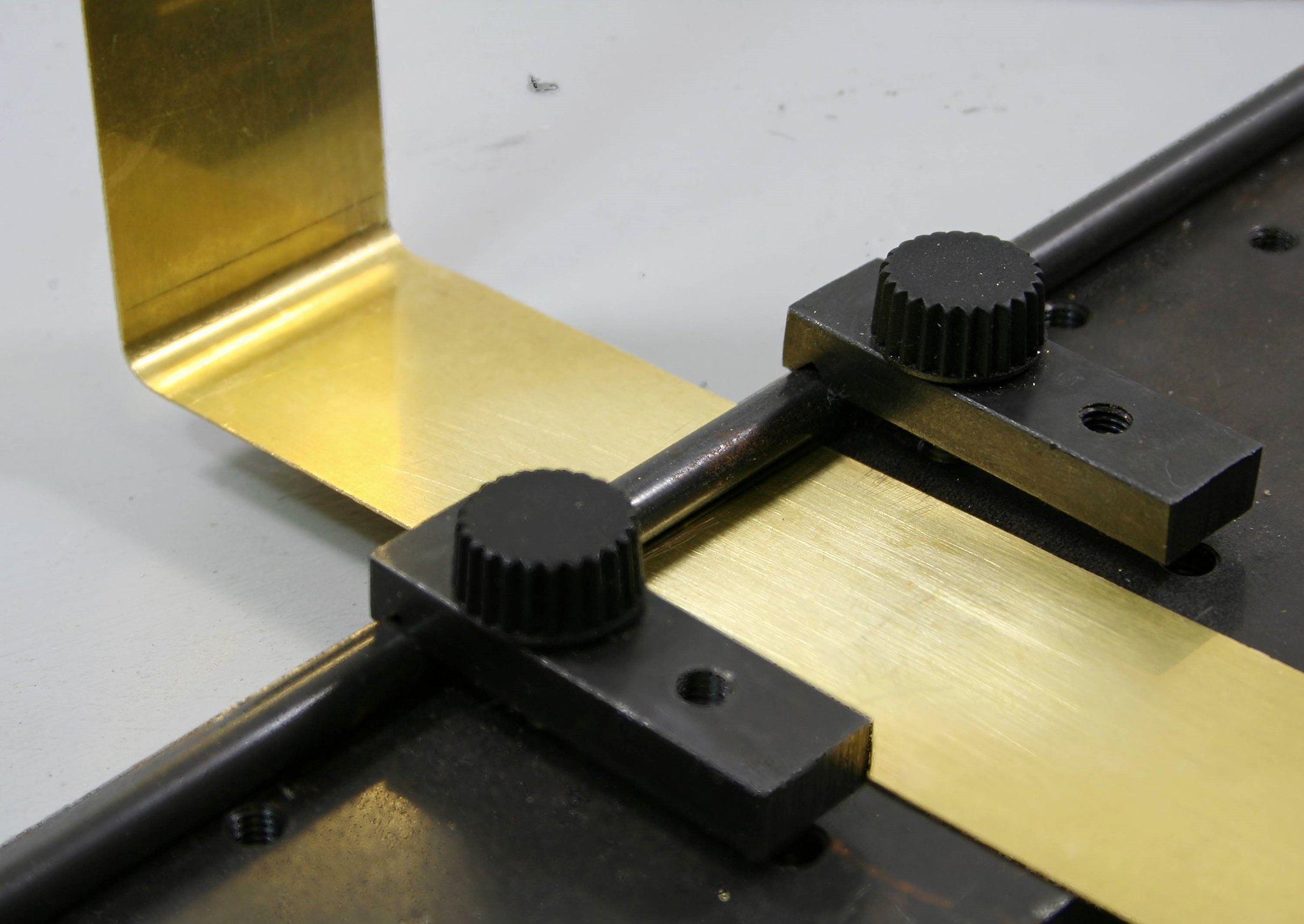
If this sort of thing scares you take heart. I didn't get it right first time, I just calmly straightened it with fingers and thumbs finally using smooth bladed pliers to finish off and them remeasured and tried again. The first side (the one in the photos) I got right on the second attempt. The other side took three goes…. but I got there.
Next up is to solder in the bulkhead.
Where the instructions are really lacking is that they refer to parts but don't number them so you are constantly searching the scans of the etches and the index to find out which part you are looking for - the scans are labelled with part numbers and there is an index but it would be so much better if the instructions had part numbers alongside the text.
Then lastly solder the side/end piece to the footplate.
Regards Rob
Posted
Full Member
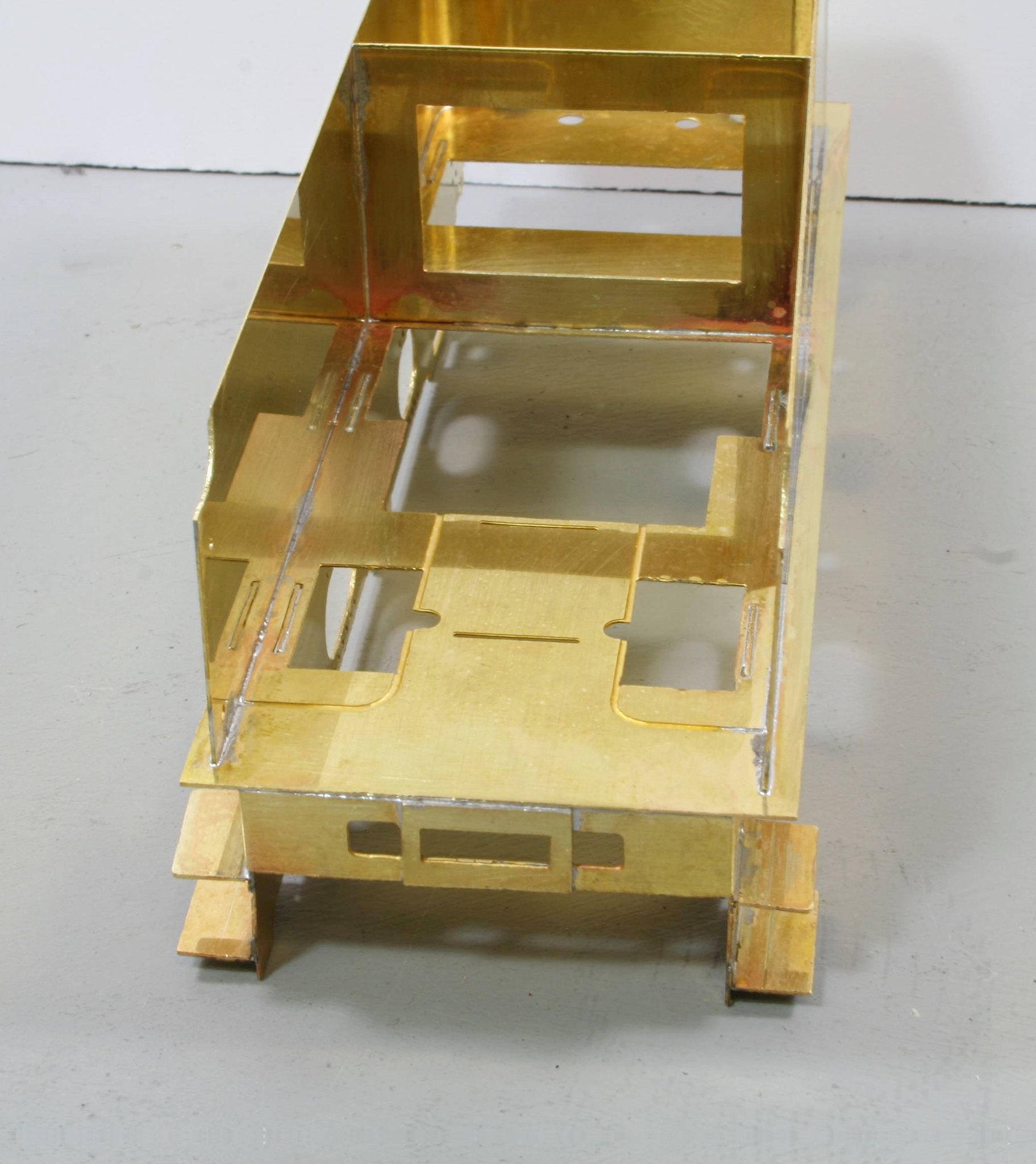
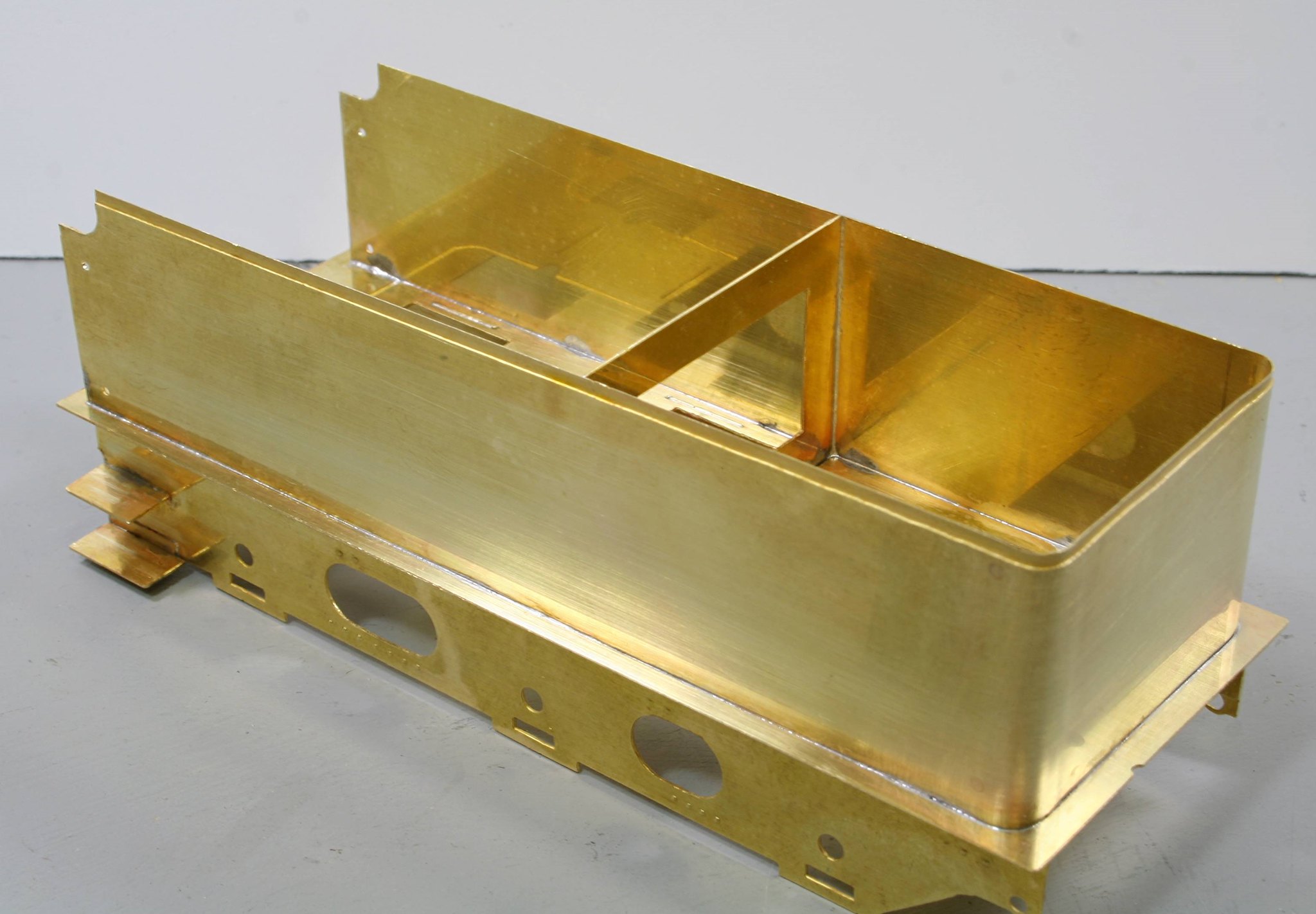
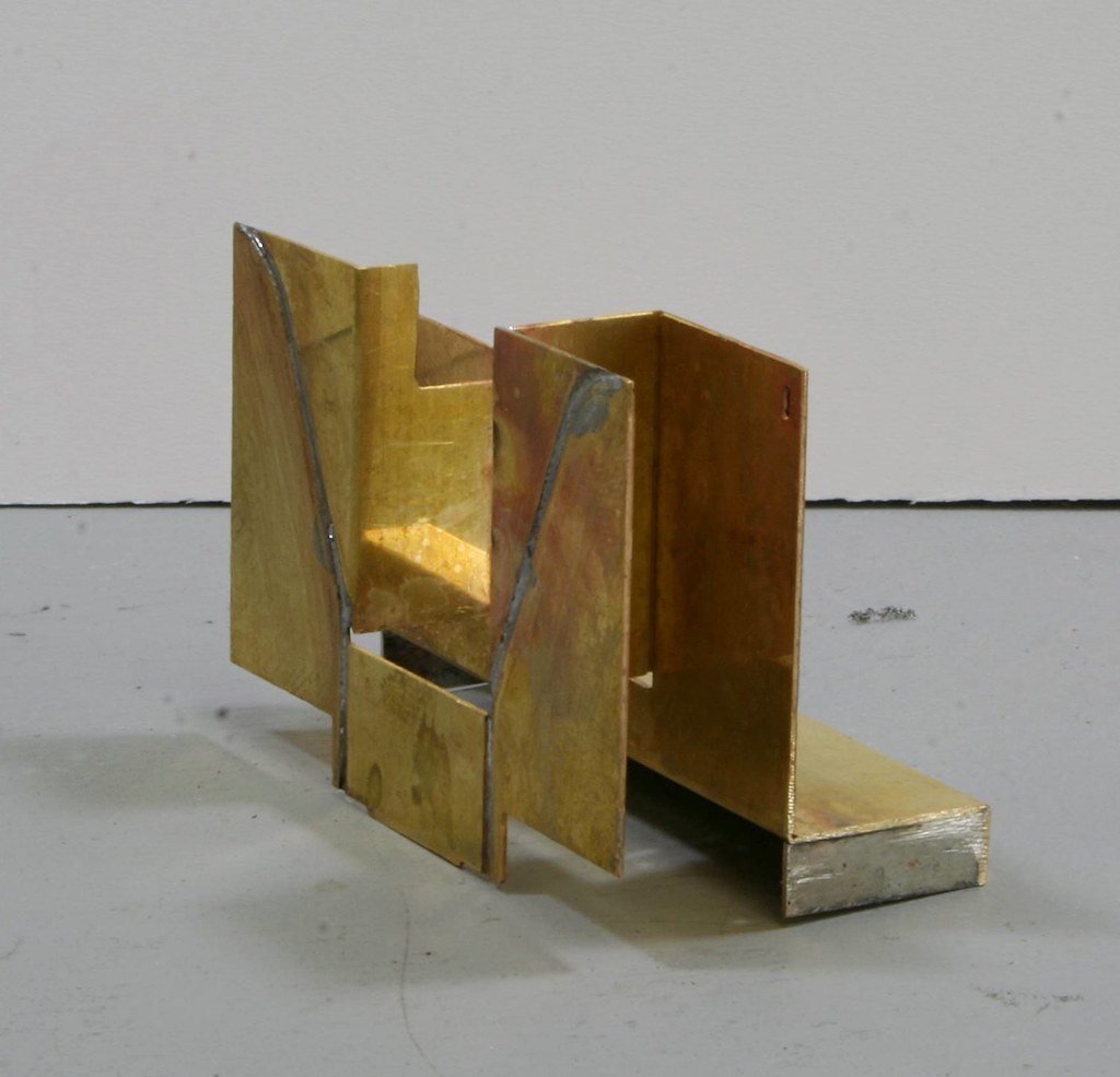
"Take coal space sides, note the handling and drill 1.85mm at half etched pops if fitting scoop and tank vents, then fold so that the sides fit into the coal space front plate, tack into position taking care to be square to front plate. Sit the assembly into it's slot in the sole plate and tack onto position square 'each way'"
I found the parts easily enough and put them together how I interpreted the instructions but then found that there was nowhere/way that they would fit.
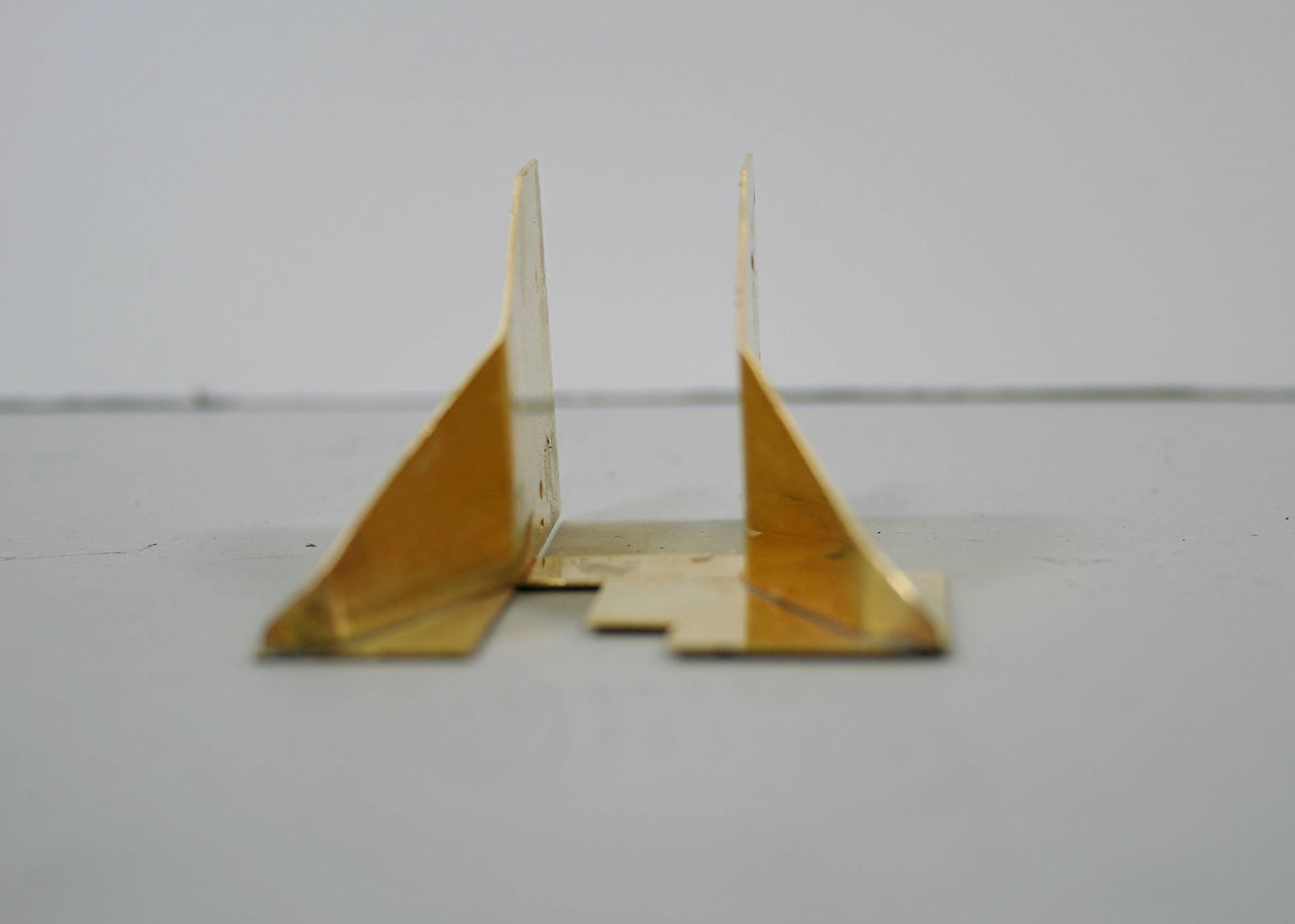
There is a plan and top down outline drawing supplied but I can't figure out from which bit is the coal space front plate or which orientation it fits in.
My only saving grace is that there is one of these tenders attached to the C1 Atlantic at Locomotion so I plan to see if I can get aboard it when I am there next weekend to see how the coal chute/plate is made up on the real thing.
I am on my way to Telford tomorrow so I will have better things to think about until mid next week.
Regards Rob
Posted
Full Member
By extreme good fortune this year I have taken photos of both. I had forgotten the other until today though.
The first one is located at Shildon, attached to the C1 large-boilered Atlantic and, as proposed in a recent post, I asked one of the museum assistants if I could be accompanied aboard to take photos of the tender top on Saturday and he obliged.
The other is attached by coincidence to the small-boilered Atlantic Henry Oakley whom I encountered at York earlier in the year. Although not great and I didn't get aboard, I did get enough details from my photos to work out which version I need for the J6 and more importantly that the coal space on the kit isn't quite like the two preserved examples each of which are similar but different.
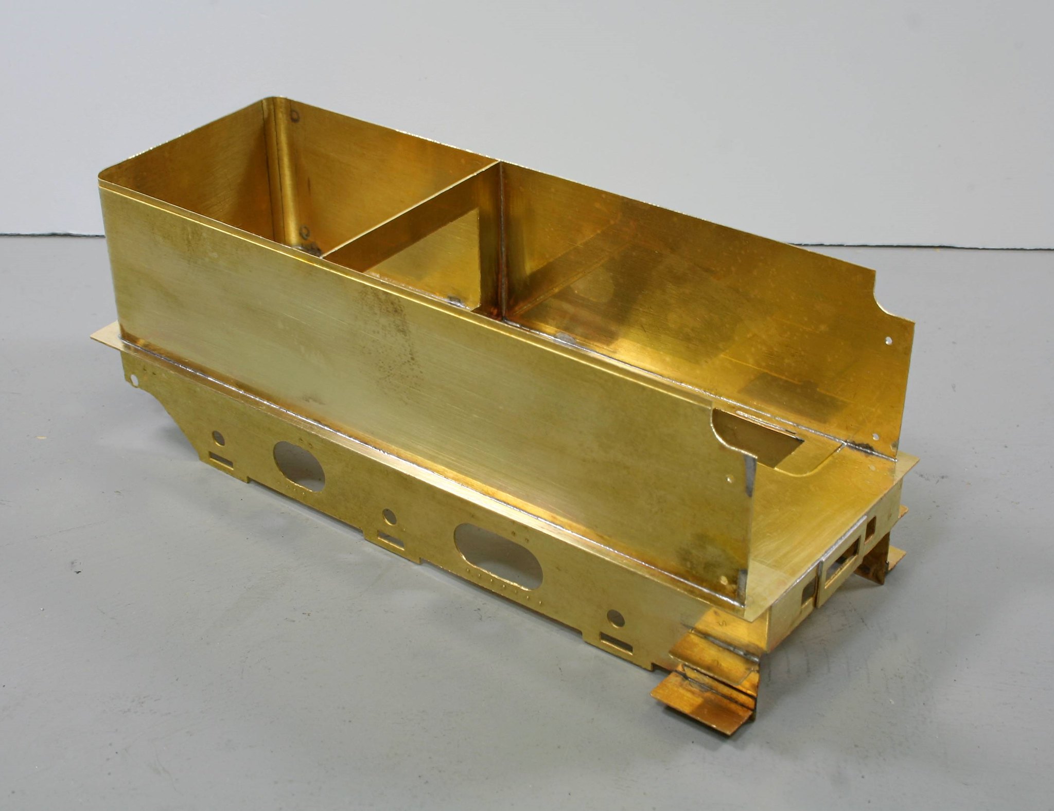
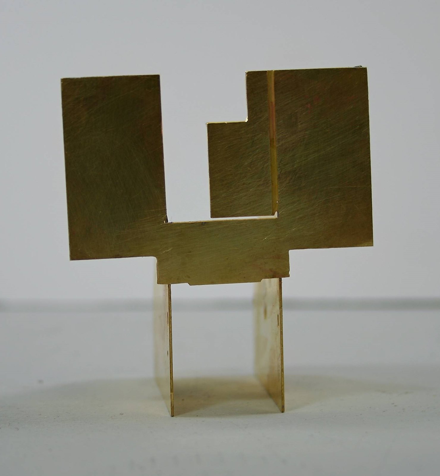
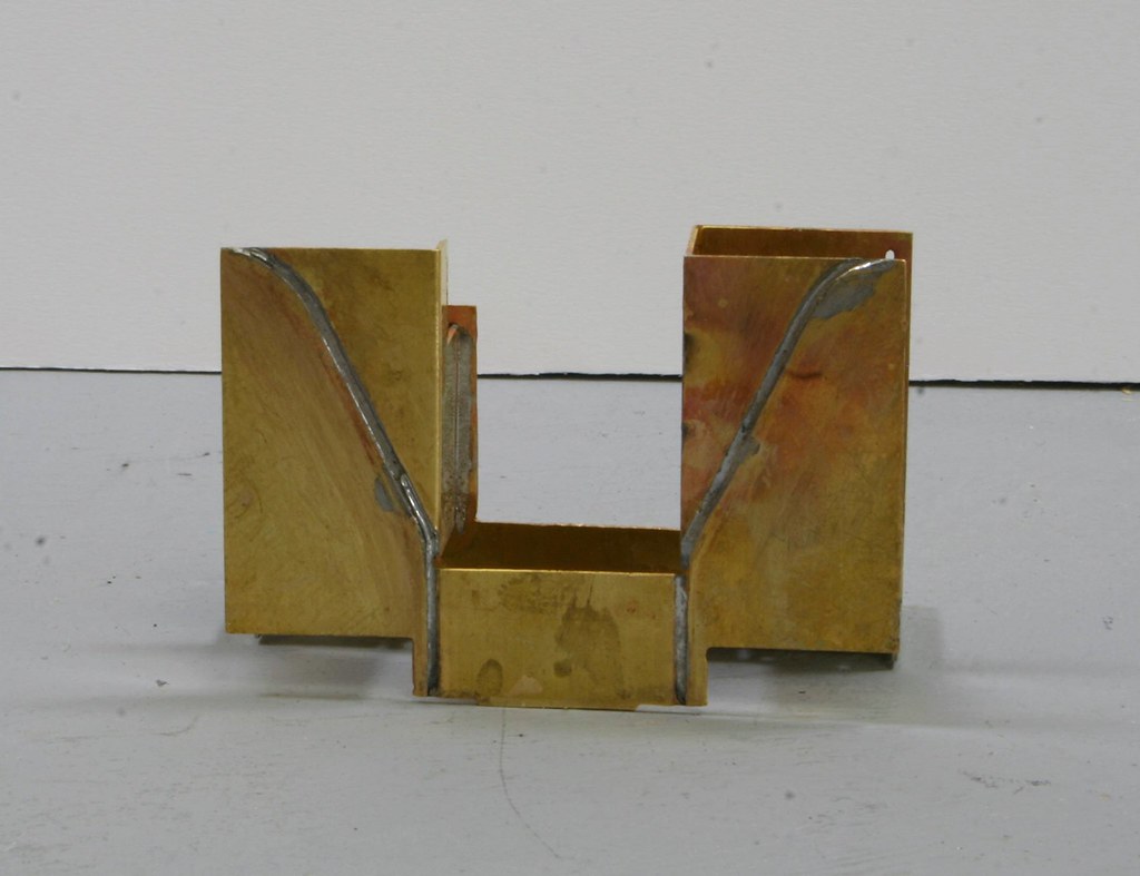
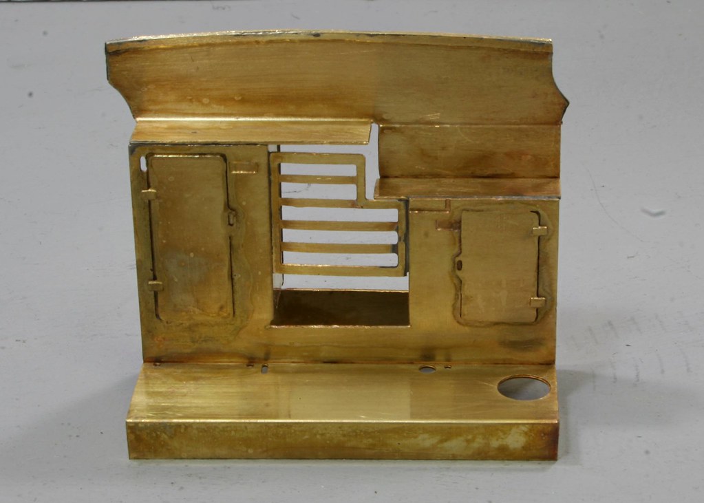
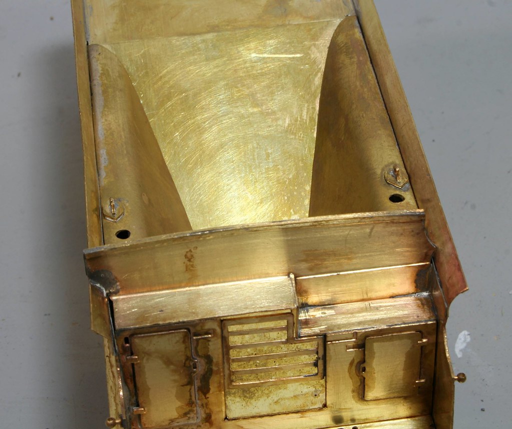
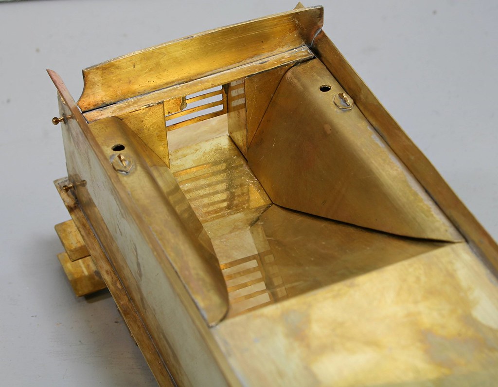
Firstly what the kit looks like:
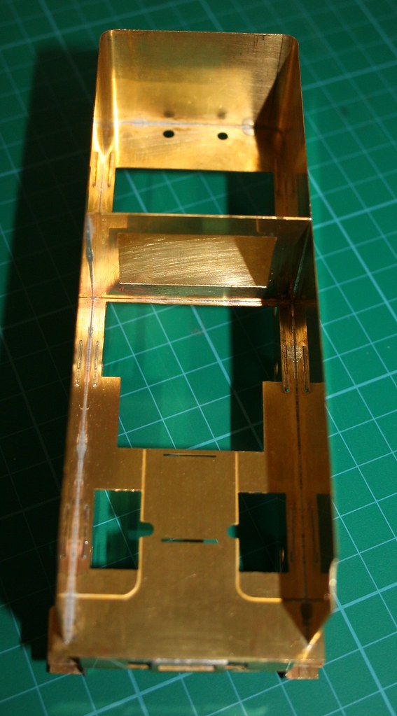
Next the tender attached to the Large Atlantic
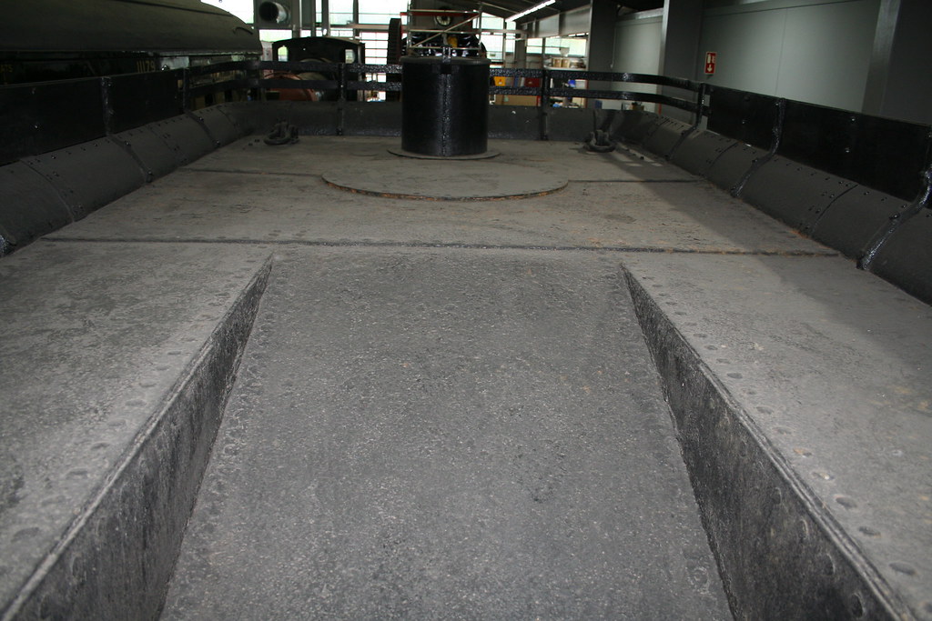
I have more detailed photos of the tender top on my Flickr site but these will suffice to tell the story to date.
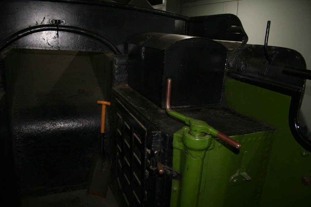
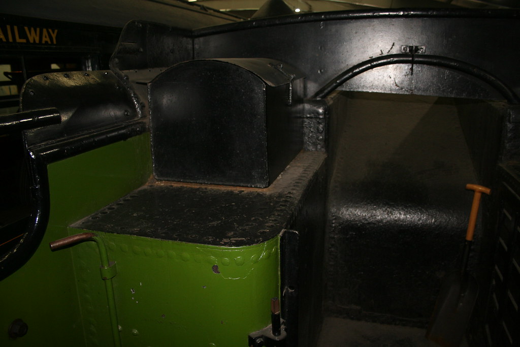
Lastly the tender attached to Henry Oakley and the one which I believe that I need for the J6 when compared to the couple of photos I have of the prototype – no 64206 and more importantly the type that I believe the kit is meant to represent (unless there was a third type which looked externally the same.
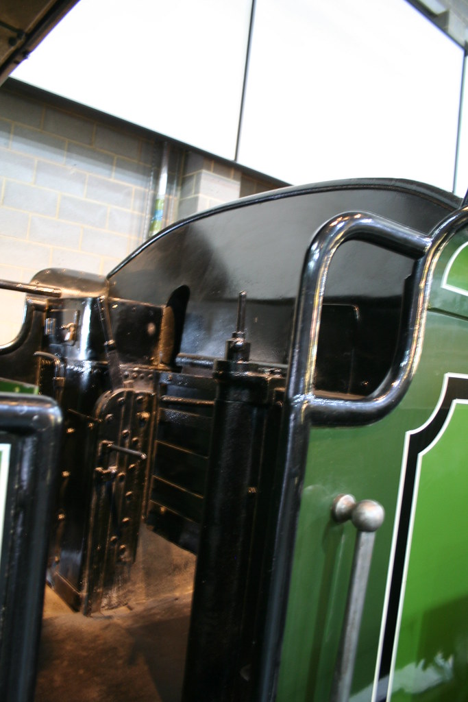

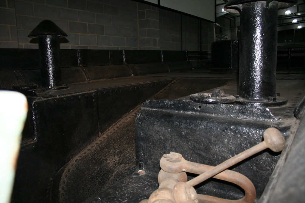
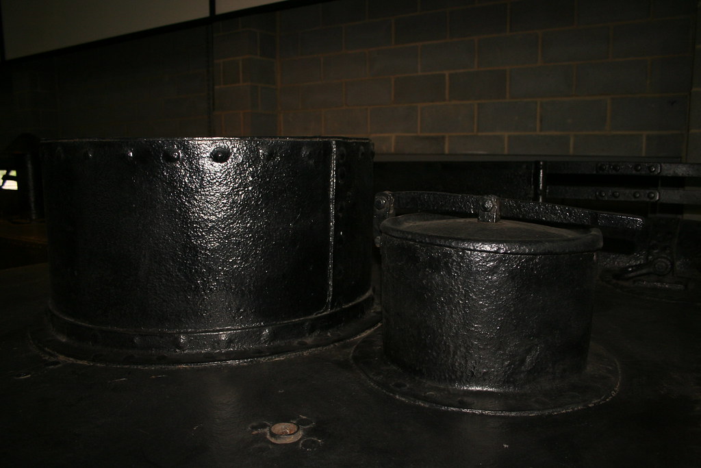
As I said, not the best photos but they do show that one side is higher than the other and there is a representation of lockers albeit the prototype show a small door on the higher side whereas the etch has a full height door. The key difference though is in the coal space. Both types of tender have a parallel rather plain functional coal space and I would be surprised if there was a third type that had one with the sloping sides that are inferred by the etches. I think that Malcolm Crawley got it wrong when he designed the tender kit but I would be happy to be corrected in that assumption.
Unless some evidence comes to the fore fairly soon to tell me that I am wrong I intend to modify the coal space to be more like that of the tender attached to Henry Oakely.
Regards Rob
Posted
Full Member
This has proven a very interesting side trip into the world of tenders from which I have learned a lot. I must also offer an apology to the late Malcolm Crawley for remotely suggesting that he might have had it wrong….
More progress to come as it happens
 Last edit: by Rob Pulham
Regards Rob
Posted
Full Member
I soldered some scrap etch into each side of the front step of the tender and sods law dictates now that I have I will find suitable parts included (I confess that I didn't even check).
It's all dry fitted at this point and before soldering I do need to check that the tank vents will fit - I may have to straighten the curve a bit to create a flat ledge for the vents to sit on but if I do I will report back.
Regards Rob
Posted
Full Member
Regards Rob
Posted
Full Member
Regards Rob
Posted
Full Member
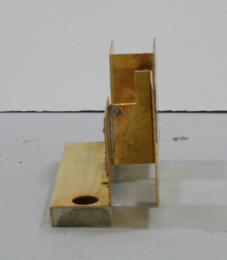
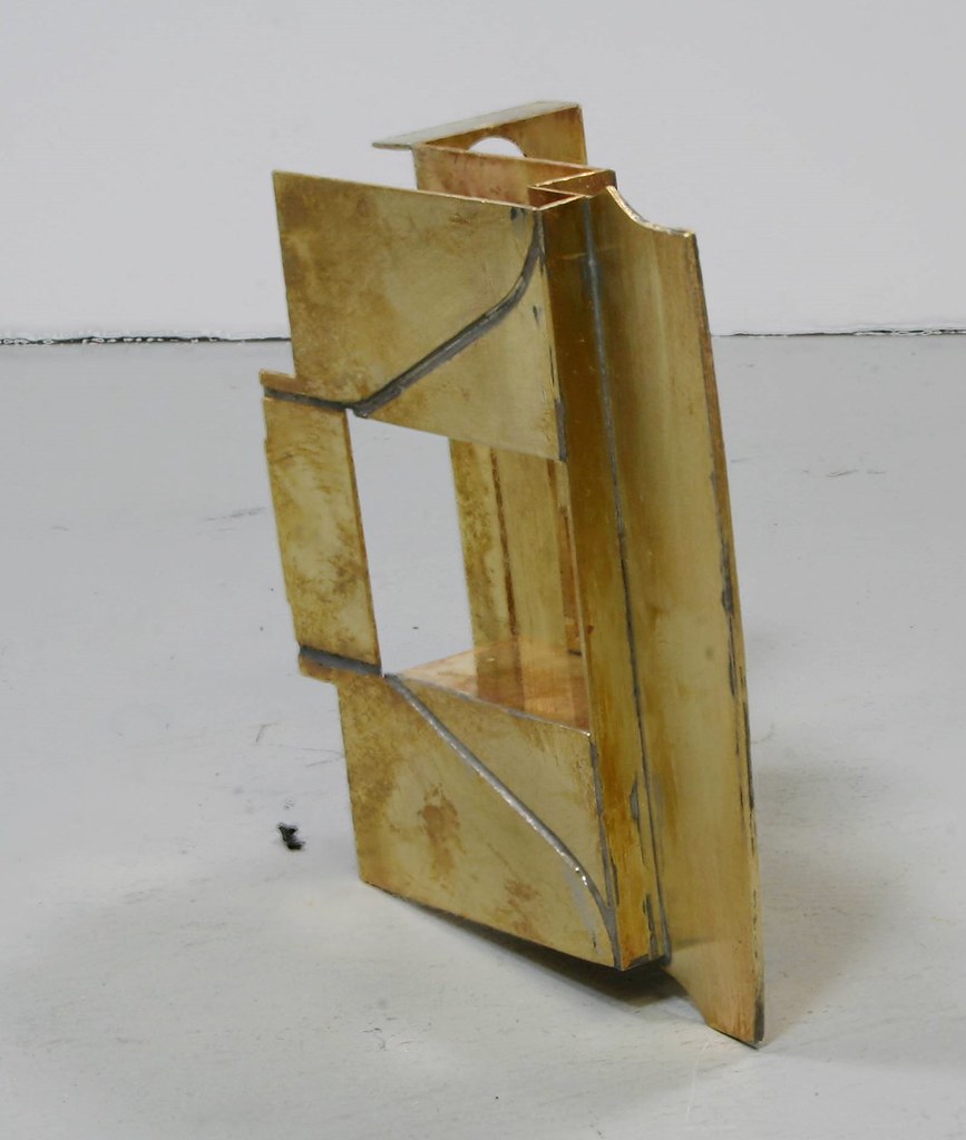
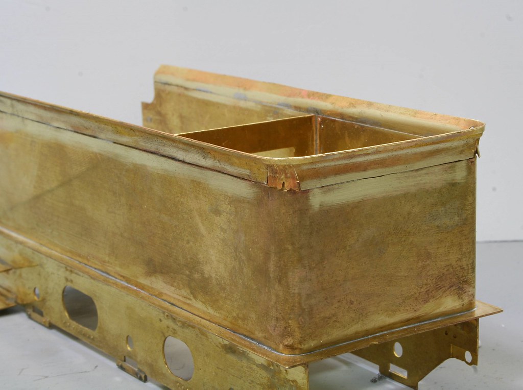
The reason for the slow approach has been a combination of a lot of other things intruding and the fact that I couldn't get my head around how the front coal plate shown in the last post attached to the tender front itself. While I pondered I moved along by fitting hand rail knobs to the tender sides and fitting lifting rings to the coal space sides and tank top/coal chute. I still haven't assembled the innards because I want all the sub assemblies ready and to have an understand of how things fit before committing myself.
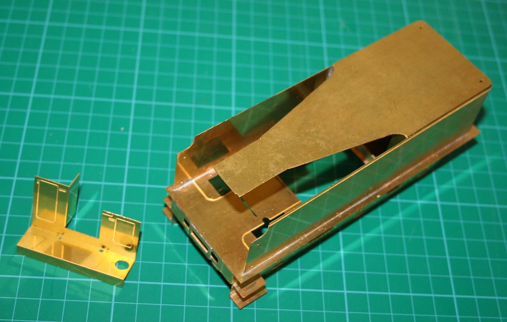
Before getting started on anything last night I re-read the instructions and saw the wood for the trees and ended up with this. Still a bit more to do but I am happy with progress.
There is mention in the instructions of a strip 49mm (I think but I don't have the instructions to hand so I will edit the post later and confirm) x 4.5mm
but I couldn't find the part so I used a suitable piece of scrap etch to make the infill piece for the back which forms a shelf behind the coal plate.
Lastly although not needed for my build but needed for the revision of the instructions I made up the two dome options which are included a rectangular combined dome/filler and the separate dome.
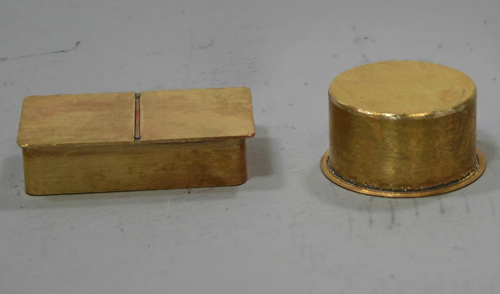
On the round dome everything was a perfect fit whereas on the combined dome I had to take a sliver of the two half etched overlaps to get them to meet squarely a simple exercise that took moments to do with a pair of topiary scissors

Regards Rob
Posted
Full Member
I only got part of it soldered on before bed time last night so tonight I will finish that and then take photos.
Regards Rob
Posted

Full Member
Just caught up with this thread and wanted to let you know that I am very impressed with what you are doing.
:thumbs
Posted
Full Member
Regards Rob
Posted
Full Member
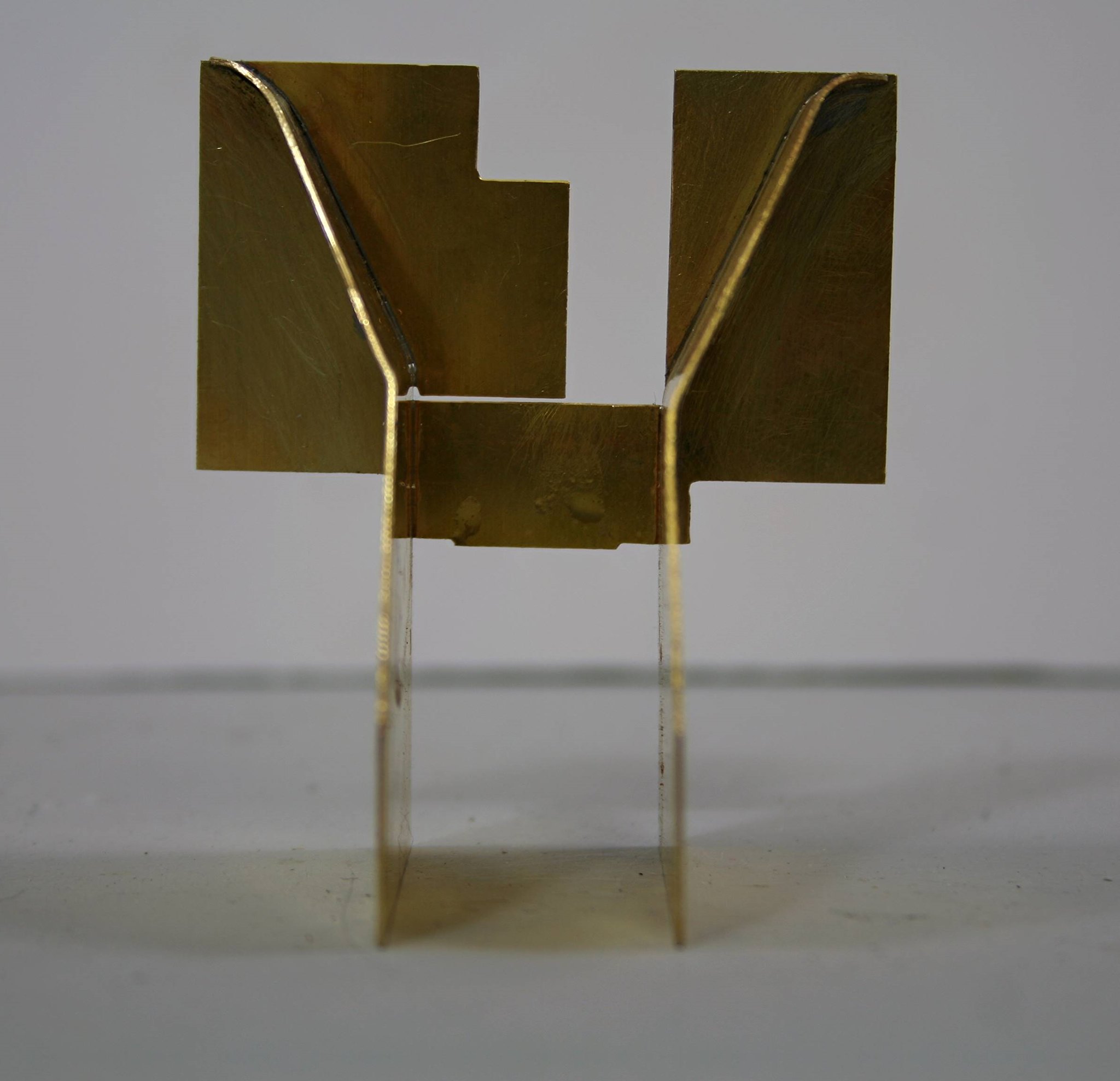
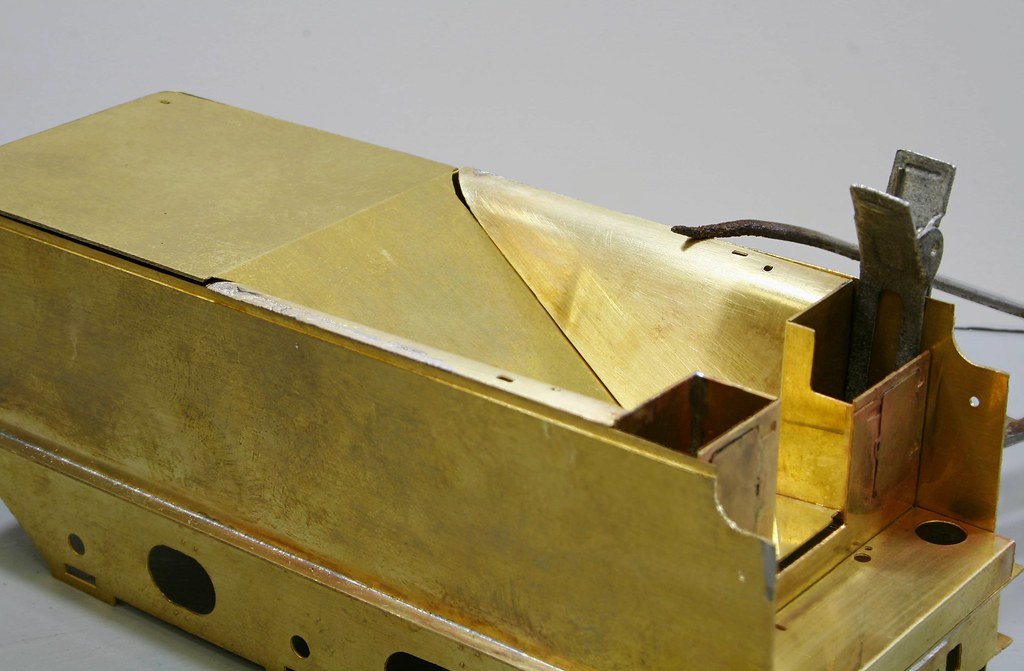
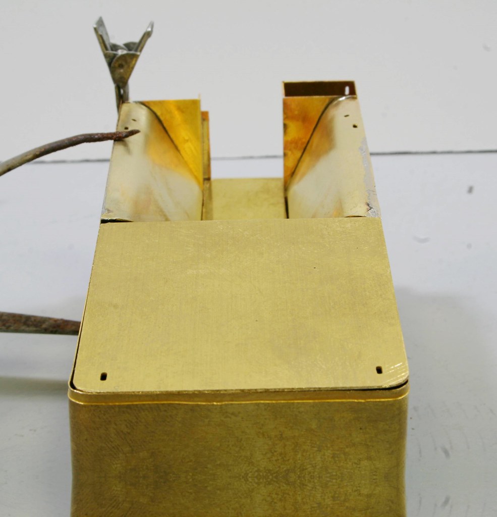
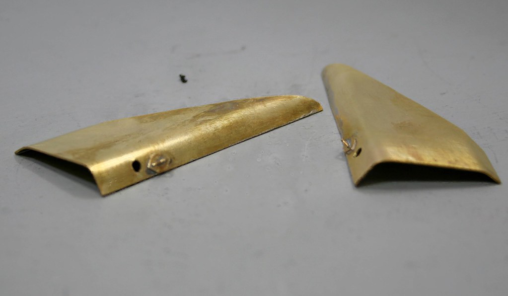
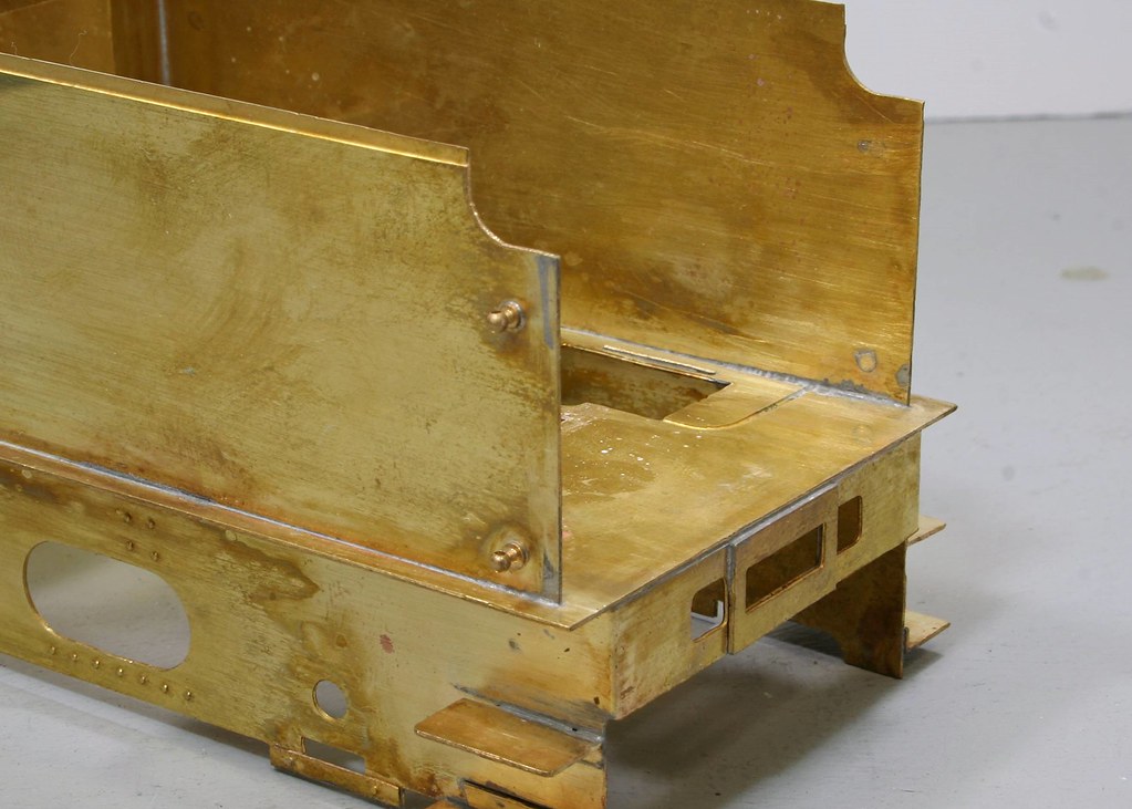
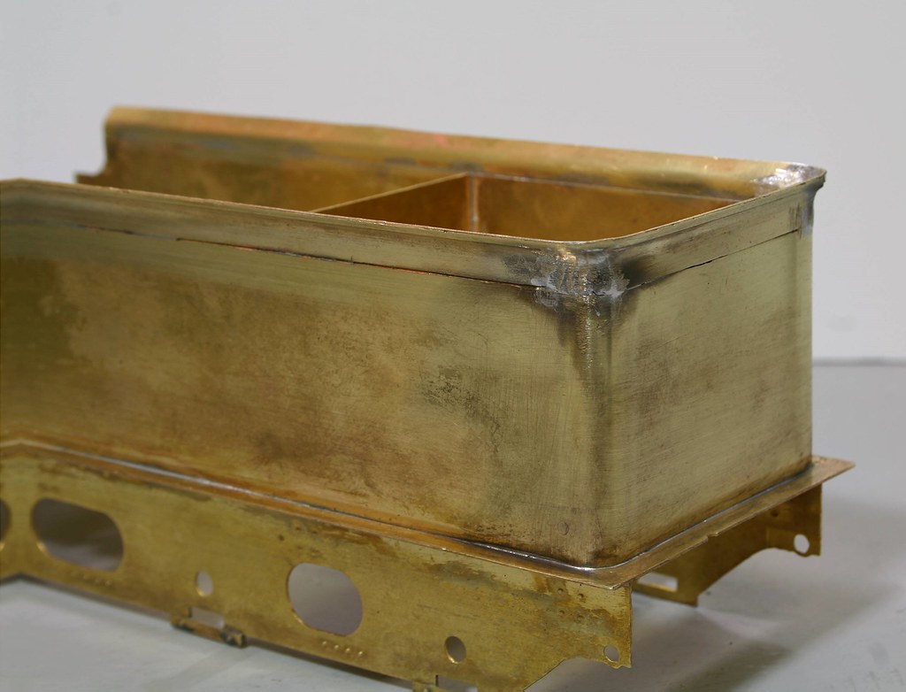
Starting with some shots after soldering on the flares but before starting to filling the corners with solder.
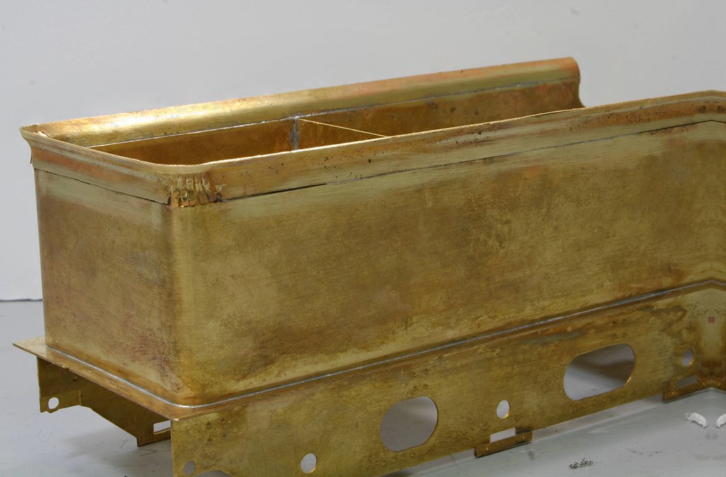
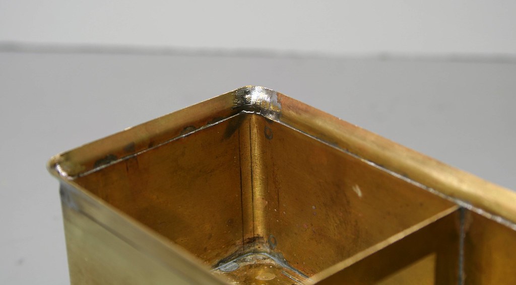
Then with the mostly filled in corners.
If they are of interest I also took a series of photos of my using my Proxxon vice with one soft jaw fitted to bend the curves on the flare strips.
Regards Rob
Posted
Full Member
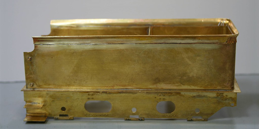
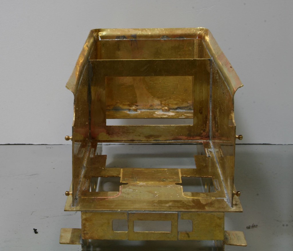
The coal plate is now in as is the front section of the tender.
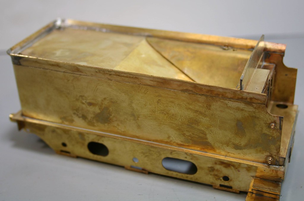
There is still a goodly amount of cleaning up to do and the sides of the coal space are still to solder in but I feel that I have broken it's back now.
Regards Rob
1 guest and 0 members have just viewed this.