Braughing to Standon branch design for N gauge
Posted
Full Member
I guess being an electrician by trade, a) it makes it easier for me to understand and b) I run a risk of using some trade shorthand when describing what to do as I think I did but you seem to have got through that! Well Done Mate!
Looking forward to more pix of the progress!
Cheers
Trevor

Posted

Full Member
Are they like like dead sections between lengths of track?? Best wishes. Kevin
 Last edit: by Passed Driver
Staying on the thread Kevin.
Posted
Full Member
Have you actually put up a plan? It is a bit hard to work out what block you may or may not need! I read in a couple of other posts that you have trouble reducing your photos etc. If you want to send the entire photo, I can reduce it for you using Thumbs Plus or GIMP that will enable you to upload it! PM me if you want my email!
Block work is not hard, although I can see that to a non electrician, the wiring diagrams seem a bit daunting. I suggest you have a read of the thread that Ken started on
http://yourmodelrailway.net/view_topic.php?id=9970&forum_id=21&page=1
but he overcame the trepidation of the wiring process and made a very creditable job of it!
If you are going with DCC, you only have to make your blocks as such that all the track is powered and there are no short circuits caused by electrofrogs. So perhaps a plan would work OK.
If you are not using DCC, then the most onerous task you need to undertake is to work out what your operating scheme is likely to be and what you want your trains to be able to do. The blocking will then fall into place!
Cheers from the Antipodes! ;)
Trevor
Posted
Full Member
Staying on the thread Kevin.
Posted
Full Member
I'm sure the admins of this site can help do that for you and also move the last few postings from my Braughing to Standon branch design thread into it too.
Cheers and good luck with the layout
Paul
Posted
Full Member
Staying on the thread Kevin.
Posted
Full Member
I have drawn my interpretation of Kevins layout showing a sector plate. I have only used one track of the sector plate as the Programming Track that can be changed to a DCC track.
I have a little bit of direct experience with DCC so the diagram was based on a few presumptions.
I have drawn insulators in the event that your frogs are electro frogs and need insulated joiners. The sidings are continuously connected. If you use Insul frogs, you can keep the wires but no need to worry about the insulated joiners.
DCC engines that are stabled are totally inert so it does not matter which way or where the engines are parked.
Programming Tracks need to be isolated so I have used one of the transfer tracks as the part time program track.
The DPDT switch determines whether the third track is the programming track or operating part of the layout..
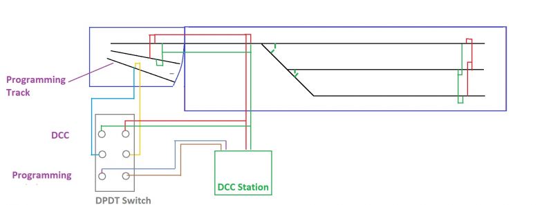
Hope this Helps
Regards
Trevor
Posted
Full Member
Of course I haven’t tried this , but it sounds good. Best wishes. Kevin
Staying on the thread Kevin.
Posted
Full Member
WIth Insulated joiners with the track, you can either remove that sleeper entirely or undercut it so there is an appropriate notch out of the sleeper under the rail.
Alternatively you can install a metal joiner at the point/turnout then cut a gap in the rail with a razor saw and super glue an offcut of styrene sheet (plastic lid from a margarine container or similar will do) and trim it to shape after it has definitely taken.
Hope that helps
Regards
Trevor
Posted

Site staff
Kevin. because I use flex track & remove some sleepers due to the curvature, I then remove part of the sleeper that is under the rail so that it does not interfere with insulated joiners - basically the concept that Trevor talks about in his first paragraph.Hello Kevin and any one else who might be interested,
WIth Insulated joiners with the track, you can either remove that sleeper entirely or undercut it so there is an appropriate notch out of the sleeper under the rail.
Alternatively you can install a metal joiner at the point/turnout then cut a gap in the rail with a razor saw and super glue an offcut of styrene sheet (plastic lid from a margarine container or similar will do) and trim it to shape after it has definitely taken.
Hope that helps
Regards
Trevor
Ron
NCE DCC ; 00 scale UK outline.
NCE DCC ; 00 scale UK outline.
Posted
Full Member
Staying on the thread Kevin.
Posted
Full Member
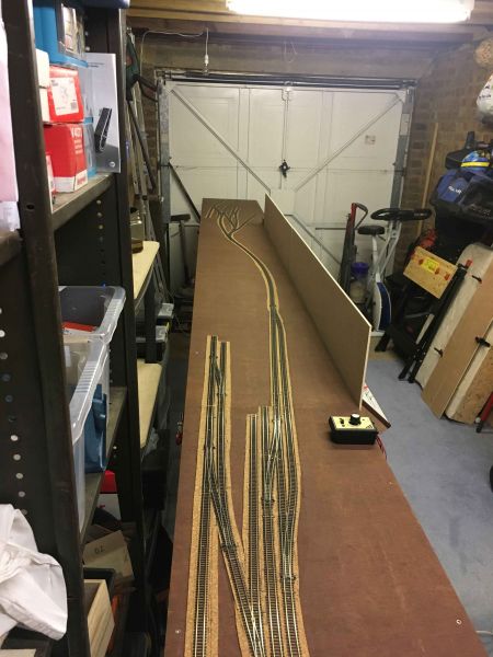
Latest update - all soldering of drop wires (common and live) complete as are the turnout frog 'livening' wires. Also complete are the holes drilled for all point switching ready to receive the SEEP point motor operating rods - currently looks like red, black and green spaghetti under the modules but overall very happy how its all turning out. Have also fully tested all the operating modes (isolating areas, mimicking the block sections being powered on / off manually) with two locos and I cannot find any dead track areas or issues … so even more happy about that - especially as it means I fully understood all the instruction and diagram help Trevor provided.
Next step is finally to tack down the track to the baseboards so everything is fully solid and firm - then I will disconnect a module at a time and work on it on its side at a nice height on the workbench to fit and solder all the SEEP point motors. I've also created 'under side' layout plans of the wiring so far with numbering for all the droppers and frog livening wires - I'll place small number stickers to the underside as reference for anybody else to understand what each wire provides to the layout and where it is located (especially as when the ballast is finally in place and the wire connections to the track are hidden) - done with my son and grandson in mind for the future when they inherit the layout and I'm no longer around.
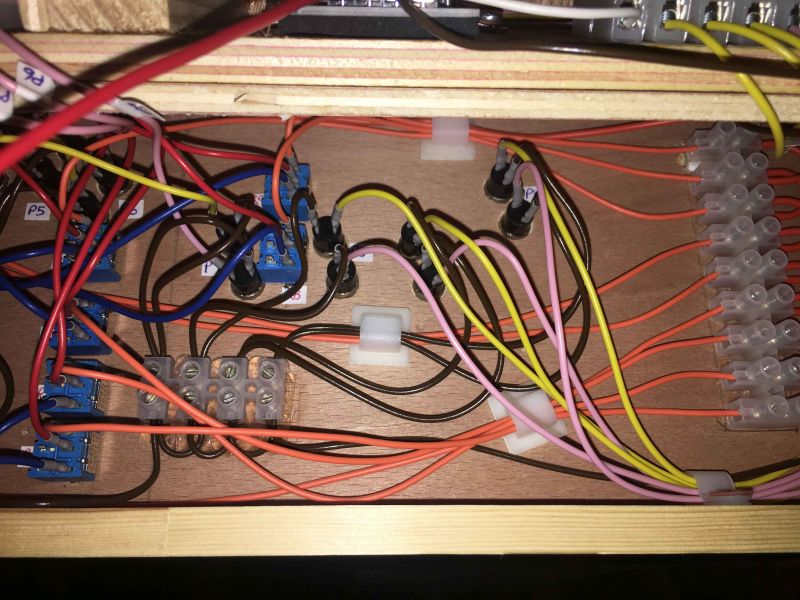
At the same time I'm diagramming the Controllers (CAB Control) wiring for blocks based on an earlier example I interpreted from Trevor's hints once again, only this time its for the whole layout as one. I have attached this below as I have perhaps a silly question if one of you can help. BTW … its not fully complete yet.
For reference:

And now the question based on the zoomed in section:

Black Wire = common feeding both Controllers.
Red Wire = live feed from Controller 1 (shown in image) to block switch.
Blue Wire = live feed from Controller 2 (out of shot at the other end of the layout) to block switch.
Green Wire = live feed from block switch to track section.
Question:- there is only an operational desire for Controller 2 (blue wire) to be able to power / move a train to certain parts of this end of the layout (West station) so I have only indicated it be connected to certain block switches, namely 1,2 & 3. I can see no reason why this should not be done from an electrical perspective, other than perhaps requiring single on/off switches for these - is that correct?
I also intend to apply the same methodology at the other end of the layout (East station)
cheers
Paul
Posted
Full Member
Theoretically there is no problem with what you envisage doing and it will be easy enough with centre off switches. You will not have an issue with using the same switches throughout so no need for a separate On/Off switch.
I can see where you would have local control for the yard at the West and East Ends of your layout and there is no problem with that, my issue is with flexibility for later on where one operator can play the shunter while the other drives from either end of the layout or where there are two trains at one end.
Using the West Station as the benchmark, are East bound goods trains made up and dispatched on the main line passing siding or in the goods yard sidings? For the East Station, will Goods trains pull in then back up into the yard which faces "further east"?
In either case that train will then need to be taken over by the appropriate station throttle before it can do anything else which may be as you want it. For the want of a few inches of wire, that flexibility will be markedly improved to my way of thinking.
As you would know, my throttles are home made and I have had issues mainly with the walkaround version from time to time with the portability and the inherent ability to drop it causing an internal malfuction. At least I have been able to continue operating with a contingency plan with the other two while undertaking repairs or locating parts etc.
By isolating some sections to one controller, you would be cutting out that aspect of your operation in the event of a similar problem, as rare as that may be.
But it is your railway and you need to do as you see fit - and in any case good luck with it. As an aside, I will be indisposed for a few days at least with surgery tomorrow so dependng on when you reply, you might not receive a reply for a while. But I am looking forward to seeing the progress when things improve!
Regards from Australia
Trevor
Last edit: by xdford
Posted
Full Member
Have just completed some more testing of track connections and switch / point simulations and I still can't break anything so I consider it to be as sound as I can make it - if something does crop up once the track is fixed I'll just have to fix it. Plan is to start fixing the track as described in previous post over the weekend, taking my time.
I hope the surgery is not too serious and of the more minor type - hope all goes smoothly and wish you a fast recovery back to normal.
Sincere regards
Paul
Posted
Full Member
Well, although this thread has not been updated since August last year, I have been busy with all the wiring, D-Sub fitting, manufacturing my own 16/02 D-Sub cables and building / wiring/ testing two control panels. A lot of what I have been working on through Autumn and part of Winter can been seen on my thread "Track power connections across baseboard modules" http://yourmodelrailway.net/view_topic.php?id=15440&forum_id=6]
I have now fully tested full operation of the whole layout (all 4 modules connected, control panels connected) with 3 trains (2 shunters and a DMU) in the intended mode of operation … any everything works perfectly, including all the power isolation blocks and CAB control (2 controllers able to operate the shunters and DMU for the whole length of the layout as required). I did take my time and made detailed diagrams as I went and tested each step of the way - there were not too many teething troubles at all really but this was in the main thanks to the great advice and electrical diagrams provided by Trevor and also advice from Ron …. can't thank you guys enough.
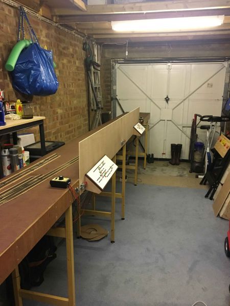
So, I now have 2 modules fitted with my desired scenic back board size and the control panels mounted .. the last two modules I'll b]make a start on the same this week. After that, its ballast time and then fitting the platforms at both Braughing and Standon ends of the layout … then an orderly plan to tackle all the scenics and station. buildings, etc ,etc. Its going to be a busy Spring !!
Here are some photos of the control panels and the layout in full situ - it may not much but I can assure you the underside of the modules hides all the recent months work (putting in spare time hours whenever I can)
With control panels in view
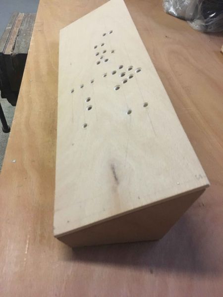
Control panel construction - holes for point switches (smaller ones) and power isolation switches (larger ones) marked, drilled and counter sunk.
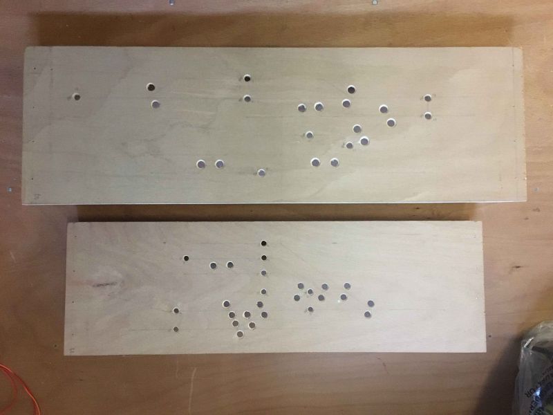
Side view of the construction - mostly all in 6mm plywood with some 18mm soft wood .
Underside showing construction and labelling
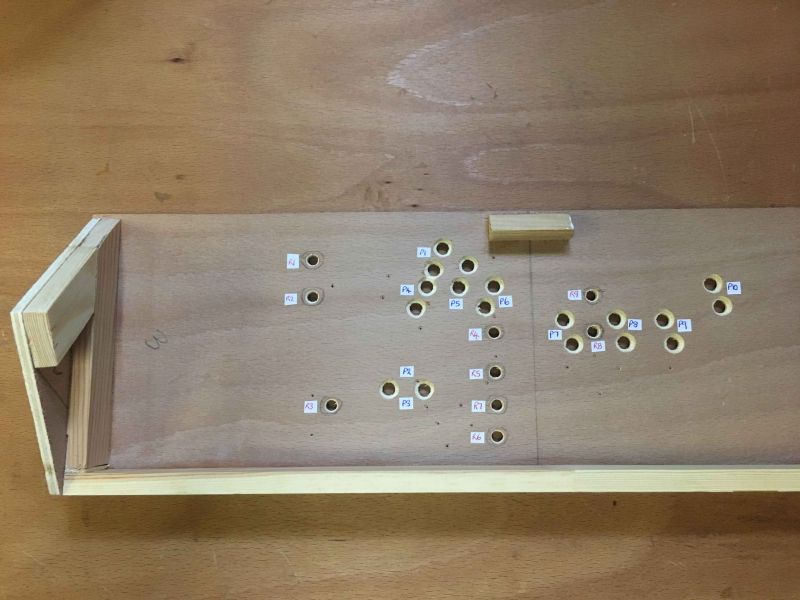
Covered with white sticky-back plastic for easy wiping of dust and dirt, plus smart appearance. Holes cut out steadily with a very sharp craft knife.

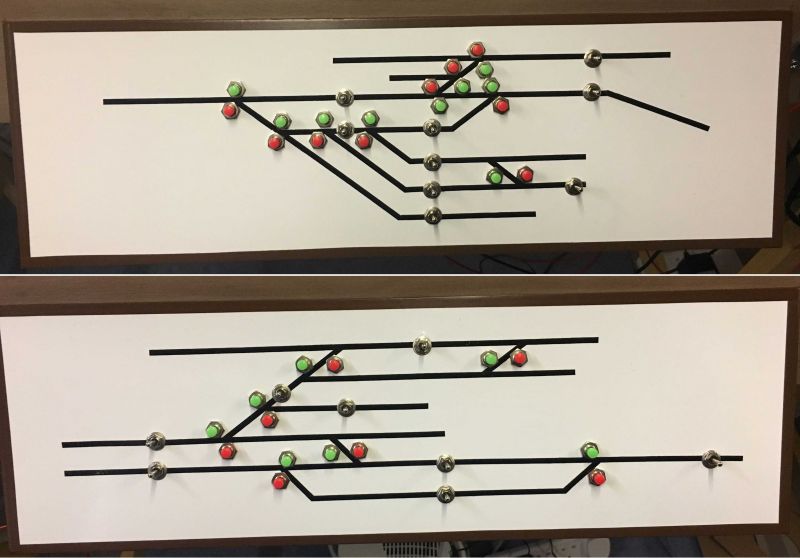
The finished items - black nobo-board sticky lining, cut and shaped, used to indicate the main layout. Push to Make switches used for all points (green for the main branch & siding loops, red for the small sidings / head shunts), DPDT mini toggle switches used for the power isolating blocks which also allows CAB control, edges lined with brown electrical tape (very sticky) for a neat finish. Standon control panel on top, Braughing control panel below.
Underside of control panel - again trying to keep everything neat, labelled and easy to access for wiring issues or swap out any faulty switches.
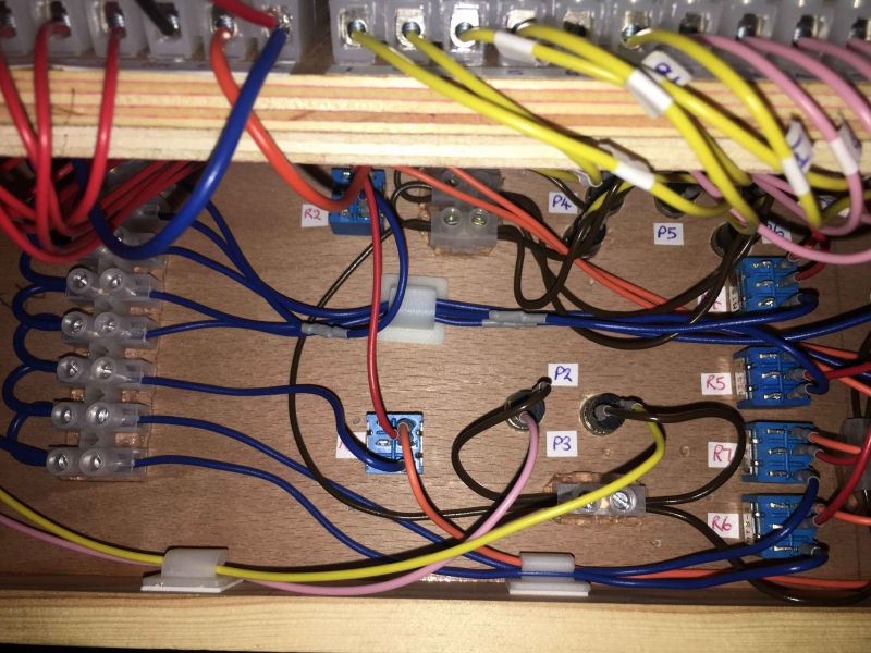
Another view of a control panel underside.
Keep you posted as the scenics progress,
cheers
Paul
Last edit: by Padster
Posted

Full Member
Watching with interest.
Best,
Bill
At 6'4'', Bill is a tall chap, then again, when horizontal he is rather long and people often used to trip over him! . . . and so a nickname was born :)
Posted
Full Member

Oh well back to the asylum
Posted
Full Member
In fact, I also maintain and populate the society's Buntingford website and scan / post all the photos too - if you have not seen the website take a look http://www.thebunt.co.uk/index.html and check out the 'gallery' & 'now & then' sections where there are many more photos of Westmill.
Very interesting to hear that you have a direct connection to Westmill via your late father-in-law and partners Grandfather. I'd also be very interested to hear of any other photos or memorabilia your family may still possess of Westmill that we could share on the website, with permission of course - I'll send you my email address via a PM so we can converse a little more on the topic.
All regards
Paul
Posted
Full Member
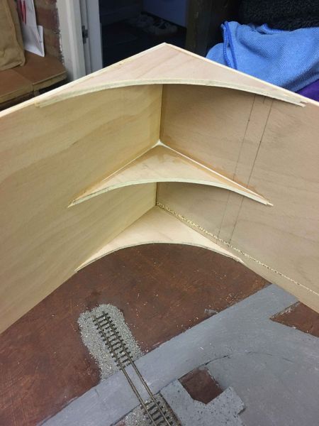
Update 1. Backscene
My backboards are 12†depth; 4†fixed to the baseboard sides for strong fixing and 8†forming the actual backboard. They are made from 6mm plywood in 4 foot lengths and aligned across the complete 16 feet length of the layout.
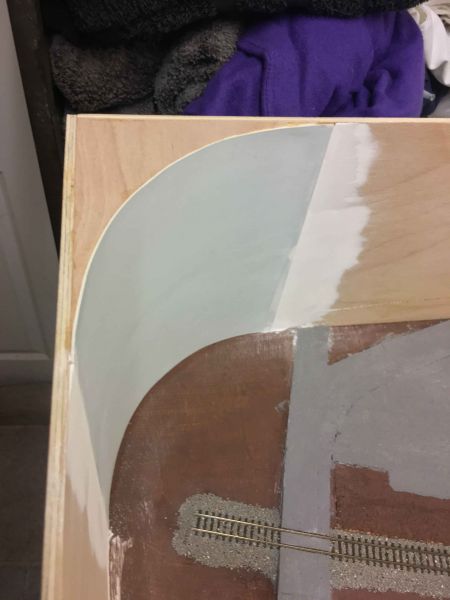
To give the layout a more ‘continued feel’ to the eye, I created curved rather than right angles corners, braced by top, middle & bottom curved edge supports onto which I glued 1.25mm Graduate Blue card to form the corner curve itself. To ensure the card edges were smooth where joining the plywood baseboard, I used fine Polyfilla.
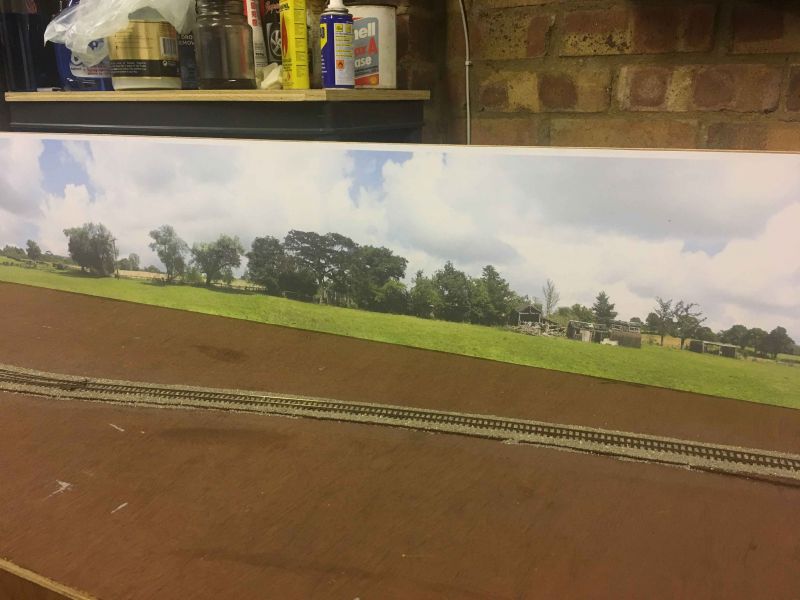
I wanted a low horizon eye line to compliment the length of the layout & I preferred a realistic photographic backscenes rather than a painted one … also because I had seen various great layouts that used such low level and photographic backscenes to great effect in N gauge end-to-end style layouts. After much research I opted for the ID BackScenes ‘Into the Town’ pack B which came in 2 sections of 5 foot x 9 inches and costs around £10. For my layout I needed two of these packs but they all joined together quite seamlessly. The quality is very good and they are printed on 180gsm paper so are borderline card.
After much aligning, double checking & measuring the backscenes and trimming the bottom to reduce the height down to 8 inches (leaving the small white border at the top – purely my choice as it seemed to set up the backscene nicely) I was ready to start gluing them into place .. hold my breath and nerve – again this was a first for me.
I bought some Deluxe Materials View Glue which is supposedly to be designed especially for backscene adhesion. I decided to test gluing some backscene offcuts onto plywood offcuts, using both PVA glue and View Glue. To be honest, both did a good job with good adhesion and no wrinkles nor air bubbles. My own impression was that the View Glue dried quicker and fixed in place sooner compared to PVA glue. Based on these tests I went ahead with preparing to use View Glue but a key point to note is this – the ID Backscenes recommendation is to apply your chosen adhesive to the backboards, use the least amount of glue you can and that is was not necessary to cover all the backboard area with glue… however the View Glue instructions generally state to apply sufficient glue to the backscene paper itself and then position up to the backboard and roll smoothly into place. As these instructions were contradictory in advice I researched further on various forums for real world experience with these products and in the end I opted for the approach as follows.
- I used View Glue sufficiently spread across a whole baseboard 4 ft section at a time, working quite fast.
- Lined up the backscene from the left, smoothing across to the right with the edge of my hand.
- Using a dry cloth, gently smoothing further from left to right checking that all alignments top, left, right, bottom were good.
- Checked the top, left, right and bottom to ensure these edges had strong adhesion, adding extra glue with a small size artist brush if required.
- Any small bubbles were left – these disappeared overnight as the 180gsm paper dried and pulled tight.
- On only the 3rd section of 4 ft backboard length I decided to try just adding View Glue along the top, middle and bottom in 2.5 inch strips of glue, so to speak, leaving the gaps in-between glue less (this was to try the recommendation given by ID Backscenes hint sheet supplied in the pack B). After a few days all looked good but once the weather started to get cooler and colder in the garage, I noticed that non-glued areas where lifting somewhat – not totally noticeable to the human eye but most certainly to the touch. For this section I tried to make repairs used a damn cloth to moisten the backscene paper and see if it would all dry tighter which worked in a couple of places but not in others. Biting the bullet, I had to replace this 3rd section backscene completely which was extra effort and another £10 but all worked out well in the end – lesson learned.

Conclusion using ID Backscene photographic paper and View Glue adhesive - overall result is very good and I’m very pleased but some small and unnoticeable areas are not fully stuck but tight enough to stay in place for a long time … it also helps that the ‘Into the Town’ pack B has a lot of sky and clouds which greatly helps disguise any small bubbles or unstuck areas you may get. With View Glue you MUST work fast as I found it does not remain workable for any re-positioning for any real length of time. I certainly recommend to cover the area of baseboard you’re working on with glue and not leave any gaps or you are quite likely to see (or feel) parts that are not stuck. I also recommend to work in 12†sections of glue, align and smooth then move onto the next 12†section, and so on – this seems to be the best way to get the best alignment and adhesion … even though I did get away with gluing a complete 4 foot section and getting the alignment correct and smooth finish but perhaps that was just luck.
Lastly, these are purely my own views and experiences of the products used and my own methods for a finished result.
Thanks for reading
Paul
Posted

Full Member
Cheers,
Claus
www.flickr.com/photos/ellef/
Claus
www.flickr.com/photos/ellef/
1 guest and 0 members have just viewed this.