Braughing to Standon branch design for N gauge
Posted
Full Member
The extra switches that I was referring to are here
https://www.ebay.com.au/itm/10x-Mini-Momentary-Push-Button-Switch-On-Off-for-Model-Railway-Hobby-Red/121642121608?epid=1589805138&hash=item1c526f7988:g:YzgAAOSwdW9aNASS
You may have to access these from fleabay in the UK to see what your price will be…
Also studying it further, you will need one insulator on your mainline between the east and west station as you have two switches feeding the same block… presumably the joiner will be at the join of the baseboards.
Cheers
Trevor
 Last edit: by xdford

Posted
Full Member
I'll be using electro-frogs so as I understand it i must add IRJ's on each after the frog point - see below.

I can also see I made a mistake in mentioning the centre off switches for the points … they will be used for the section blocks actually which I believe will be ok.
Cheers
Paul
Posted
Full Member
Posted
Full Member
You will essentially need insulated joiners on both roads at every point possible so I will get to it with the diagram… it will mean a little more soldering and wire connections but it presents no major problems!
Expect it within a day or two…
I had a link to using cheesehead screws rather than switches … check out http://yourmodelrailway.net/view_topic.php?id=12852&forum_id=21&highlight=%26quot%3BCDU%26quot%3B+and+%26quot%3BProbe%26quot%3B#p227065 which may be of interest to!
BTW Ken's diagrams which I drew for him show the use of electrofrogs and common rail! It is at http://yourmodelrailway.net/view_topic.php?id=9494&forum_id=6&highlight=%26quot%3Bwiring+diagram%26quot%3B+and+%26quot%3BKen%26quot%3B#p180539
Regards
Trevor
Last edit: by xdford
Posted
Full Member
While waiting for some paint to dry and the wife to come home from Exercise class, I started studying the plan and I feel you may need more switches for control purposes… even if it is only switching an area such as the head shunt to the left of the catch point.
If you want (read… need) extra switches, you may as well set it up as an electrical block as I initially did for two operators and rely on the centre off position of the block switch… in fact it should be easier, although a taking a little longer!
Let me know what you would like to do!
Trevor
Posted
Full Member
The links you also sent previous to older diagrams you devised were also very helpful … as indeed is all your shared knowledge.
cheers
Paul
Posted
Full Member
Essentially replacing those rotary switches with DPDT switches is OK as you have noticed but the insulator positions need to be defined.
If you could let me know which "blocking" you are OK with and I will rework the diagram for insulators and feeders from that,
Cheers
Trevor
Posted
Full Member
Thank you
Paul
Posted
Full Member
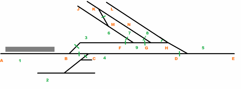
Paul (and anyone else) if you could check the insulators and see if there are apparent conflicts with power through given points please bearing in mind that the frogs are live. I have designated blocks using numbers and location points using letters without the wires in place in this diagram for clarity purposes.
Cheers
Trevor
Last edit: by xdford
Posted
Full Member
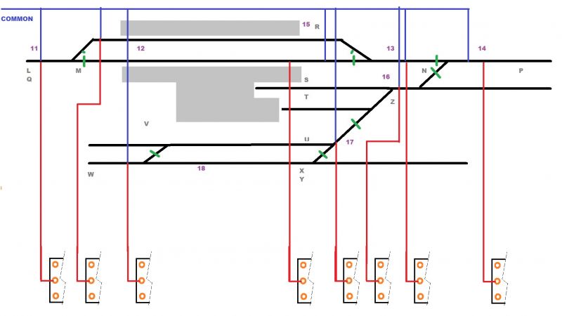
While I have shown the common rail to appear long in its connectors, you only need droppers to go through the board with enough of a tail to join a wire running under your board (so it will be physically closer than the schematic suggests)
Anyway here it is (with the modification suggested in my next post)

Hope this gets you through the first bit!
Cheers
Trevor
Last edit: by xdford
Posted
Full Member
Thank you kindly from the Northern Hem
Posted
Full Member
Shucks Mate!!! I feel quite flattered but I have already found a minor goof in that I have put in a common connection to the mainline at the passing siding at both F and H but you only need one of these. The best laid plans… I have updated it on the posting!
Given my druthers, I too would have used electrofrogs myself on my own layout as some of the insulfrogs have worn down over a period so no you have not done the wrong thing! The setting up of the switches will go quicker than you will have thought at the time you come to do it and following the techniques that Ken used, you should have little problem.
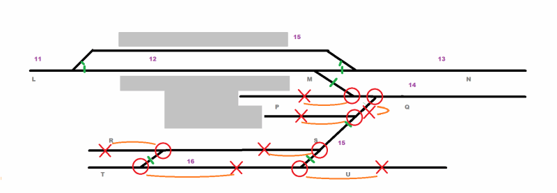
I will get an East Station diagram done for you soon but there will be a slight issue with which point layout you are going with? The actual track diagram or the modellers licence one? The former will give you the "accurate" model, the other will make operations a bit easier for you. And it is your railway!
Cheers for now
Trevor
Last edit: by xdford
Posted
Full Member
This went a bit quicker than I thought
I have done the two versions of the East Station showing the insulated joiners. When seeing the operational possibilities, some areas could be isolated by using the electrofrogs with the point against the movement so I did not worry about the idea of too many blocks.
I have followed the Draftsmans alphabet by using the letters starting from L for the right side (East) of the layout but just check the insulators. As you will have realised, it is easy enough to make a change as we find issues.
A question however, did trains terminate in the "bay road" at the prototype of your station, viz not run the full length of the line?
Anyway here are the trial insulation points… check and see if they foul your idea of possible operations.
Regards
Trevor
Last edit: by xdford
Posted
Full Member
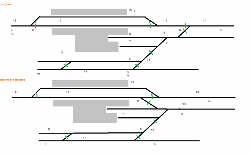
This should hopefully be the final diagrams barring any discovery of faulty design on my part for both options… I am relying in part for the electrofrog points in a similar mode to insulfrogs where it seemed to be appropriate but I am presupposing some of your shunting moves and general operation.
Anyway here they are,
The Original…
and the "Modellers Licence" version
Interestingly the accurate plan requires one more switch.
Hope this has been of help for more than just yourself Paul,
Cheers from Oz
Trevor
Posted
Full Member
Actually, I am sure others seeing these diagrams and following the thread - even non-members - will take great insight from the information. With the exception of some other threads on this site and Brian Lambert, it was this kind of really useful and clear diagrams I was finding it hard to find on the web - for novice electrical peeps this is a godsend.
On the topic of 'Original' vs 'Modellers licence' layout schema, you were 100% correct Trevor and it was the 'Modellers licence' version. It looks perfect for the operational aspects I had in mind and even negates me asking another question on some changes I had considered … only subtle ones mind but you already read my mind.
TBH I rechecked the original station plan copies I have of the whole of this branch line - and low and behold the original plans WERE as depicted in the 'Modellers Licence' … the real station layouts were changed a little around the 1950's I believe and that was how come my original layout design was based on that instead. So 'Modellers Licence' it is … and retaining its authenticity.
Your last question - "did trains terminate in the 'bay road' at the prototype of your station, viz not run the full length of the line?" If I understand you correctly, my planned operation will be the branch train will terminate at point 15 on your diagram (the down platform), then run on to point 13 in a visible fiddle, then return along to point 12 (the up platform) … then onward to the West station.
cheers
Paul
Last edit: by Padster
Posted
Full Member
Here's things so far … note: I've added extra cork underlay in places after these photos were taken, to ensure there is ample either side of the track.
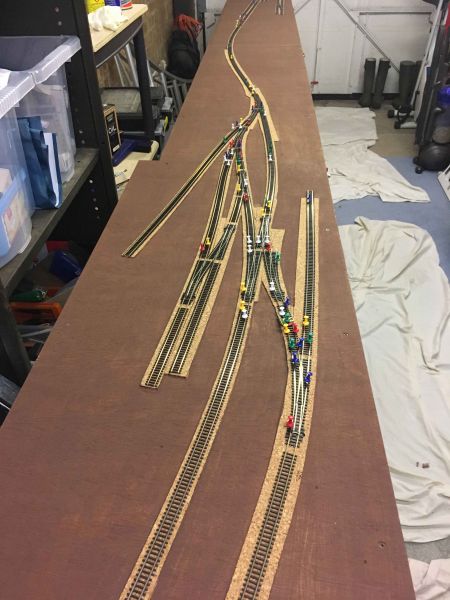
cheers
Paul
Posted
Full Member
Your order is pretty well right and it is your railway so you can do it in what ever order you feel comfortable with.
I don't know quite how you intend to check out your sections as you go (multi-meter?) but if I could suggest that you use small spikes to hold your track on the outside of the sleepers so your track is held in place, run the common line as I suggested then your droppers that will go to the switches.
However instead of connecting them directly to the switches, use a temporary runner wire to join up all your blocks and treat the whole layout as one block. I would suggest that you connect one wire to the runner at a time and ensure that the train will run. If there is a problem such as a short circuit , you can then disconnect one wire at a time until the problem is no longer there and you can locate the issue such as a misplaced IRJ or reversed wire etc.
Then run to your hearts content with backup, shunting, running etc at a reasonable rate of knots so that your trackwork is fairly "bomb proof" because testing in slow manner or pushing stock over the track is one thing, the actual operation is definitely another.
When you are OK that the track is performing well, then drop your PVA glue into place and lift the spikes when the glue has dried. You can then connect the wiring for the blocks to your control panel one at a time and check each switch as you go. Again check out Ken's pictures as they are almost text book examples of how to tackle the wiring.
Hope this helps,
Cheers from Oz
Trevor
Last edit: by xdford
Posted
Full Member
cheers
Paul
Posted
Full Member
As an after thought almost, when you connect the common rail, you could almost guarantee (notice I said …Almost) that you will be free of problems as far as short circuits are concerned with the following.
1. Before you start connecting the common return wires, check each section of track with a Multimeter to ensure that there is no short between the rails.
Using the diagram of Feb 24 and 25 You WILL have a short if you measure at the following Node areas (I am not using the word POINTS to avoid a bit of confusion) if the POINTS are set against the train at areas designated by the following nodes. I have use the "X" for the meter measuring point node and the "O" is the point which WILL appear to be a short circuit if it is against the train coming through. This is shown by the orange coloured link.
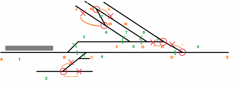
2. Once you have cleared any possibility of a short circuit, then check the continuity of the common rail. Length of your multimeter leads is not important as you can just check continuity from rail to rail in each section of the common rail and proceed along the length of your layout.
Then you should be able to put in the droppers and connect them to the temporary runner as I suggested in the last post.
Hope you are not the only one here that this is helping but it certainly got my thinking cap going!!
Cheers
Trevor
Posted
Full Member
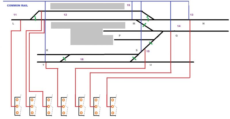
I made a goof … not a severe one but there will be a dead section in the original wiring plan which the following will illustrate… how come no one else picked it up????
Here is the original goof and its correction. The wiring diagram is essentially correct in its first version so it is only one Insulated Rail Joiner to be replaced with a metal one
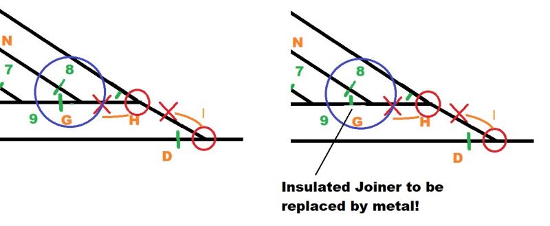
Sorry about the mistake … it was an honest oversight. Hopefully that is the only one!
Regards
Trevor
1 guest and 0 members have just viewed this.