Braughing to Standon branch design for N gauge
Posted
Full Member
Trevor

Posted
Full Member
Posted
Full Member
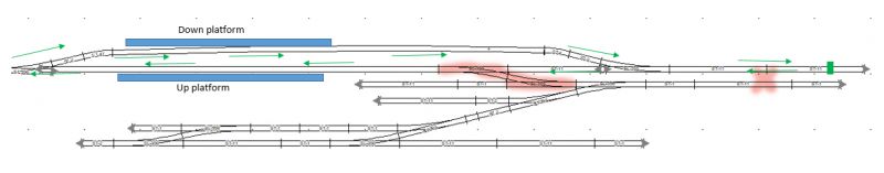
This is the schematic I think you should think about running with… It is quite late here so I will update it in the morning with the rationale

The idea is to be able to run your rail car into either platform 1 or 2 and isolate it while being able to either shunt at the East end or run through a train the length of the layout… of course this may be subject to change in the morning!
Cheers
Trevor
 Last edit: by xdford
Posted
Full Member
With a clearer head this morning, here are two types of switches you can apply to your control panel

They are of course very different physically but still electrically the same with 6 contacts at the bottom but the illustration I got was of centre off switches.
With the previous diagram, I toyed with the idea of on/off switches for the platform roads but I think it would have been a bit awkward to park the railcars then negotiate the freight runs around either road. I would take it that the railcar would sit on the platform with the ticket office while passengers exchanged across the bay platform? The way I have drawn it, a railcar can pull into either platform and be isolated with the switch at centre off!
Hope this makes sense to you and I have tried to keep up the flexibility as well as the "integrity" of your prototypes plan.
The idea of slanting the "East" station has another advantage for you in that not having lines parallel to the edge of the board distorts the viewers sense of perspective and it visually will appear to be that bit bigger than if it is geometrically aligned.
Photo views of my own layout at the back with the flowing "Ess" curve have deceived many lookers about the size of the layout and if I had a couple of inches extra room at the front I would have made a very big sweeping curve of say a 120" radius rather than a practically straight run but the middle track in that area is not totally parallel so it does throw the eye still…
Hope all this helps with a few ideas…
Cheers
Trevor
Posted
Full Member
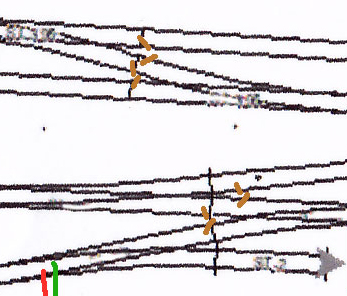
Hi Trevor … perhaps you missed my previous indication that I altered the points from point 'X' to further west on the up side platform approach … thus generating the extra length you mentioned. It would mean that a 08 shunter coming in from the left side of the track plan you see above would use the up side of the platform to run into the siding and yard even thought unorthodox … using the reverse to come out with freight as necessary. The alternative would be to do as you suggest and noticeably reduce the platform roads to give more length to the pair of tracks on the right.I have made some point alterations which may help a little at least - see below where the points have been shifted to a new position from the old one (marked with an 'x')

Actually I do not plan to have a fiddle yard at all. Thanks also for the initial schema you devised … all beginning to make sense now…
Paul
Posted
Full Member
Actually I did not miss it but presumed you would rather keep the original plan and keep to the integrity of the plan … in fact I felt a bit like an ashtray on a motorcycle suggesting you alter the plan entirely by re-orientating the yard not realising yours is based on an actual prototype!
I can work with your newer version but it may take a little while at this point!
Cheers
Trevor
Posted
Full Member
Posted
Full Member
A few extra switches here Paul… sorry about that mate … but it will cover your operating needs for quite some time. You could hold your railcar at the East end of the line as a "quasi fiddle yard" even though you physically can see it!
By using Centre Off switches, you can still apply the "one brain/one train" principle but have a degree of flexibility. The branch you are modelling had up to 3 freights a day according to Wikipedia so I wonder what the main traffic was? It seems a lot of traffic for a short line but what would I know?
Anyway, hope this gets you over the line … if you have any rationalising ideas for switches etc, let me know!
Cheers
Trevor
Posted
Full Member
As a potted history of the freight on the short 13-14 mile line, 7 of the stations had goods yards / sidings installed, initially for wheat, barley, hay & straw. This expanded to arable crops such as sugar beet, potatoes, cabbages, etc all of which came from the surrounding farmland and agriculture. With the market towns of Buntingford, Hertford & Ware in close proximity each having either maltings, plus along the line itself were a granary and flour mill, all local grain crops were in high demand. Livestock was also being shipped to market regularly at the aforementioned Buntingford and Hertford markets. Coal freight was also moved very regularly at the established coal merchants and specially extended yard in Buntingford, right up to the final line closure. As such, for a small line there was in fact quite some freight moved and depended upon from the Buntingford branch line from its initial opening and throughout its 106 year existence.
Now … onto my next thoughts … what track to use and what underlay, cork or foam? I'll research via this site for further real experiences of others.
cheers
Paul
Posted
Full Member

Posted
Full Member
Just a question… will the Danish Wood Oil enable you to paint your base with an Earth Tone paint? I am unfamiliar with the product you may be using!
Regards
Trevor
Posted
Full Member
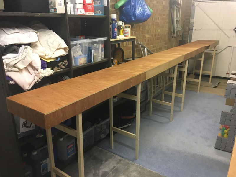
I'm not clear on what Earth Tone paint is so forgive me …. but I did a test for you using kiddies poster paint which is water based and standard matt emulsion for walls and ceilings, also water based. See below where I tried to apply one coat of each as evenly as possible.
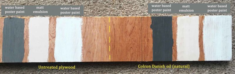
The results are clear … painting it is perfectly fine although I never bothered will oil based or acrylic paint as that would have no problems covering I'm sure. To the touch after a coat of Colron, the plywood feels exactly the same as it does not 'cover' the wood per se but penetrates the wood to make it more durable, give it some water of damp water resistance and brings out the natural grain and beauty of the wood. Why bother with that I hear you say …. and you'd be right … I only had some knocking about the garage and got a bee in my bonnet about taking an extra step to ensure the baseboard remained damp free and warp free, as it will be stored in said garage. Probably over kill to be honest but I only rubbed some in with a lint free cloth as a single application, not the standard 3 coats.
Hope that answers your question.
cheers
Paul
Posted
Full Member
The colours you have chosen seem to be a good range of earth tones so good luck!
Regards
Trevor
Posted
Full Member
I've scaled the whole layout design in Peco Code 55 track and tested my current loco / limited rolling stock on a section - they move freely and no bottoming out the sleeper on this lower fine-scale track - does anybody have any
thing dead against Code 55 before I make a more heavier investment as I couldn't find anything on the forum?
Also I'm leaning towards using cork track bed so are there voices with a stronger leaning to foam or anything else - have checked the forum and it seems various and all options of track bed have been used by forum members successfully so more a case of going with a gut feeling..
Cheers
Paul
Posted

Full Member
Coming along nicely.
Cheers
Marty
Posted
Full Member
Posted
Full Member
Thanks in advance, Paul

Posted
Full Member
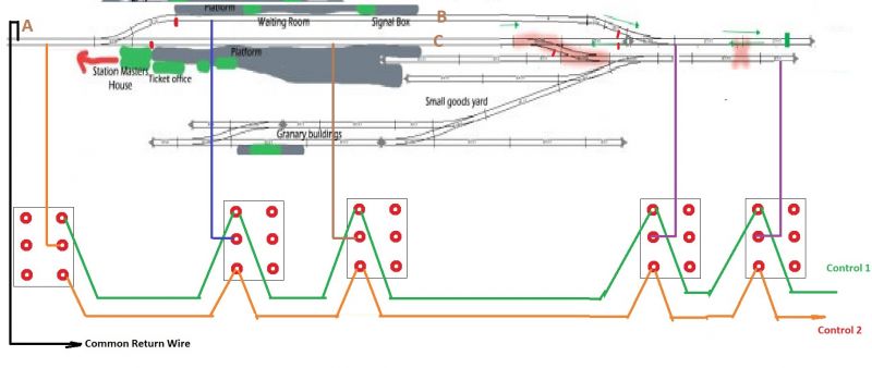
I have taken an earlier diagram and updated hence the impression of a cat going over it with claws and looking a bit messy
For the want of a couple of wires, you could increase your operating logarithmically allowing your two cabs to access the areas of your layout.
I have shown the common wire attached to the controllers. It does not have to be connected to a particular side as you will reverse the controllers in relation to each other in the act of operating your trains. However I suggest that you connect either of your controllers so that the direction switch is in the same direction that you want the train to head!
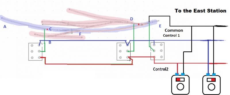
When you reverse controller 1, the train it is controlling will reverse as will the polarity of the rails. However assuming that the non common rail is positive, the negative return will go through the common wire and back to that controller to make a circuit.
Controller 2 will be independent in that non common rail is separated so if the polarity/direction is such that the common wire is carrying its positive path and the return will complete the circuit to controller 2 through the non common wire . No polarities will cross as long as the transformers for the controllers are separate unless you have a Gaugemaster unit
For your interest, when I get back up and running properly (I am in testing and renovation phase at the moment with 1 controller) I will have three controllers on a common rail setup and later will rebuild it to four controllers accessing all blocks on the layout using rotary switches as I initially suggested to you.
I have not dealt with your point motors but make sure the switches you use are MOMENTARY contact ones as you do not want to risk burning your point motors
Hope this helps, but feel free to ask for clarification…
Regards from OZ
Trevor
Last edit: by xdford
Posted
Full Member
I'm not 100% sure I fully follow you but taking your description and diagram a step further for the whole branch I'm building, I've taken it as follows … would this be correct?

Another point (no pun intended) was to be sure I had placed the IRJ in the right places 'in general' - see the brown markings on the image below?
And yes, I'll be using the 'centre off' switches you kindly recommended previous in this topic to avoid burning out the motors.
Thanks again for the great electrical advice.
Paul
Posted
Full Member
You seem to have the top diagram in a nutshell! Well done!
Not sure about the centre off switches for the point motors but I will get back to you. Can you get a momentary contact switch that does not hold the power on to the point motor? Otherwise I have a cheaper idea
I will double check the insulated rail joiners for you as I go… are you using insulfrogs or electro variety?
Now to assist your drawing ability… get some sleep!!!
Cheers
Trevor
1 guest and 0 members have just viewed this.