Braughing to Standon branch design for N gauge
Posted
#230545
(In Topic #12614)
Full Member
I decided to start a new topic on my proposed layout design for a part of the old Buntingford branch line in Hertfordshire - focus on the section between Braughing & Standon. I already started a discussion with Trevor on the possible layout electrics and controller options but did not want to hog Bob's topic thread on his 'new small layout' where my own discussion came up. I have quoted in the 2 main items of the discussion below so they are captured.
Padster wrote:
Hi Trevor … apologies for the delay but have been travelling on business. Short answer is no, not replicating Bob's layout and going for a DC End to End layout single branch line, station and goods yards at either end - 18inch wide & 4ft long sections x 4. The red arrows indicate the direction the branch line will contact with countryside scene for around 6ft. Hopefully the attached layout design gives the idea of each end section. My enquiries were just to get my head around the electrical isolation to allow the main branch to trundle up and down with some goods yard and siding activity as well, as I intend this to be a 2 man operation either at home or at some small exhibitions … eventually :-)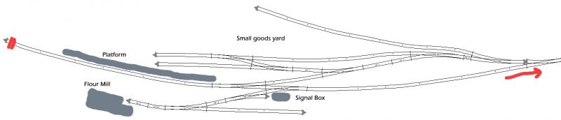

Posted
Full Member
This was a bit longer than my usual standards but hopefully it will become clear as we go along. Thanks Bob for your "imprimatur" so Paul here is an interpretation based on your input.
A couple of explanations.
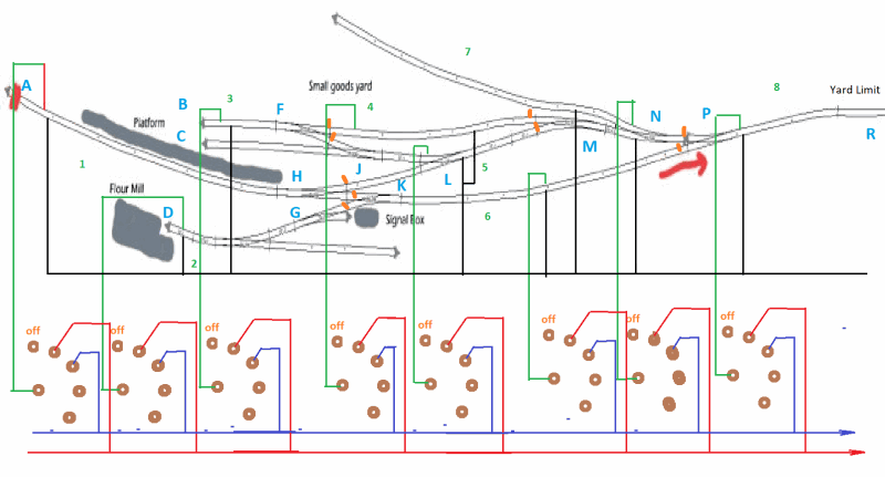
I have divided this section of your plan into 8 blocks (strangely enough numbered 1 to 8) and labelled discreet points on the layout A through to R using the draftsman's alphabet (No i o or q)
You said you wanted to be able to run a train on the main line while shunting in the small yard. Presuming that the operator at what will be the other end wants/needs/would like/all of the previous to be able to do the same at the other station. Hence I have used Rotary switches with 12 positions which I have shown 1 wire for each of 2 controllers ( or two sides of a gaugemaster) but you could use more wires to the other terminals up to 11 controllers. I used two for clarity purposes. Throttle 1 would be at 1 o clock on the switch, throttle 2 would be at 2 o clock on the switch and so forth. The orange strokes are the insulated joiners on the "North" side of the diagram.
I will be using a similar system for some parts of my own layout for block control when I expand to 4 controllers (after the move of course) but I do use the same system of aligning positions of the clock for setting the stalls on my turntable area using a single rotary switch.
The black wire is the common return for controllers and joins up to one side of every controller you want coupled while the rotary switch wires go to the individual controllers other side. The side does not strictly speaking matter!
I did make a couple of assumptions such as the point at G is a catch point? The Main line goes from A to H to P while an engine can shunt the yard coming out of the yard to a yard limit at point R? You may want to stable a loco in siding J to C or the track from N and upper or D to south of the Signal box (… sorry I forgot to put a label on those points) so the switch points can act as the isolator switch. Section B to F is individually blocked to allow a little more flexibility with shunting.
You may want more or less blocks but see if this suits you… and feel free to ask more questions if it is not clear
Cheers from Oz
Trevor
Posted
Full Member
Again, superb advice and help so far for this relative novice …. hope the move goes as smooth as poss Trevor.
Paul
Posted
Full Member
I was wondering if you were away again or not … I was updating Hints and Tips this morning (Wednesday) when I realised you had started a new thread. While it looks complicated the number of blocks to me is about right given a bit of operation scenarios but of course no two operators are going to see their layouts quite the same.
My own layout is (oddly enough) on my website at Resource not found as a 4 x 8 ft sheet. Effectively each of the three loops that a train can make is divided into three blocks which I find covers most but not all of the flexibility I would ultimately have liked but no doubt others would require more blocks and some less…
Try and work out your scenarios and we can adapt switching and gaps to suit! And maybe this will help a few others as well!
Cheers
Trevor
Posted
Full Member
strength and stop any twisting. 4 ft long by 16in width, two more to complete this coming weekend.

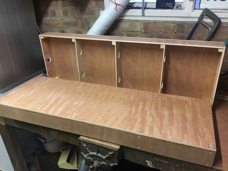
Was think of using these fasteners and dowel kits below (£7 or cheaper) for connecting the modules in the garage or at smaller exhibitions … anyone have experience of these or recommend anything better?
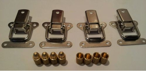
Also got some left over Colron Danish Oil to treat the plywood making it water and damp resistant which I think will be a good idea as it will be storage in the garage over winter times … although it is dry.
Next stop … selecting track (thinking Peco 55 or maybe 80) templates and marking up the modules for laying.
Paul
Posted
Inactive Member

I prefer these due to their adjustability, adjustable toggle catches,
https://www.amazon.co.uk/Rhinocoeu-Metal-Toggle-Adjustable-Cabinet/dp/B072B9YHVS/ref=sr_1_27?ie=UTF8&qid=1509021935&sr=8-27&keywords=adjustable+toggle+catches
Now I've finally started a model railway…I've inherited another…
Posted
Full Member
What a brilliant idea!
Terry
Posted
Full Member
Posted
Full Member
Hi Trevor. As mentioned in my other post on the module building I did get busy again but did not forget your great advice and thoughts and thanks for the sharing the link which I checked with interest. I did as you suggested and tried to work out the probable scenarios which I have tried to describe in visual form with written descriptions too.Hello Paul,
I was wondering if you were away again or not … I was updating Hints and Tips this morning (Wednesday) when I realised you had started a new thread. While it looks complicated the number of blocks to me is about right given a bit of operation scenarios but of course no two operators are going to see their layouts quite the same.
My own layout is (oddly enough) on my website at http://xdford.freeasphost.net/stag06.html as a 4 x 8 ft sheet. Effectively each of the three loops that a train can make is divided into three blocks which I find covers most but not all of the flexibility I would ultimately have liked but no doubt others would require more blocks and some less…
Try and work out your scenarios and we can adapt switching and gaps to suit! And maybe this will help a few others as well!
Cheers
Trevor
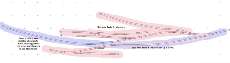
The maximum locos running at any given time will be 3 (assuming I have 2 colleagues available). 1 shunting in the red area, 1 shunting in the green area and the remaining one up and down the blue branch line. At times the red shunting will join the branch line to shunt to the south side, where the branch line train will be isolated in the 'Branch station area' top image or it will be up at the other end of the line in the station loop.It will also need to allow for the branch train to be isolated in the station area or the station loop to allow the shunter to move freight up and down the branch to either shunting yards.
I intend to use 1 power transformer for each colour area and I guess another for the points .. perhaps dual power transformers?? Also thinking of 3 Gaugemaster walkabout controllers.
If I'm running things alone at home or even at an event then of course only one train will be in operation at any given time as I move the branch train along to the other station, do some red area shunting operation and then bring the branch train back up … and perform more green area shunting operation there .. or variations of.
Probably sounds a little simplistic compared to many other layouts but I want a slow sleepy, branch line that really existing locally to me looking aged about 2 years before its closure … well thats the plan.
To me it feels like the number of blocks you described could still be valid but for the more simplified operation I described possible the block count, gaps and switching could also be simplified but I will bow to you greater experience of such things.
Thanks for any input and advice you can offer … I'm sure it wont be the last time :-)
Paul.
Posted
Full Member
You could get by with one switch with two selection areas to allow a train to run seamlessly from one station and have a "one engine in steam policy" so that only one engine is actually moving on the module at a time. This may not be a bad idea as you have relatively limited yard space and a shunter would have to block the main line to do anything in the upper yard. There is a lot to be said for a one brain/one train mode of operation. Alternatively the blocks could be handled with 4 blocks to enable totally independent shunting
The only issue would be relying on points for conductivity, which from my experience is not the best idea. My fiddle yard/ Reginald Bridge area is powered from the mainline block for the present using points as isolators!
Are you planning on your passenger trains to be loco hauled or auto-train style? If you want such a passenger train, it will need to "sit"at the station for a while so an isolator switch allowing a loco heading "west bound" to be turned off or "stabled" so a shunter can take the coaches away or the "return engine" can couple up and release the inbound engine when its train departs east bound.
Let us know… appropriate diagram will be forthcoming!
Cheers
Trevor
 Last edit: by xdford
Posted

Full Member
Although I do have the ability to switch my layout into a round roundly via a cross over my philosophy is similar to yours in that it is a single line branch with shunting opportunities at stations, yards and lineside industries.
I’m running mine on two controllers, with multiple blocks and isolation sections. There will be opportunities for 3 operators, two drivers and one Signalman. Getting 3 people into my layout room however is another matter! They had better be friendly.
Good ideas here and with Trevor’s expert help you’ll get a robust plan in no time.
Keep it coming.
Marty
Last edit: by Marty
Posted
Full Member
Hi Trevor,Are you planning on your passenger trains to be loco hauled or auto-train style? If you want such a passenger train, it will need to "sit"at the station for a while so an isolator switch allowing a loco heading "west bound" to be turned off or "stabled" so a shunter can take the coaches away or the "return engine" can couple up and release the inbound engine when its train departs east bound.
Let us know… appropriate diagram will be forthcoming!
Cheers
Trevor
Brilliant advice and thoughts, you guys really rock helping as you do and this site is amazing for the novice to see, learn and gain experience ,…. whilst having fun and enjoyment which is what its all about.
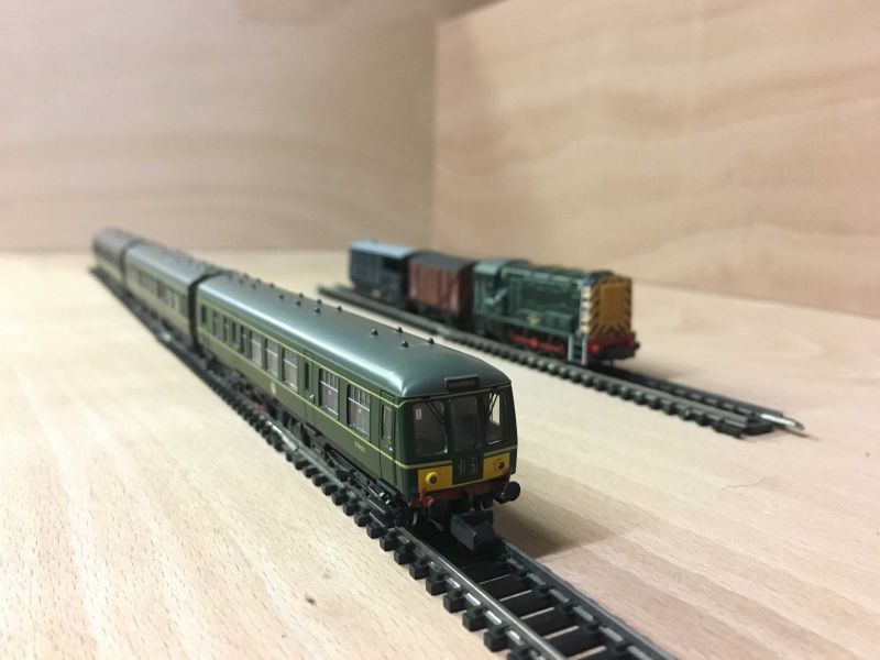
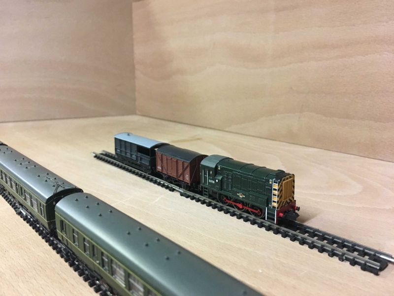
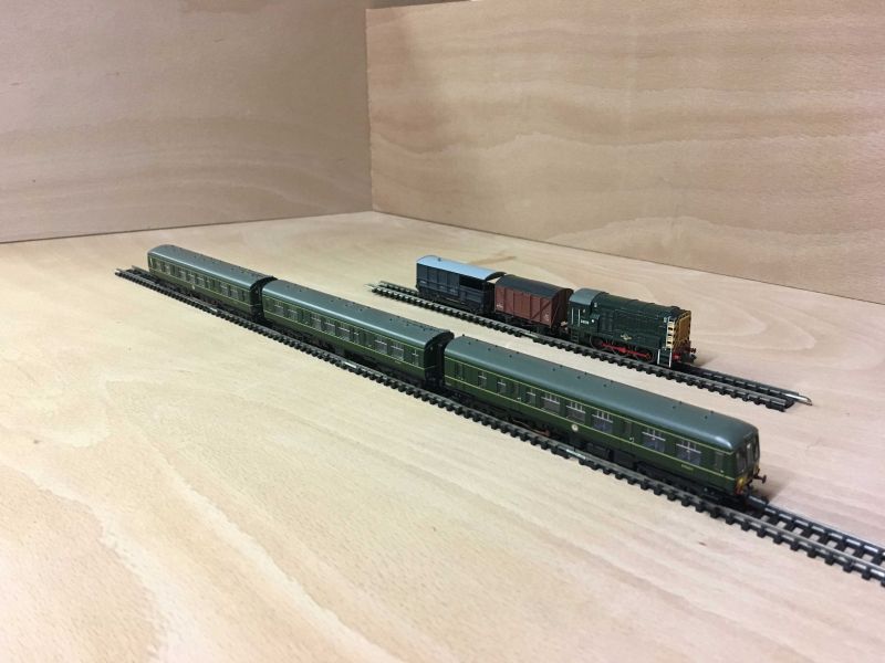
As for your question, let me expand a little which I should have done previously. The branch passenger train will be a DMU which was used for the last 5 years on the real line before the Beeching closure - originals were 125 Class Derby 3 coach but these are not avail yet in n gauge so I settle for 108 Class which is very close.
The yard / siding movements will be Class 80 diesel shunters x 2. As such the shunters will only move around freight. Hope that helps a little more .. photos below of the current rolling stock.
Posted
Full Member
cheers
Paul
Posted
Full Member
Hello Paul,
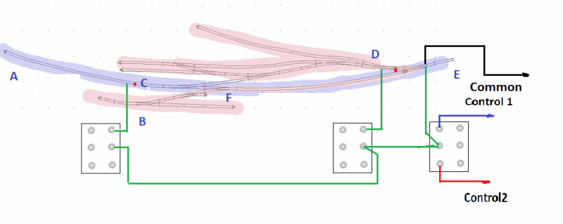
This is a much simplified switching diagram but given the size available, it should work OK.
The block switch to the right is to give you seamless passage between two controllers and the upcoming future module to the East or Right of the present module for your railcar and I assume you will run goods trains between the two stations.
The other two switches will be just used as on/off modes. By having the insulator at point C, you can isolate your rail motor between A and C but you can also run a loco hauled passenger train in and bring a shunter or returning engine in to remove the consist and/or return the other way.
You can be busy shunting the whole yard until the rail motor is "due" and then isolate the shunter in the yard at "D" until the arrival and the head shunt on the main is clear, when the railmotor is isolated and the shunting can continue. If the Shunter is between B and F, the points at F will isolate the shunter anyway until the line is clear.
I am not that familiar with Bachmann N scale trains but I presume that the rail motor has 1 powered car and 2 "trailers" similar to the older Triang sets in OO? That would mean that the powered car could face "West" and the insulated section "A-C" could be a bit shorter.
Hopefully that will ease any wiring concerns you may have had and a few others can learn from it as well!
Without trying to tell you how to build your railway, I am thinking that you should consider changing the orientation of your yard in the future module so that it is reversed and coming off the main at the left of the the entrance … have a think about it if it enhances your idea of operations
Regards from Oz
Trevor
Last edit: by xdford
Posted
Full Member
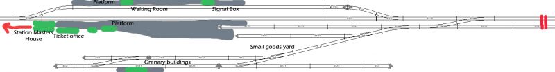
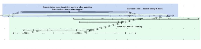
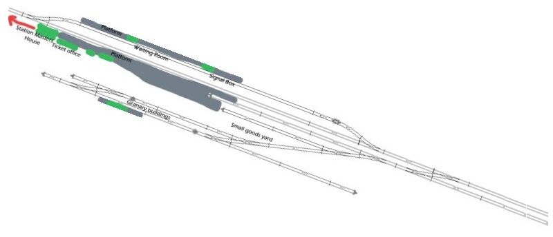
Here's how the whole section of the branch i'm building looks like to module format - 4ft lengths each one..

Based on your thought that maybe the east station and its yard could be altered to aid operation, you have a valid point - my only resistance is I want the model to depict with best accuracy how this stretch on the line looked in real life. That said, I have made some point alterations which may help a little at least - see below where the points have been shifted to a new position from the old one (marked with an 'x')

I'm assuming I can follow a very similar block and switching setup on this section that you depicted on the previous section … and would you have any photo images of the types of block switches I should be considering - I need to get this stuff visually in my head and then I'll be fine…. I think :-) !!
Thanks as before for the valuable hints and help.
Paul
Posted
Full Member
The switches I would suggest using are shown on http://yourmodelrailway.net/view_topic.php?id=9970&forum_id=21&page=1 on Ken's switchboard … we are going to the new house today so time is limited. There are other versions of the same thing which I will send you!
I have a couple of other ideas that would help you maintain your prototypes integrity with the yard which I will illustrate when we get back here tonight…
Cheers
Trevor
Posted
Full Member
Posted
Full Member
Would you know what product Ken used to create the station platform base - see photos about 6 replies down in his thread?
Paul
Posted

Inactive Member
I used plywood 10mm thick Paul (or 7mm plus 3mm of hardboard glued together will also suffice) and fixed it down with a couple of countersunk screws. Very stable with no warping of any kind.
Ken.
'It don't mean a thing if it ain't got that Swing'
Posted
Full Member
I cannot draw the full thing but if you change your track plan angles, you should be able to fit in a slightly better length head shunt track (… I know - it is the "up" track on a double track line… ) to wit (although it is exaggerated)…
so with a little shortening of the platform roads, the upper track of the pair of tracks in the bottom right hand corner would perhaps be long enough for an 08 and a few four wheelers off the branch which is I would think typical of the traffic…
Is there a plan for a "fiddle yard" to the right at all? That would indeed increase your operating possibilities logarithmically … then again we would all like more space!
Cheers
Trevor
1 guest and 0 members have just viewed this.