My new layout
Posted

Full Member
On30 - again
Hi All,A "one step forward, 2 steps backward" day. Working on the 3D print model this morning I noticed that the 2 styrene pieces that keep the donor Bachmann chassis in place seemed a bit loose. These had been glued in place with a CA formulated for "difficult plastics" with a surface keying agent to help things along. Worked fine on the styrene (the thin film of CA is still there), but not on the nylon of the 3D print. So a gentle pry on the other bits of styrene used in the bash gave exactly the same result. I now have a naked shell, and a pile of styrene bits.
Not often I throw the towel in, but this has gone beyond the pale. It's now in the trash bin sans cab, which I can use in something (I think, derelict rusting cab in the weeds?). I don't know whether anybody else has run into this problem, but it seems to me that modifications/additions to a nylon 3D print are going to be temporary at best if using CA (or any other adhesive for that matter, due to the slippery and inert nature of nylon), and will probably require screws or NBW to keep things in place. Makes me wonder how window plastic will attach. Probably not is the answer.
That now orphaned Bachmann Bo-Bo mechanism will have a styrene or more likely a brass body.
One of life's little "well I never" moments. An interesting experience that will definitely not be repeated.
Nigel


.
©Nigel C. Phillips

Posted
Full Member
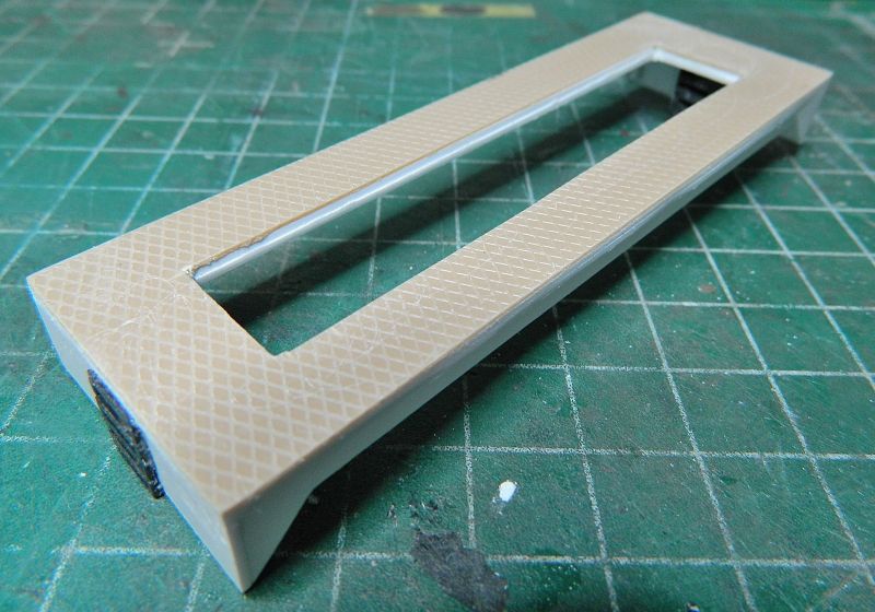
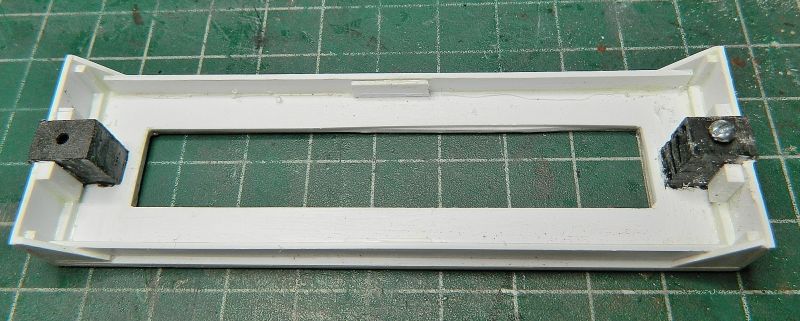
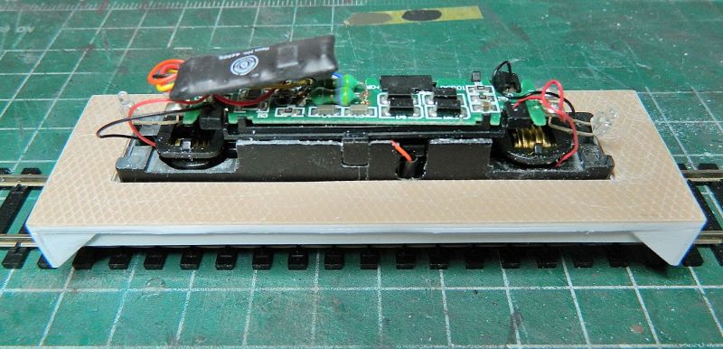
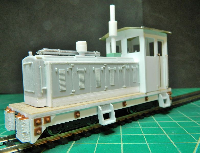
Time to move forward. I did a "boxy" end cab/center cab body shell design in CorelDraw last night, along with a footplate, to go on the Bachmann 40 tonner chassis, which was orphaned after the issues with the nylon 3D print body shell detailed previously. An hour to spare, so the following is the result using white styrene sheet and bar, and some O-scale diamond tread styrene sheet that I found in the roundtoit box. Tools were nothing more complicated than the large box cutter (Stanley knife), steel ruler and square, plus the Mk 1 eyeball. The footplate is a laminate of 3 layers, with the grain of the styrene sheet in different dimensions to minimize warping (cut one, turn sheet 90°, cut second, turn 90° again, cut third). I'll be adding a couple of "wood" buffer blocks to shunt the buffered wagons, along with a few NBWs. Multi-position Kadee coupler as previously described.
Nigel

©Nigel C. Phillips
Posted
Full Member
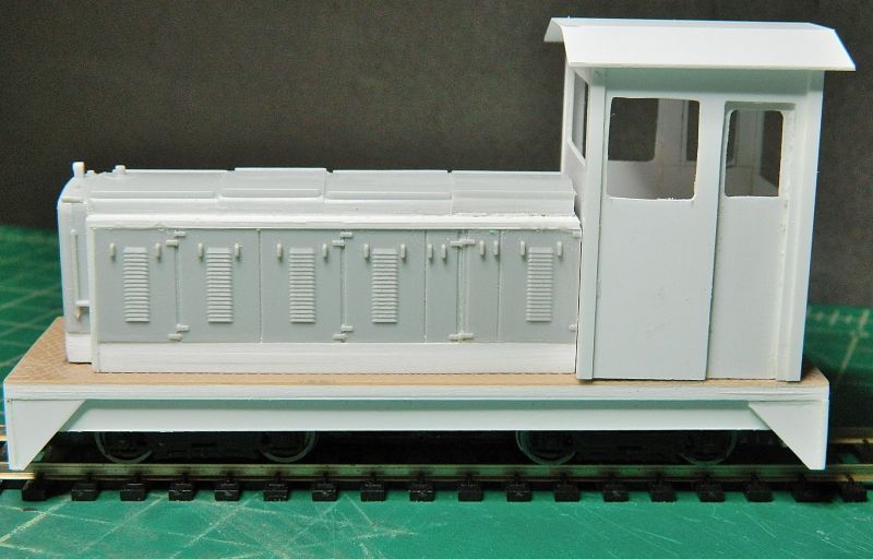
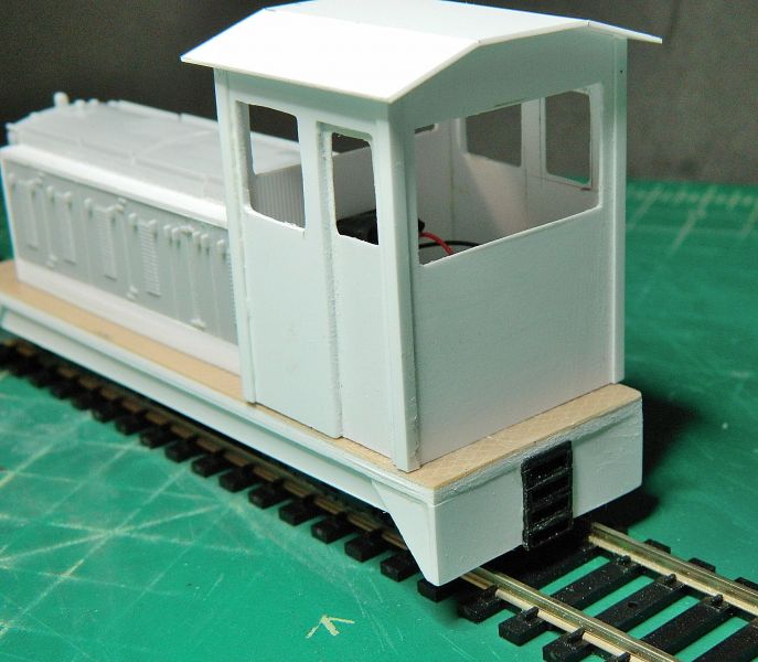
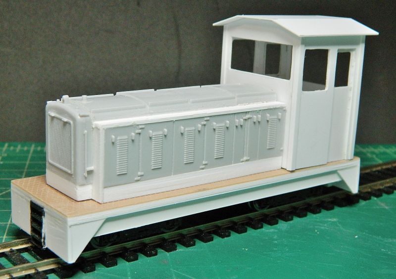
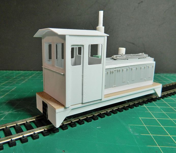
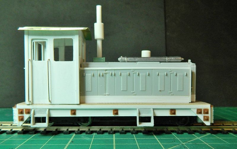
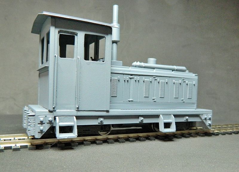
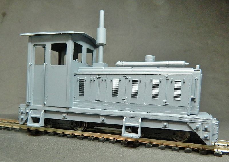
I found an hour last night to do some styrene cutting and gluing, plus some butchery on a couple of Dapol Kitmaster Drewry diesel kits (useful for odds and ends), the end result is shown below. Some center window panels and detail bits and pieces to do (wood buffer blocks, screen guard for the radiator, exhaust, air cleaner, hand rails, steps, rudimentary cab interior), the bare bones are there finally. About 75% less expensive than a 3D print shell, and a lot less work! Meets my 3-foot rule (as in looks OK from…). This is definitely not fine-scale modeling, but fine for my purposes, and it uses that orphan Bo-Bo chassis. I have another Bo-Bo chassis from an Atlas S2, so maybe another one will be in the works. Bit bigger of course.
Nigel

©Nigel C. Phillips
Posted
Full Member
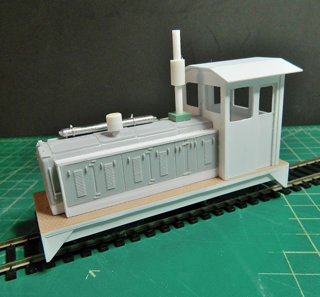
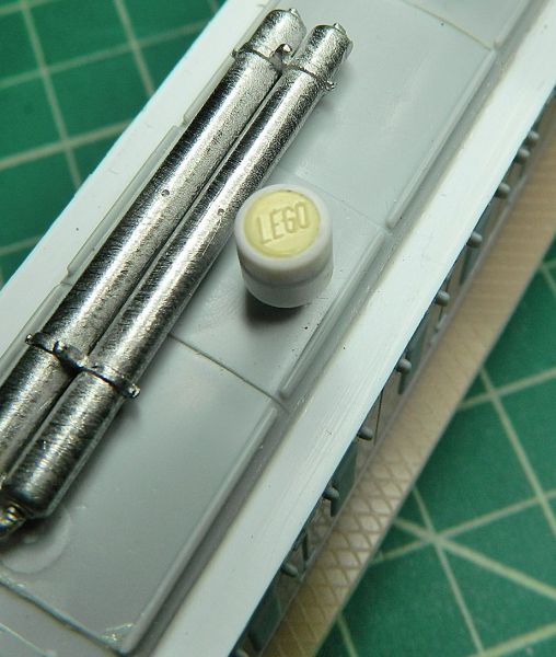
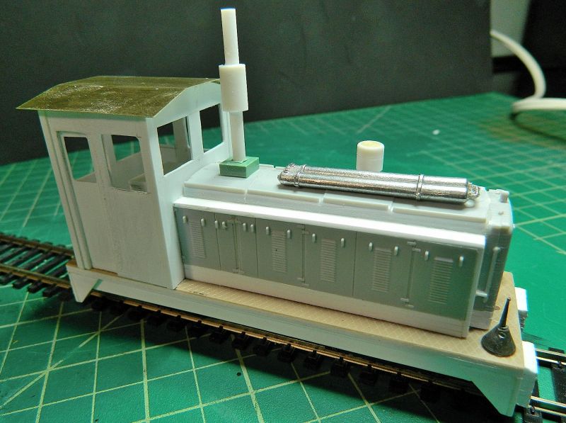
More progress on the Bachmann 40 tonner bash. Window dividers added front and rear in the cab, exhaust and muffler (silencer) fabricated, air cleaner fabricated, a start made on hiding the mechanism inside the cab, and I found a pair of "torpedo" air tanks in the spares box (scale 8" in diameter). Upside down until I decide exactly where they are going.These would have been normally mounted on the hood roof (and named after torpedo boats, where the torpedoes were stored on the deck). Use was made of Lego :small:bits and pieces here and there. Useful things, strong, lightweight, easy to work with and square.
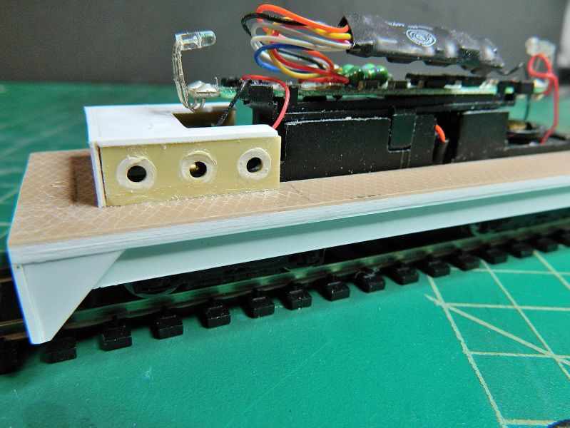
The eagle eyed will note 2 small holes, one in front of the radiator, one behind the cab, in the footplate. These are for the pin part of the pin and link couplers.
I'm slowly \getting there. With 2 RTR steamers ready to roll and 2 diesel locomotives reaching completion, I'd better start thinking about rolling stock and the layout design. And a couple of acres of corrugated iron siding for the buildings.
Nigel
©Nigel C. Phillips
Posted
Full Member
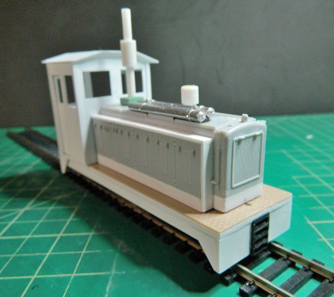
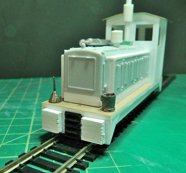
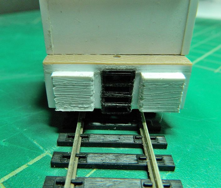
Quick half hour this evening, busy weekend coming up so no chance of modeling. Dumb buffers prepared and attached (suitably distressed, pain to cut, 3.2m thick, scale 6"), air tanks added (CA for plastics and metal) and a new tin roof (brass actually, scribed and bent to shape, easier to solder rain strips and the roof vent rather than use styrene). Plus a bucket to kick around.
Almost there, details, details…
Nigel
©Nigel C. Phillips
Posted

Site staff
https://notaglue.com
I used something similar to glue up a crack in a flimsy clear plastic hair dryer hood for Mother dear after she cracked it. Tried other glues etc but they all just cracked as it flexed but used one of these UV pens with glue and it welded it up great and so far its lasted over a year even with Mothers 'gentle' handling :roll: Just wondering if anyone else has given it a try ? Ok not cheap but might do the job
Cheers
Matt
Wasnie me, a big boy did it and ran away
"Why did you volunteer ? I didn't Sir, the other three stepped backwards"
"Why did you volunteer ? I didn't Sir, the other three stepped backwards"
Posted
Full Member
New one for me, sounds interesting. UV activated plastic filler. I shall order some and test. Thanks for the info.
Nigel
©Nigel C. Phillips
Posted
Full Member
I asked Bondic whether it would work with either Nylon 6 or 12. They don't know (not sure that they knew what it was, but you never know until you ask). 10/10 for a prompt response though. Reading the blurb more fully this really looks like very similar to UV activated dental filler, and it has to accessible to the light. I hesitated to ask whether it was short or long UV…
Given I've moved on from 3D print bodyshells (once bitten,,,) I'll save the money ($15 a shot + $9 refills).
Nigel
©Nigel C. Phillips
Posted
Full Member
Detailing afternoon. Cab roof (in brass, bent to shape after a bit of judicious scribing on the inside, rain gutters and hatch from bits of scrap brass and N/S), hand rails (0.02" P/B wire, I used Bill Bedford's hand rail bending jig), steps and instrument panel (ex Dapol Drewry), some NBWs here and there. Not quite done, I'll fabricate the radiator guard when I get some large mesh. Which is getting like hen's teeth to find. Musn't forget the horns, the lights and windshield wipers. Door handles. And the crew. eebygum here we come.
Nigel

©Nigel C. Phillips
Posted
Full Member
Nice afternoon, the sun was shining, so I gave the body shell and roof 2 coats of primer. I'll give it a coat of clear acrylic in a few days, and then do some fine rivets and seams, followed by another coat of acrylic and the the final coat. The various detail bits and pieces are proving difficult to source. Either way too expensive or too big, being scaled for full size O scale. I shall have to look at S-scale (1:64), HO, or Shapeways (Oh no!). Or make my own. I like that idea best, no real cost except my time, and everyday is Saturday. My electric screwdriver makes a decent low RPM lathe, so a couple of horns from styrene rod should be easy (famous last words).
Anyway, the almost end result is shown. Looking at it I think I may up the shell a mm or so to give a tad more exposure to the bogies/trucks and the fuel tank (for which I need a filler pipe).
Meets my 6-foot rule. Bit rough around the edges, but it'll get weathered after the rivets and seams, plus a few more details such as tool boxes and chains on the footplate will hide the joins.To give some sense of scale, it's 125 mm long by 65mm high at the cab roof (around 5" x 2.5"). I costed out the time and money spent on this compared to the 3D body shell print. Time: Half of what I spent on the 3D shell. Cost: Around $3.60 compared to nearly $35 with postage. Most of the materials came from the styrene and brass off-cut box. Plus 4 bits of Lego, that's where the big bucks went. The other expense was in blades for the knife and glue, and the bit of solder for the roof. Cheap modeling, and I'm happy with the end result. It's based on a variety of prototypes, so pretty much a generic model.
I'll be starting another thread on the actual layout, this one I'll keep for kit bashing and scratch building.
Nigel

©Nigel C. Phillips
Posted

Site staff
must be a wide baseboard then

Ron
NCE DCC ; 00 scale UK outline.
NCE DCC ; 00 scale UK outline.
Posted
Full Member
Thanks. The 6 foot is the other end of the layout. I just take my glasses off when it's in front of me. And dim the lights. Looks even better.
Nigel
©Nigel C. Phillips
Posted
Full Member
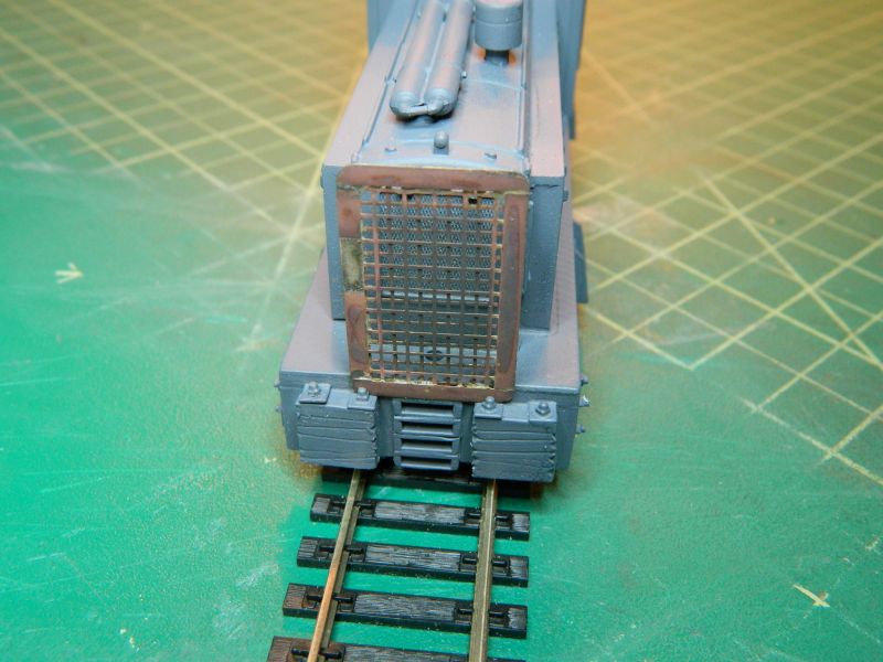
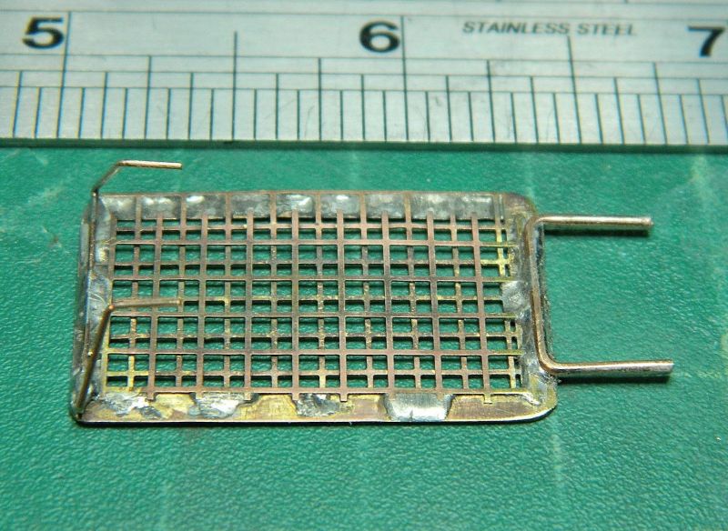
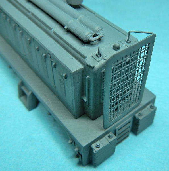
K&S brass mesh is turning out to be very elusive, so I used 2 layers of large square mesh (around 3.5mm) and some thin brass sheet for the frame. The idea of a mesh screen in front of the radiator screen is to prevent damage from large branches, track debris, bricks, beer bottles, etc. End result shown below. Good 'nuff. Vallejo matt paints I think rather then rattle cans. These screens would have been fabricated on site from whatever was around - old steel bar and rusty fencing mesh usually. Why break with protocol practice? Needs a few dents though. I dipped it in my blackening solution - rusty brown was the result (not bad, but I'd better get some fresh as I recon it's cream crackered). I'll scrub that off with kitchen cleanser cream before painting. I have 2 stays to fabricate to keep it in the upright position (P/B wire bent to shape in a V). Those pips on top of the radiator cowl look to be the right place, Note the fine-scale weld seams on the frame and crud collecting at the bottom ( :hmm).
Off to the local craft store in a bit to see if they have some angels with trumpets in the Christmas stuff (horns with postage are coming to round $5 each) and something that I can bash into lights.
Nigel

©Nigel C. Phillips
Posted

Inactive Member
It's looking good. :thumbs
I found that wall board screws make good trumpets, as they have smooth, flared heads.
I filled the cross slots (Phillips), and ground the threads off.
Just a thought.
Max
Port Elderley
Port Elderley
Posted
Full Member
Thanks. I think I know the ones you mean, coarse thread, hard plastic, hollow core, used for screwing into sheet rock. I shall investigate. If I put a screw partially in I should be able to cut the head off and put it in the drill for filing..
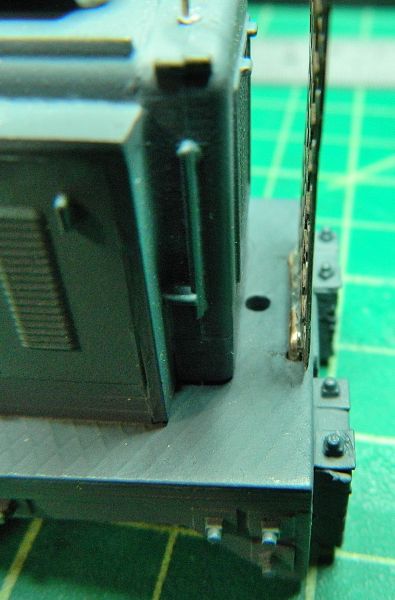
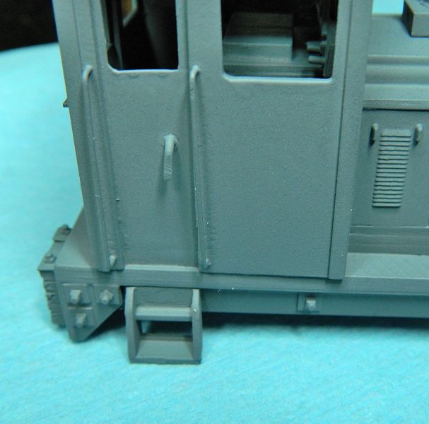
More progress, supports soldered to the frame, holes drilled in the body. it's a friction fit at the bottom,, the top stays are decoration only. The photo shows the back, tack soldered in place. Plenty of space to drop the coupling pin in behind the screen using a pair of tweezers. A couple of drilled through NBWs will go on top of the radiator shroud for the stays to go in.
For those interested a photo of the fine-tip soldering pencil. Feedback temperature regulation, ideal for fine work. $12 from Amazon, and it's been going for over a year know.
Nigel


©Nigel C. Phillips
Posted
Inactive Member
I'll see if I have any left, and take a photo.
Cheers
Max
Port Elderley
Port Elderley
Posted
Inactive Member
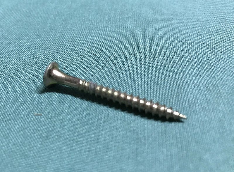
I don't know what they are called, but I've put the thread in the drill and then used a file to shape the shaft.
Then cut to length.
Sorry about the depth of field. I used my iPhone. :oops:
Max
Port Elderley
Port Elderley
Posted
Full Member
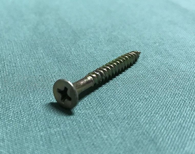
Steel flat head Philips wood screw with plain shank. I see what you mean. Neat. Usually have a few boxes around. Looks like a #6 or #8 will work. A Robertson head might be easier to drill out to a hole.
Nigel
©Nigel C. Phillips
Posted
Inactive Member
I tried to drill out the cross slot, but the steel is so hard that it broke the cutting edges of my drill.
I ended up filling it and painting it black.
Max
Port Elderley
Port Elderley
Posted
Full Member
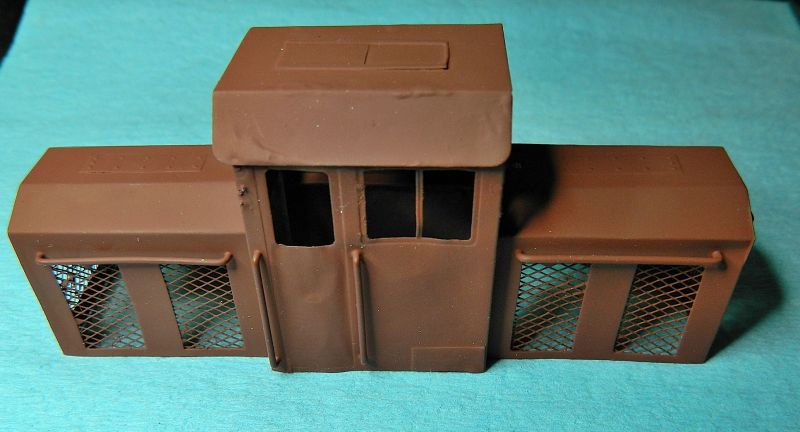
Nice afternoon again, so a bit of painting and decoration after the detailing yesterday (handles for the doors of the grey one along with some drilled-out NBWs on the radiator shroud for the grill stanchions). I'll do door handles for the now rust brown one over the weekend. The red oxide primer is close enough to rust so that it can be revealed after gently sanding down the final top color. Two coats of oxide primer just in case. Engine exhausts for the brown one were prepped from decreasing diameter styrene tubes, I'm waiting for the glue to finish outgassing before tapping for screws. It will need a few days even although the glued up section is only an inch or so. Otherwise the plastic will be too soft (although self tappers would be fine). I'll attach after painting.
I shall experiment with Max's approach with smooth shank steel screws once we're over Thanksgiving. Definitely cheaper than plastic or brass O scale horns (which are a bit too big anyway). It also looks like I'll be making the windscreen wipers from scratch as well. That could be interesting.
These 2 locomotives are almost done, nothing much left but the final detailing and painting. I'm a lot happier with the scratch built one, as well as the brass kit one, compared to the 3D shell, so I will continue along the same pathway for future locomotives. I like the cost as well. I've deliberately refrained from using off-the-shelf parts except the chassis, might as well continue to be cheap and cheerful. Fits in with the layout coming up - one step removed from derelict but still running. I've a couple of candidate chassis' for some O scale bashes over the winter, should keep me busy.
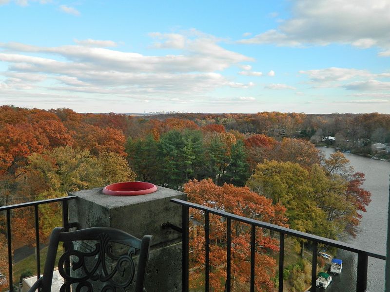
Last photo is the view from the spray booth (placed on it's usual position on top of the balcony table). The leaves are past their best, but still a great view.
Nigel
©Nigel C. Phillips
1 guest and 0 members have just viewed this.