My new layout
Posted

Full Member
On30 - again
Hi Bill,Thanks. No reason to change the motor, it works fine even although it's an older design. Even under DC. Just goes better under DCC when crawling along at walking pace (plus sound, lights and the ability to have 2 or more locomotives on the same track). Being made in 2000 makes it among the younger of my locomotive stable, the oldest is probably late 1960's-early 1970's. I draw the line at old open frame motors with a 4-5 amp draw current though. Those get replaced with a modern DCC can motor.
On30 does have the advantage of a bit more space to do some detailing.
Nigel
©Nigel C. Phillips

Posted
Full Member
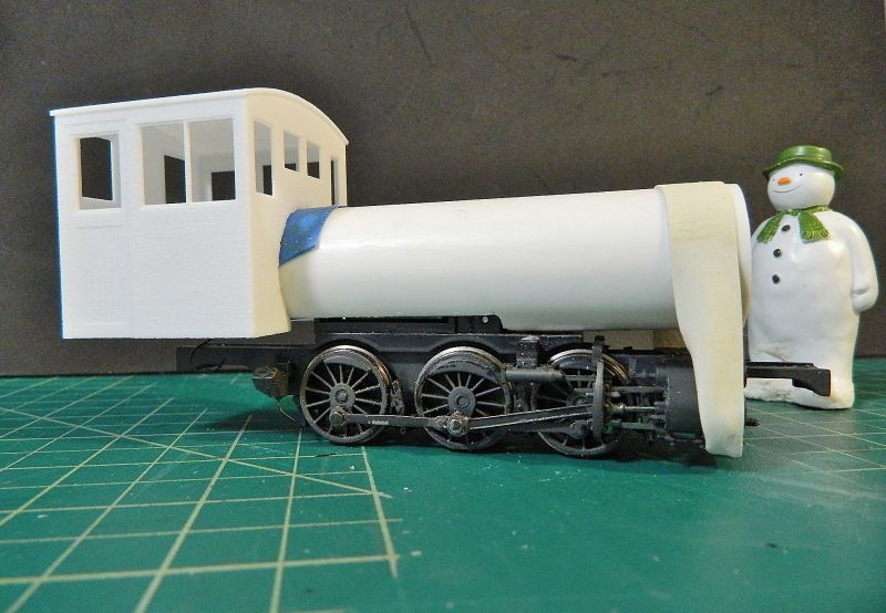
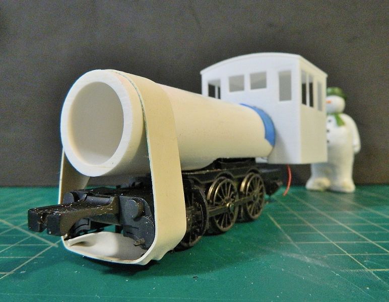
I got permission to show the picture below. This is a 0-6-4T Forney, built by Porter in 1911, and in use up to 1951 by the Godchaux Sugar Company on their 3'6" narrow gauge system in Louisiana. I was going to use a 2-6-4T arrangement, but what's a pony here or there (or a foot in gauge!). Helps keep the dimensions smaller as well.
The usual assorted clutter on the boiler (sand domes, sand pipes, electricity cables, steam dome, lights steam turbine electricity generator, bell, injectors), and on the other side there would have been an air pump and air reservoir tank for the brakes.
I also found a dimensional diagram for a 0-4-4T Forney built by Baldwin, which will be useful for the boiler, cab and bunker build. Some Archbar trucks (bogies) came today, so no excuses. The boiler diameter was 46", 1:48 scale means a diameter of 0.96". I found some brass pipe joiners in the plumbing section of the local DIY store this morning of almost the same diameter. The driving wheel diameter was 42", 1:48 scale means 0.875", the Bachmann drivers are 0.8", close enough for me. The pistons will require some work. More on that topic shortly.
Blodgit and Fudgit need to get cracking, as they clearly will be stretched to the limits of their incompetence with this one. Less of the procrastination, more of the fabrication.
Nigel
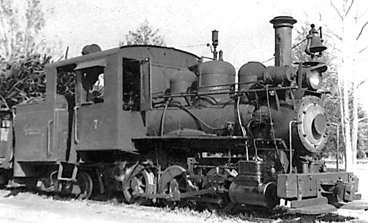
The photograph above is of Godchaux Sugar Company's 0-6-4T #7 Forney, and is reproduced from HawkinsRails.net with the kind permission of Ralph Hawkins, Webmaster.
©Nigel C. Phillips
Posted
Full Member
The question of pistons, gauge and scale (my perennial bugbear) arose early in the build this evening. Which is making me really think about the suitability of a UK donor chassis for the Forney bash. So…
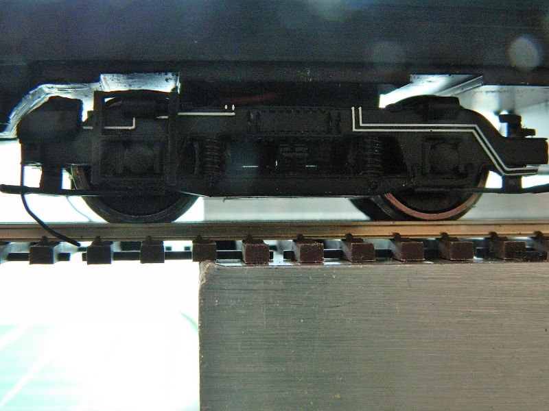
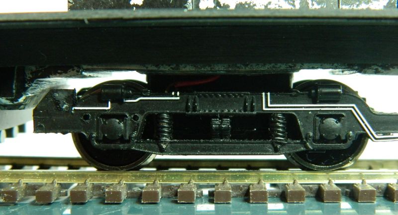
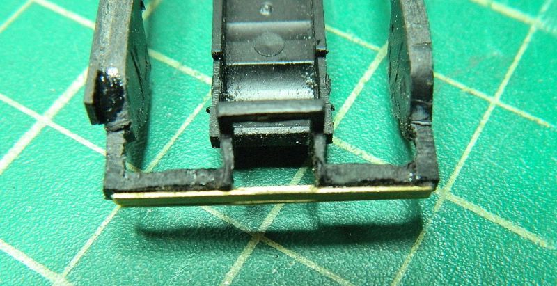
OO trains have a 4mm scale body but run on HO track (16.5mm, nominal 14.5mm back-to-back, although most manufacturers err on the side of caution and use 14-14.3mm). This is an issue if the body dimensions are adhered to. In the case of the 45xx the width over the cylinders was 8' 9.25" (35.08mm in 4mm scale). The width on this model is a scale 9.015' (36.06mm). Why slightly wider than it should be? There is a very practical reason for this - read on. This however means that the cross head guides and cross head/rods have to be angled in towards the wheels because of the narrow gauge wheelbase. In this case by 1.7mm either side. Have a look at the photo to see what I mean.
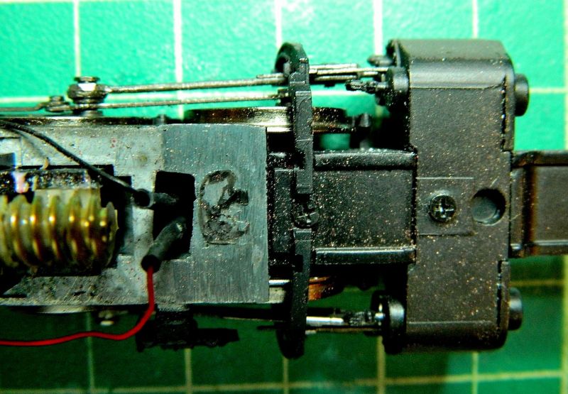
The amount of room available to bring the pistons in (which will mean removing a section of the saddle where the screw is) is for all intents and purposes zero due to the height of the pins holding the rod on the leading wheels (2.4mm, visible next to the motion bracket on the LHS of the photo below) , and the lateral play in the front wheels (1.15 mm). No wonder Bachmann had to make the cylinder width a bit more than the prototype.
There is enough meat on the center axle to widen the back-to-back by around 0.5mm, not nearly enough.This was definitely a "well I never, would you believe it?" moment. Now I could just bin those pisitons, and replace with some round ones with rectangular valve chests, but they would still stick out like sore thumbs. Same goes for longer pins and spacer washers on the central wheel.
The back-up plan for this chassis was a 6-coupled diesel mechanical with jack-shaft, so it looks like that will be the project for this chassis. I'll be looking for a Bachmann US 0-6-0 chassis, my NBHS should have some at fire-sale prices. If not it's eebygum.
Nigel
©Nigel C. Phillips
Posted
Full Member
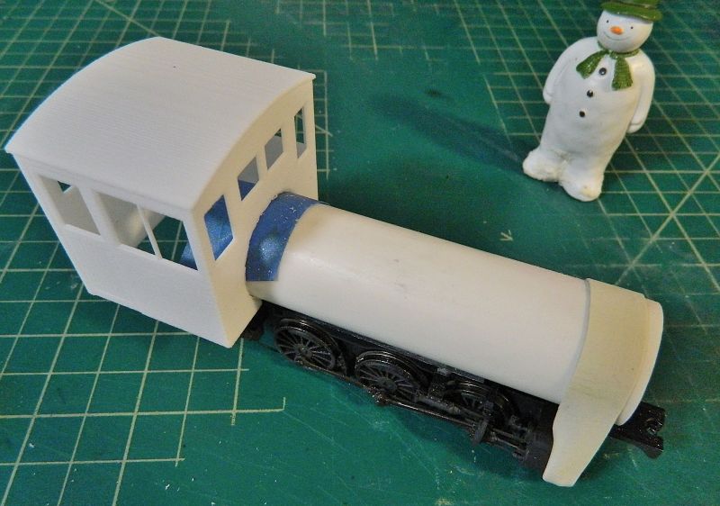
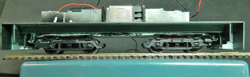
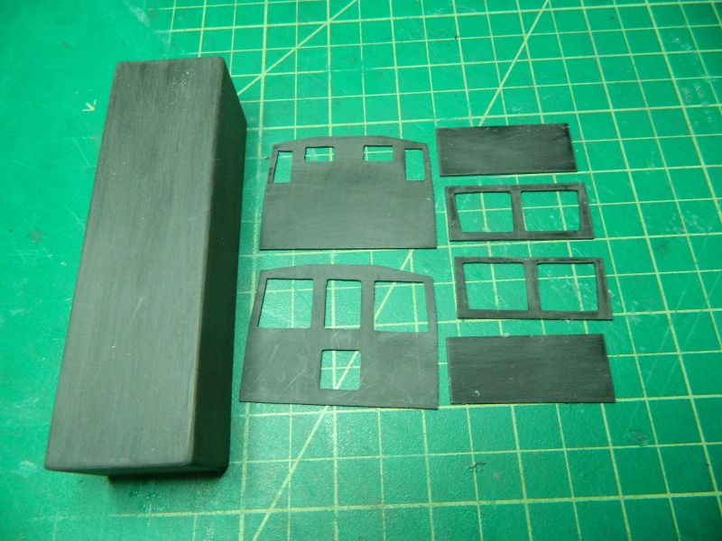
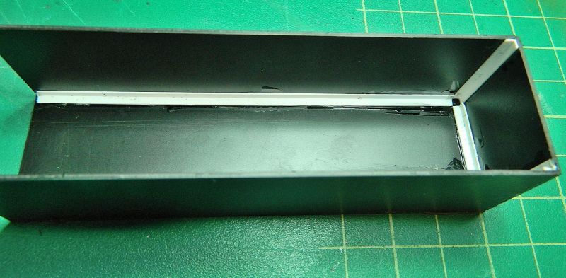
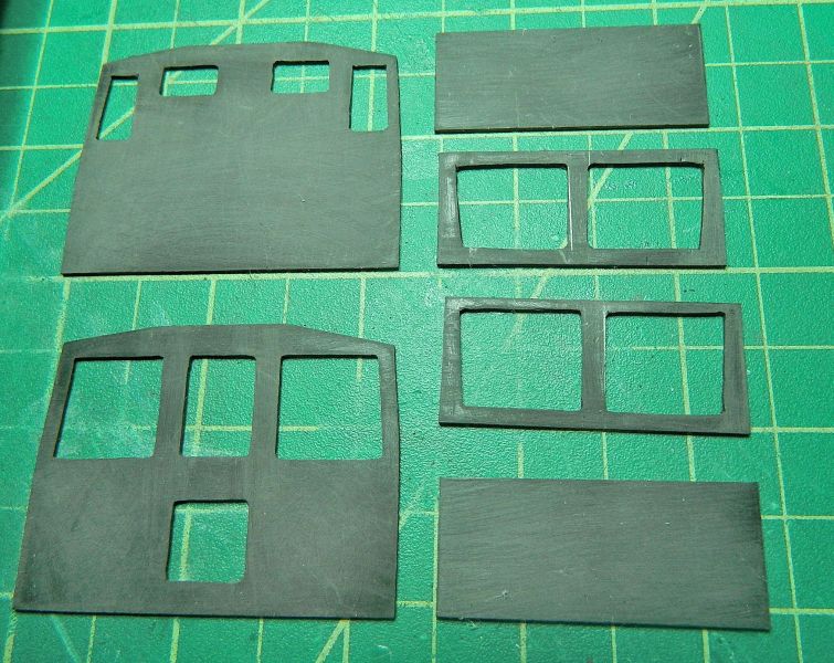
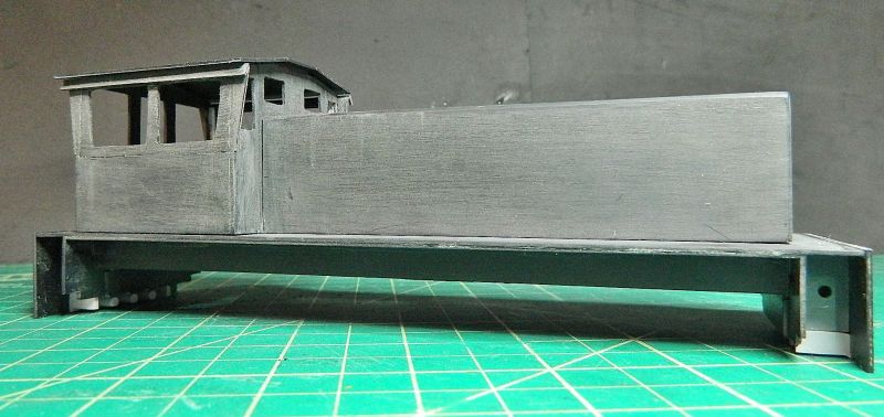
After a bit of a think I decided i could live with the geometry of the rods. I weighed the boiler in brass - ouch! Too much for that small motor. Onto Plan B - PVC tube. 1" diameter, 1/8" walls, internal diameter 3/4", so a tad over-scale compared to the prototype, but not much (0.958" versus 1", 46" versus 48" diameter ). This tubing is rigid, and rated for 480 psi - more than any regular steam engine. Cut to length, slot for the motor, and ready for the smoke box cladding, front, and back-head detailing (not that there was very much). I tried a test fit with a 3D print diesel cab, seems OK. See below. Interested passer-by got into the pictures. The black styrene sheet came today, so this week's project looks like the cab, bunker and frame extension.
Nigel
©Nigel C. Phillips
Posted
Full Member
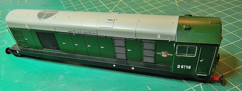
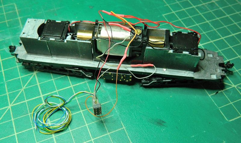
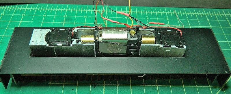
Something different while I wait for some items for the Forney build to come. In this class, a Bachmann class 20 diesel into a narrow gauge Bo-Bo heavyweight. The inspiration for this came from the Queensland Railway's diesel hydraulics that were converted to 2' gauge for the sugar cane industry in Australia. My intended layout needs at least one substantial diesel for hauling heavy loads, this fits the bill. I have an ESU sound decoder with the class 20, that will need re-blowing to a Hymec or similar. This actually a PITA, as the decoder will have to go to the UK to have this done. Last time I did this I was going to get dinged import duty and taxes on the value of the decoder (£120), not the re-blow (£15). Might actually easier just to get an ESU select and a generic diesel hydraulic.
First photo's show the body and and chassis of the class 20. I got rid of the Bachmann attempt at a DCC board several years ago, it was rewired with an 8-pin socket and wiring for lights. I only needed the body frame, as the body shell is not tall or wide enough. Five minutes with the fine saw solved that.
Next photo's show the footplate. This was made using 2 pieces of styrene, the first one plain, the other foot-plate tread.
I'll be starting the body this week using the black styrene sheet after some drawing in CorelDraw for the shapes.
Nigel
©Nigel C. Phillips
Posted
Full Member
One of those "hold on a minute, lad" moments. I assembled the foot plate using white styrene sheet and Humbrol cement (the stuff in the yellow bottle). Something was worrying me about this. This morning I consulted my modeling notes, there it was, Humbrol cement doesn't go that well with white styrene and Bachmann green plastic (as used for body shells). And so came another "well I never, would you believe it!" moment when it popped away from the Bachmann frame with a light touch of the cutting blade. Plus another one of those moments when I realized I'd made it too narrow (scale 7 feet instead of 9 feet).
So today we have footplate version II in black styrene, [Question: How do you see pencil lines on black styrene? You don't, use a white pencil or gel pen.]. I did the end beams while I was at it. Reinforced to handle the coupler pull. There is another pair of side beams to do, along with some steps front and rear. I'll let the cement harden before adding those. Tamiya heavy duty cement was used.
Nigel
©Nigel C. Phillips
Posted

Site staff
Ed
Posted
Full Member
Apart from not requiring undercoat when painting dark railway colors? Yes, it's formulated to be a lot more stable to UV light than the white styrene variety, and supposedly does not go brittle, shrink or deform after a year or so. Subjective observations, but it appears a tad softer, and is easier to cut/snap and bend. Glues up nicely, especially with the Tamiya cement. First try with the material, I'm very pleased so far. Downside is that it only comes in sheets, no rod, angle, I-beam, tubes.
Nigel
©Nigel C. Phillips
Posted
Site staff
All the sheets I have just happen to be black, but your quite right as all the angle, bar and tube I've got are white.
Anyway, back to your critters etc.
Ed
Posted
Full Member
Back to the critters it is.
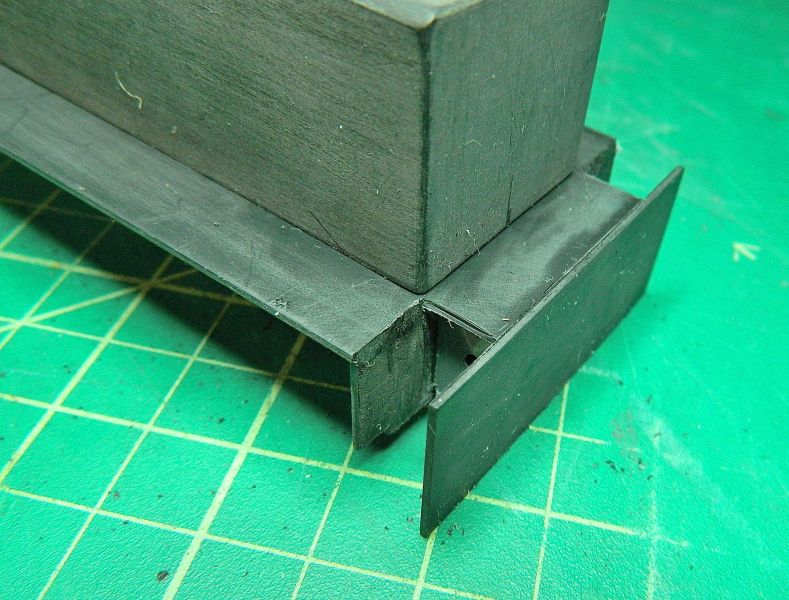
A second footplate was cut and glued down, some spacing strips added to the underside of the chassis to raise the height over the wheels ("sky" above the bogies/trucks is a prominent feature of the prototype, difficult with a gear tower model), and exterior buffer plates added. These were reinforced with some plastic engineering blocks I had handy to provide something for the coupler gear to pull against. This will be a surface mount with 2 levels.
The exterior plate and interior plate will provide the space for the access steps. I also levered off those Bachmann plastic covers on the "box" amidships, more on that later.
Some material needs removing from the underside of the MAZAC/ZAMAC chassis, that means taking the the bogie/trucks and gear towers out. The prototype has a Voith transmission and a transfer gearbox positioned in the middle, although most of that would be hidden by the fuel tanks. There are also cardan shafts to the inner driving wheels, and secondary shafts to the out wheels in the bogies. The brakes are already gone after the conversion to EM, the class 20 archbar needs beefing up a bit, and a representation of the cardan shaft made. The sand boxes need to disappear as well. Looks like a job for those stalwarts of the shop, Blodgit and Fudgit (motto: "by 'eck we can do it, and at no cost", overtime and ale excepted).
If I get permission I'll post a picture of the class. Lots of variation ( location of the fuel tanks, sand boxes, cab design, steps, lights…), so plenty of modeling license.
Nigel
Second footplate added and spacing blocks.
Buffer plate in position, the space is where the steps go. The small cut-out on the inner plate is for a flare in the steps at the bottom.
Reinforcing strips in place to elevate the footplate from the chassis.
"Sky" above the bogies/trucks. Needs more. A job for the big file
Bottom half in place on the chassis. It's long for a critter - almost 9.5". I had to compress a bit compared to the prototype dimensions, faithfully modeling that would mean scratch building a chassis (and running on On2 24" gauge track).
©Nigel C. Phillips
Posted
Full Member
Bit of hackery (with the hacksaw) and an attack with the big red file removed the blob uerneath as well as some metal above the wheels. Anymore and the chassis will start to get a bit fragile. Goodenuff, painted black and with some underbody details it'll do. I'll even it up with some styene strip.
Nigel

©Nigel C. Phillips
Posted
Full Member
I made a start on the modifications to the bogies/trucks today. The frames on the original are quite basic, the Bachmann ones are just not right. Bit of a compromise on the length and height, but it's the spirit I'm after, not a faithful reproduction. The cosmetic frames were cut from styrene sheet. Pictures tel the story.
The original Bachmann Class 20 bogie/truck, minus most of the brake gear.
The stripped down bogie/truck. The bottom part was removed, along with the strut that runs to the gear cover plate.
The replacement cosmetic frame glued in place with CA (consulted the notebook, CA works with styrene sheet, styrene adhesive does not).
Finally some brass reinforcing bar was added to the ends, which are in my experience the weak points of the design, This is the internal end.
And this is the external end that had the NEM 362 pocket on. Reinforcing bars are essential here as the cross bar is not connected..
One down, three to go. Then the brake levers and shoes. maybe some cosmetic coil springs as well. Plus those cosmetic cardan shafts.
Nigel
©Nigel C. Phillips
Posted

Full Member
Posted

Full Member
Yep, I'll second that emotion and I reckon your notebook must contain a mine of useful snippets Nigel.Hooly dooly … I love watching you do this strip down and rebuild from scratch process. I always learn something new too. Keep it coming.
Essential reading here for all modelers.
Bill
At 6'4'', Bill is a tall chap, then again, when horizontal he is rather long and people often used to trip over him! . . . and so a nickname was born :)
Posted
Full Member
Thanks. You are way too generous with your comments, this is pure bodge and fettle on the cheap. Compromise and compression, make-do or do without, and minimal expense.
On to today's episode. I finished cutting and attaching the rest of the cosmetic sides (as usual none of them are identical, but look OK from 6 feet - this is O scale remember). The brake shoes will need to be somewhere between HO and S-scale (1:64), choices with RTR are limited (read zero) for 1:64, HO are too small, so it looks like I'll be making my own, along with the springs and assorted hangers. One of the drawbacks of using a smaller-scale chassis.
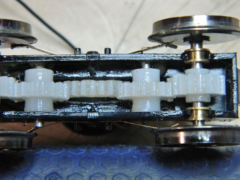
Looking at the innards of the bogies/trucks, I was struck by the state of the lubrication - starting to get a bit thick and discolored. Time for a clean-up and service. I removed as much of the old grease as possible (toothpicks and lint-free shop cloths work well), and while I was at it checked the gears for any splits/cracks/missing teeth. All good, so some fresh grease was applied, and the frames reunited with the gearboxes. Test fit to see what they looked like in the body shell. To my eye they certainly change the visual impression, even although they really are too small.
Bit of a break from the running gear coming up - the body shell. The prototype is a lot longer than the Bachmann chassis will accommodate, so some compression will be called for.
I now have 2 bogies/trucks with the beefed-up and simplified frames. Bigger axle covers would be useful, I have some adeas about how to address that.

End view showing the reinforcing brass bars on the coupler ends.
The state of the grease. Starting to discolor and get thick. The last lubrication was 5 years ago. Hmm.

Clean-up time. Also an opportunity to check the state of the pickups and the back of the wheels, as well as the bearings.
Fresh lubricant generously applied.
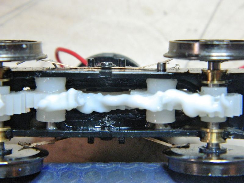
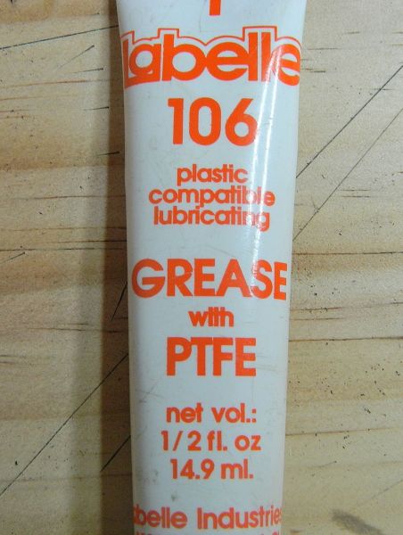
I use this for gear-sets and bearings, it's plastic compatible and doesn't cause swelling.
Quick check to see what they look like attached to the chassis.
Nigel
©Nigel C. Phillips
Posted
Full Member
A bit more progress today on the diesel body shell. The hood pieces were cut out and the hood put together with some white styrene angle inside, and the bits for the cab front, back and sides cut out. Final trim tomorrow, plus some scribe lines for the doors, and then the cab will be put together. Big windows are on the back, these locomotives run backwards, often double headed. Come to think of it, just like the class 20 still does.
I found a model of this on the web over the weekend in 3/4" to the foot scale (around 30" long, garden railway size, battery powered and radio controlled), I almost took up knitting until I realized the modeler had made just as many compromises as I have.in the build. Blodgit and Fudgit disappeared, probably drowning their sorrows.They'll turn up soon enough. That made me feel much better. My build uses a chassis that would be gathering dust, waste not…
I found some laser-cut louvers and doors online last week, they arrived in the mail today, peel and stick (the same company also does a peel and stick diesel center cab body for an On30 chassis, I couldn't resist, more of that later, that one will use an Atlas-Roco S2 diesel chassis that is also going spare).
More details on the Forney came at the end of the last week, specifically a scale diagram of the Godchaux #7 in the early 1950's, in addition to a photo I had not seen. The diagram and photo were in a magazine from 1995 (Narrow Gauge and Short Line Gazette), great read, not one company advertising in the magazine had a website, call or write. Plus 90% of them are no longer in business. I need a smaller diameter boiler, the perspex tube for that came today, limiting factor is the diameter of the Bachmann motor. The Bachmann chassis is not that far out regarding the wheel diameter and wheelbase, although I will need more air under the boiler. Busy, busy.
Nigel
©Nigel C. Phillips
Posted
Full Member
More bodywork construction today - cab assembled (after a false start, I put the window units in upside down last night :oops: :oops: :oops:, after the "well I never" moment this afternoon they came out with the assistance of a sharp blade, thankfully I didn't have to redo the windows), the cab was attached to the hood, and the wells for the steps at either end cut. I'll need a bit of filler for the joins on the sides following the upside down interlude. I went over the bodywork with some #800 wet and dry, hence it's grey color. Some filler in the gaps and then the steps are up next. Bit more final trimming on the windows, then it's onto the interior of the cab, the external detailing and a paint job.


Nigel
©Nigel C. Phillips
Posted
Full Member
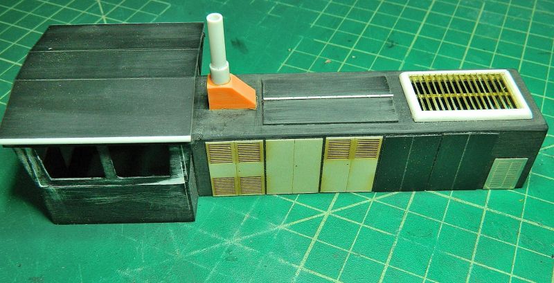
Some more progress on the B-B diesel.
1. Steps added (styrene sheet).
2. Side ventilated panels added ("peel and stick" from Mount Blue Models, laser cut ply, cut down 2mm in height to fit).
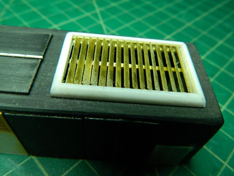
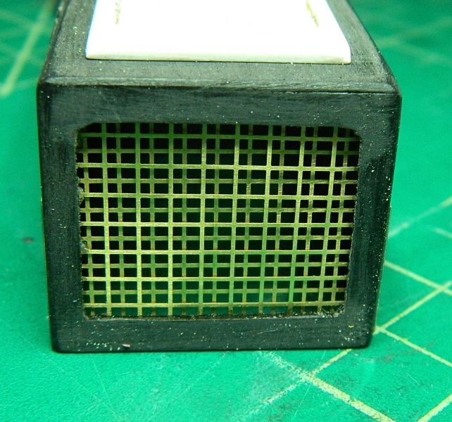
3. Front grill added (brass mesh, double layer).
4. Top ventilation grill (fabricated from brass strip and styrene) and bottom louvers (n/s etch, meant for a Sentinel) added.
5. Top and side access panels added (styrene sheet and rod "hinge" for the top).
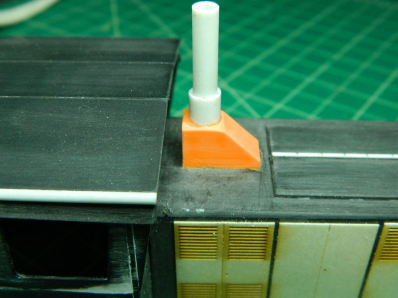
6. Chimney added (one of those nice plastic engineering blocks and some styrene tube).
7. Curved edges to roof added (styrene 1/4 round rod) and some interior reinforcing to keep shape (roof is just lodged on, it will be permanently fixed after a bit of cab detailing and windows).
8. Light coat of matt black (Krylon spray can paint and primer, goes on wood, plastic, metal).
Found some O scale horns of a suitable size at a show I went to over the weekend (Lionel, need drilling out). Sand hoppers next, then some railings, door knobs, levers), and a fuel tank and filler.Plus rewiring for DCC sound.
Nothing complicated on any of this, so I'll let the pictures tell the story. The hood is not sitting flat due to a trapped wire.


Nigel
©Nigel C. Phillips
Posted
Full Member
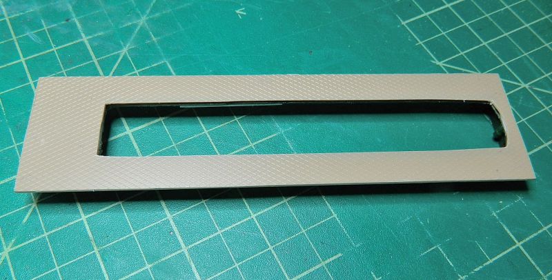
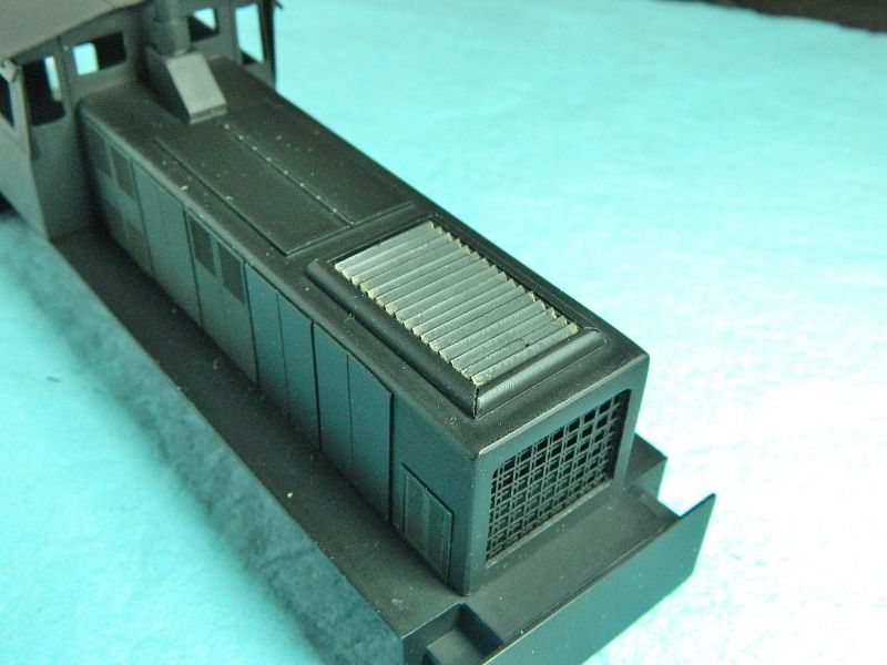
I found a Bachmann 2-6-0 (Mogul) On30 locomotive along with 3 On30 coaches (passenger cars) with lighting at a show this last weekend, going for a song. The seller admitted defeat in trying to convert the locomotive to DCC. Not a good sign. Missing one axle and wheels on one passenger car, a few loose and broken bits on the body shell, and just as money was about to change hands he mentioned that he had drilled some holes in the tender for the planned speaker and decoder. "Whoa there" sez moi, pulling my money back. So after a bit of haggling and "how about throwing in that box of O scale windows and doors?" down went the price even more. The set came in a big box along with some HO snap track and a DC powerpack and controller. This is still a current model (and still DC), so spare bits are not an issue (including the running chassis and the body shell). I recon it's a first run, so getting on for 20 years old. From the lack of wear on wheels very little running time, probably around the Christmas tree once a year.
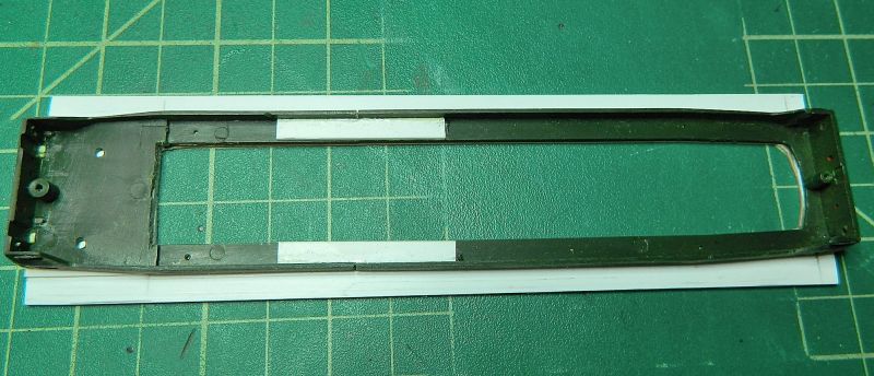
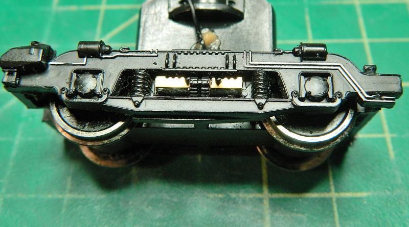
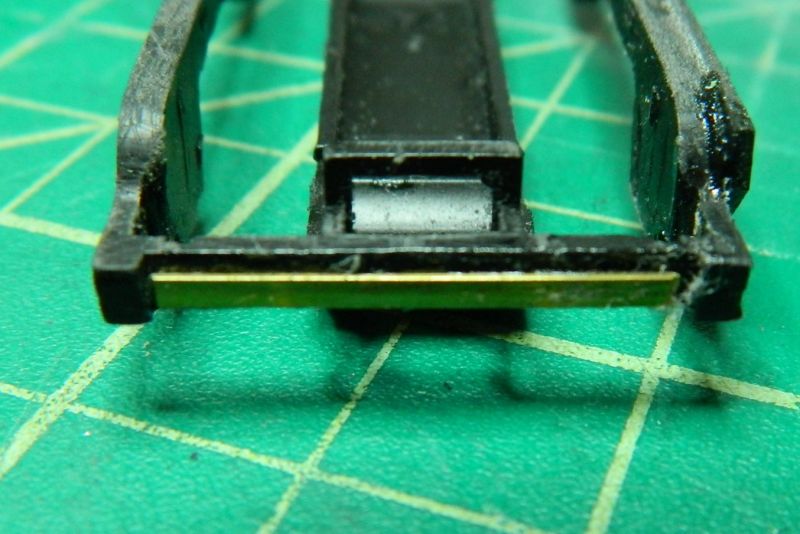
First job was to get the body shell off. Not clear in the instructions or parts diagram, but after a bit of poking around it's just a tab at the front and the back (which is where I think the previous owner gave up). So off with the shell. The good news it is not a split chassis, there is a decent sized can motor and flywheel. First job was a complete strip down of the chassis, a check of all the gears, and a good clean and lube, and it runs like a dream. However, what was masquerading as a circuit board was interesting and would have probably stopped the previous owner from going forward with the conversion if he had in fact got the body shell off. The "circuit board" collects power from the wheels and delivers it to the motor, and also powers the front light through 2 spring contacts attached to the underside of the boiler shell. No constant lighting resistors and 3v lamps, this is plain vanilla track voltage through a 12v lamp.
I'm giving it some thought, use the "circuit board" as a contact strip, or just gut it and replace with a decoder? Using the board means the decoder and speaker in the tender (and a mess of wiring in the boiler), decoder in the boiler means just 2 speaker wires to the tender. Space is tight, but I'm leaning towards binning the board and springs and rewiring from scratch. There just may be enough space for a sugar cube speaker under the chimney, as well as a mega-bass in the tender. Need to take some measurements, and metal will need to come off the chassis which ever way I go.
I wasn't going to post any of this, so no start picture of the locomotive, but it may be of interest to those contemplating a DC to DCC conversion.
Pictures below.
Nigel
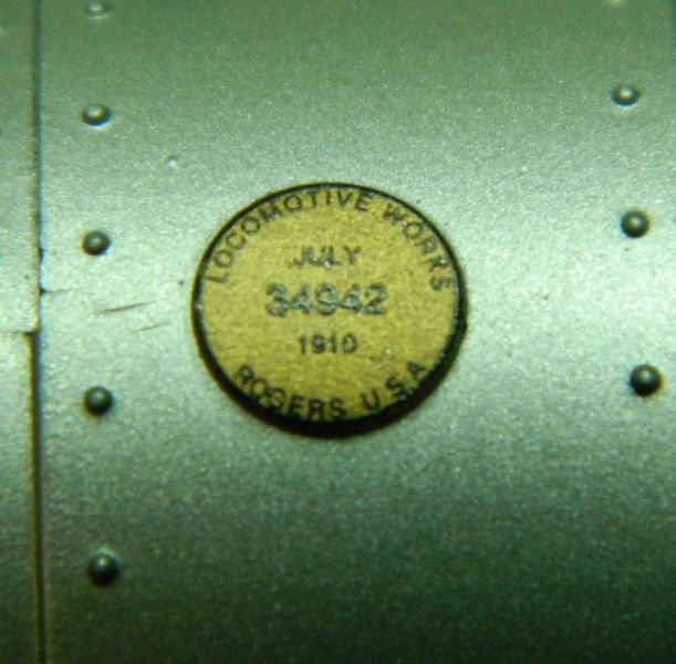
Photo from the box. Nice small narrow gauge mogul. .

Makers plate says "Rogers, 1910", which is probably incorrect, as Rogers were taken over by ALCO in 1905
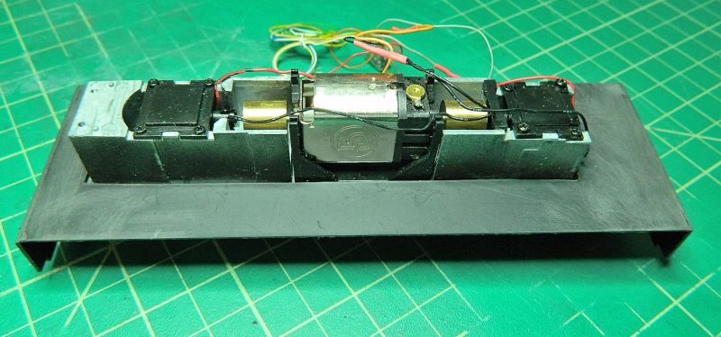
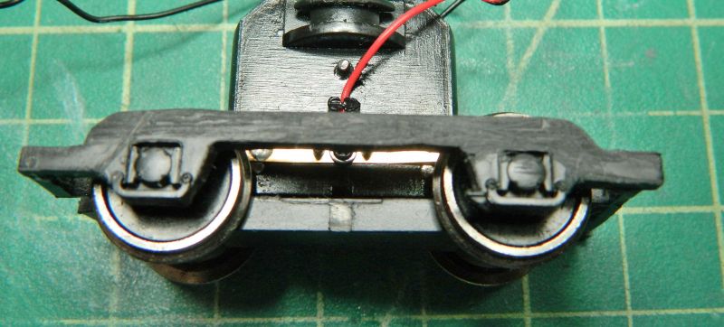
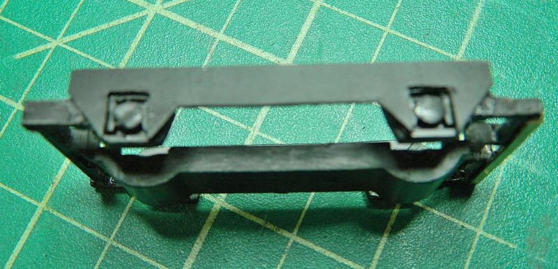
Running chassis after a clean and lube.
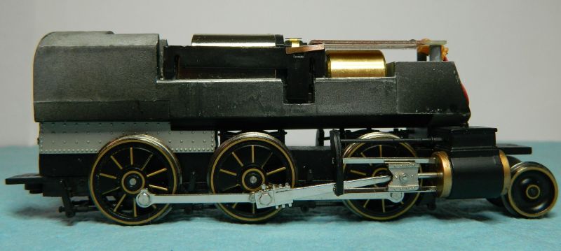
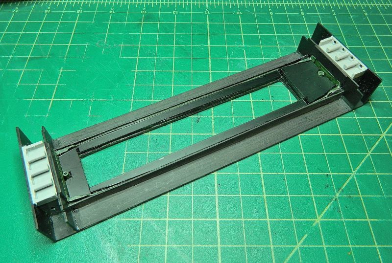
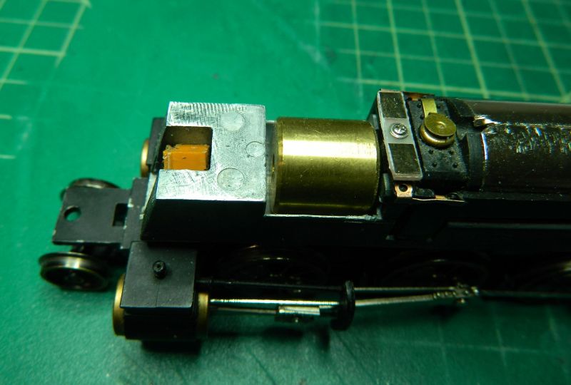
The "circuit board". Spring tabs to the motor terminals. 2-pin connector to the wheel pickups. Flywheel underneath.

Spring contacts to the front lamp which contact the "circuit board" board when the shell is in place.

©Nigel C. Phillips
Posted
Full Member
Too cold today to spray paint the B-B diesel with a second coat of black, so a bit more work on the On30 2-6-0.
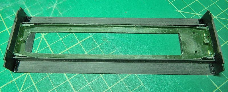
After much measurement and checking decoder sizes, I decided to put the decoder in the tender, along with a mega bass speaker, and to hopefully put a sugar cube speaker in the boiler. That gives me enough room for a 2 amp decoder with a 2 watt sound amplifier. So out with the Dremel and the big files to do some metal removal. I'll need to have the red/black wires going from the pickups to the tender, orange and grey back to the motor, front headlight wiring (2 wires) and speaker wiring (2 wires) from the tender to the lights and speaker. Plus connectors so the tender can be separated from the engine. The last two sets of wires only need to carry around 150 mA (if that, but that's the aux output on most decoders, and a 2 W amplifier running at full output at 12 V is around 170 mA, so 50-75% max volume should be fine). The plan is to use a big dome stack with spark arrestor instead of the small cylindrical one supplied, and to open up the hole in the boiler top (Blodgit and Fudgit's philosophy of sound rising. "Only makes sense, guv! Big 'oles, more noise!" "Think of the neighbors" I say. "They're deaf". Lost cause these two).
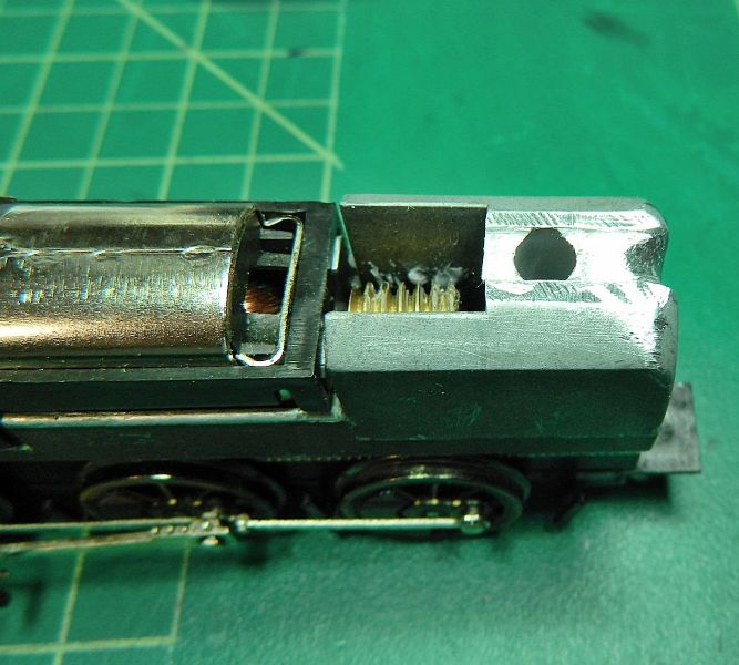
Nigel
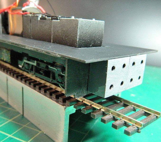
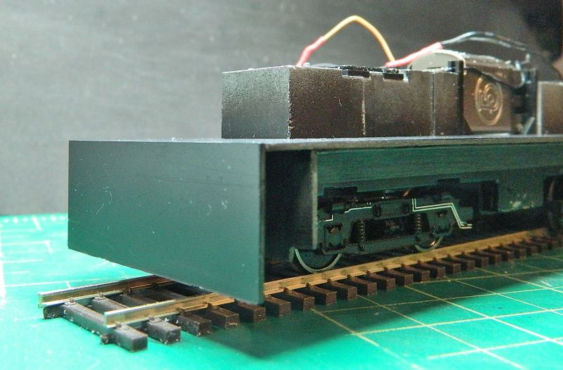
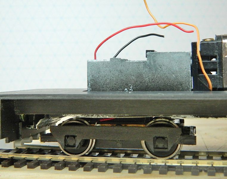
Front end. I removed the "circuit board", cut the support pegs off with a cutting disc in the Dremel, and tidied up with the file, I cut a piece off the board to provide some decent sized soldering pads for the orange/grey wires, I'll need to drill a couple of holes top to bottom for continuity. I should have some Vero board in the spares that's already drilled and tinned, if I find it I'll use that instead.
Back end. I reduced the height with the big file, and cut a groove with the Dremel and a grinding disc.I should be able to ru the wires down the back and underneath the cab floor.
©Nigel C. Phillips
1 guest and 0 members have just viewed this.