Gladiator B16/1 A North Eastern Workhorse
Posted

Full Member
The completion of the build of a 7mm scale B16/1
Hi Nigel,I must admit that pretty much the first job that I did with the Proxxon was to replace the collets which didn't go down small enough with mini chuck which will hold very small drill bit's
Regards Rob

Posted
Full Member
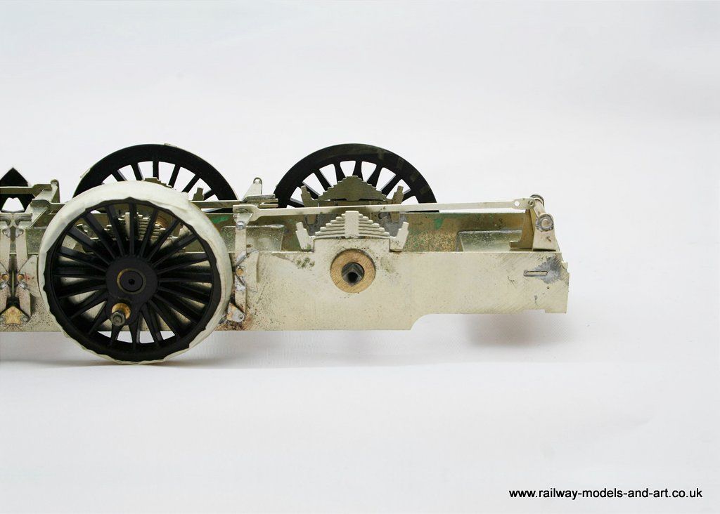
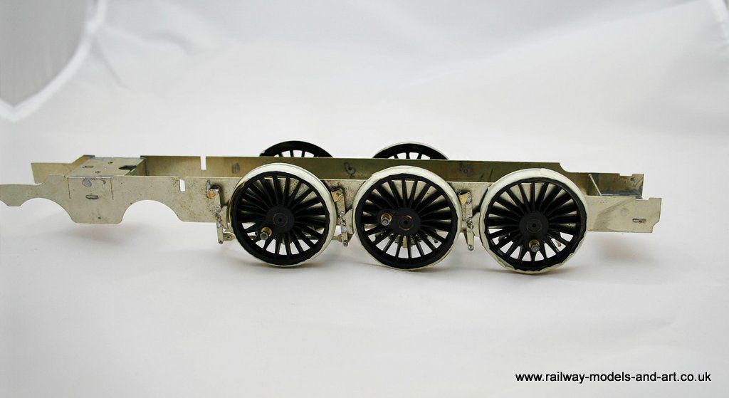
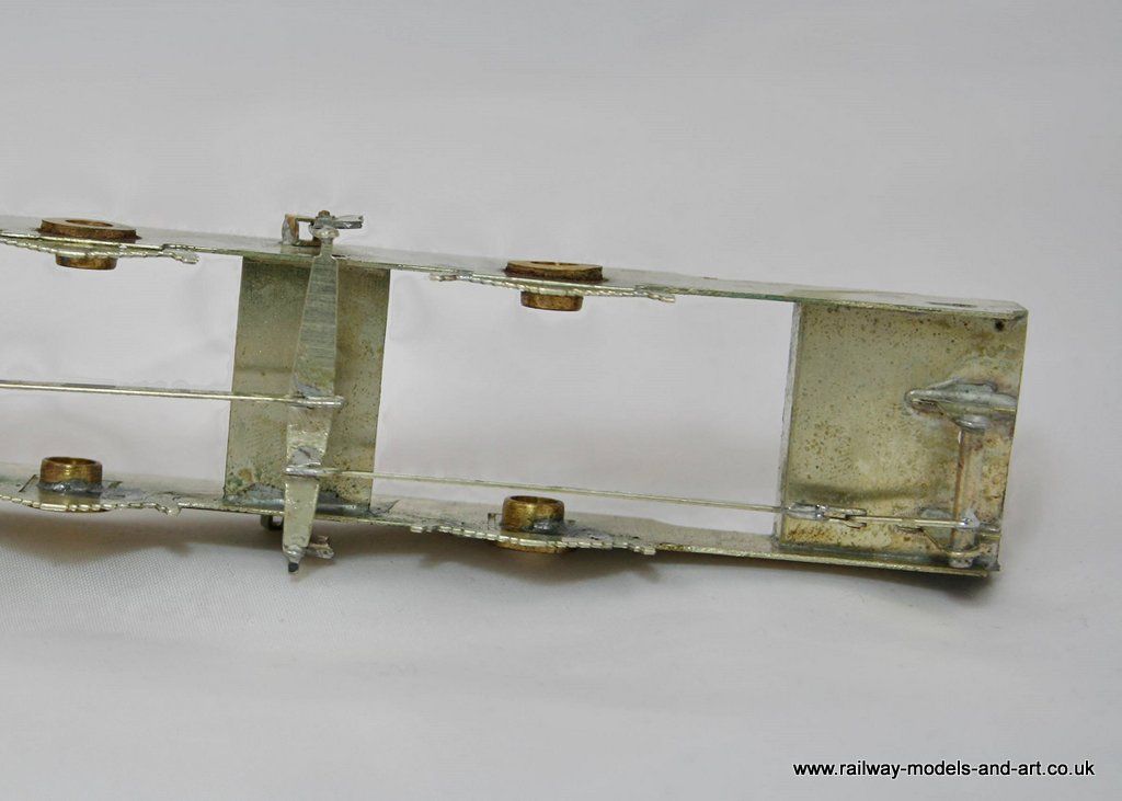
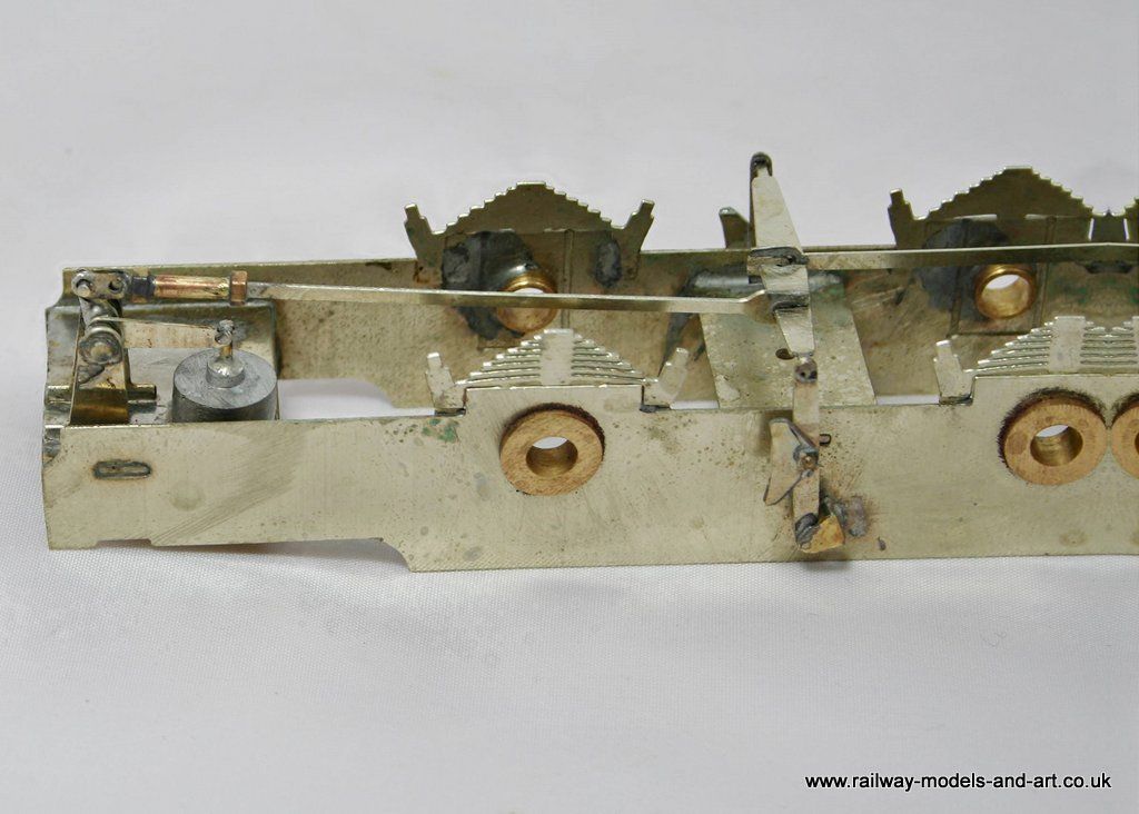
I wound a few layers of masking tape around the wheels to both space the brake shoes away from the wheels and to help reduce the risk of rusting from soldering with the wheels in place.
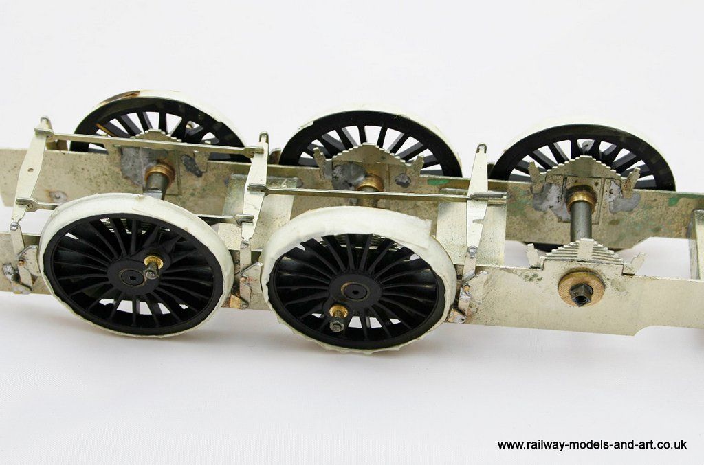
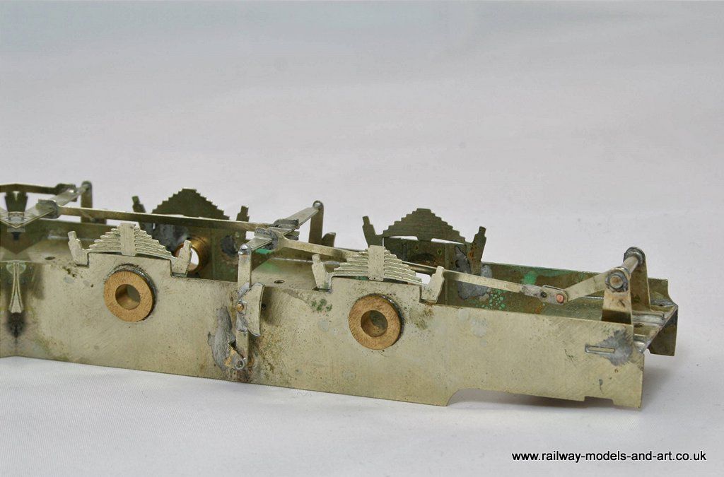
I was forewarned by a gent on RMweb who has recently built a 4mm version of this kit that the length of the yokes that fit to the brake spreaders is a bit long and so it was with the 7mm version. I used a diamond disk in the Dremel to cut a slot in the brake spreader to allow the fork in the yoke to slip back and effectively shorten the rod. - see photo above.
I also need to shorten the rod that connects to brake the the link below the ab too. The plan is to solder a piece of scrap to the end with the boss on and file a second boss which will allow me to create a forked joint once I shorten the rod.
Regards Rob
Posted
Full Member
Which I duly did on Wednesday night. In fact I was feeling pretty pleased with myself until this morning when by chance I found a photo which showed me exactly how the brake gear should fit at the cab end.I also need to shorten the rod that connects to brake the the link below the ab too. The plan is to solder a piece of scrap to the end with the boss on and file a second boss which will allow me to create a forked joint once I shorten the rod.
It will be good news to David (Hill) that in fact you don't need to shorten the rod to the cab rear at all, you just need to connect it to the right lever from the cross shaft.
All being well I should have it corrected on Monday evening and I will post before and after photos to show how I got it wrong initially. In the hope that it will prevent someone else from making the same mistake. I have say that the instructions are lacking in this area being of the 'fit parts X,Y,Z,' styke and an email to Steve Barnfield although it elicited a response didn't help because he couldn't remember how it fitted.
To give Steve due credit he did offer to assist in person if I was in his area but I am a long way from him.
Regards Rob
Posted

Full Member
John
John
Posted
Full Member
Yup!Well, I hate it when that happens…and it does. :cool wink
John
 …..
…..
Regards Rob
Posted
Full Member
Hopefully this will assist anyone when they get to this point in their kit.
NB my subscription to PhotoBucket seems to be retaining my images at present so I will continue to use it. If it goes pear shaped all the images are available on Flickr and I do have back ups so I can re-instate them on this thread at least.
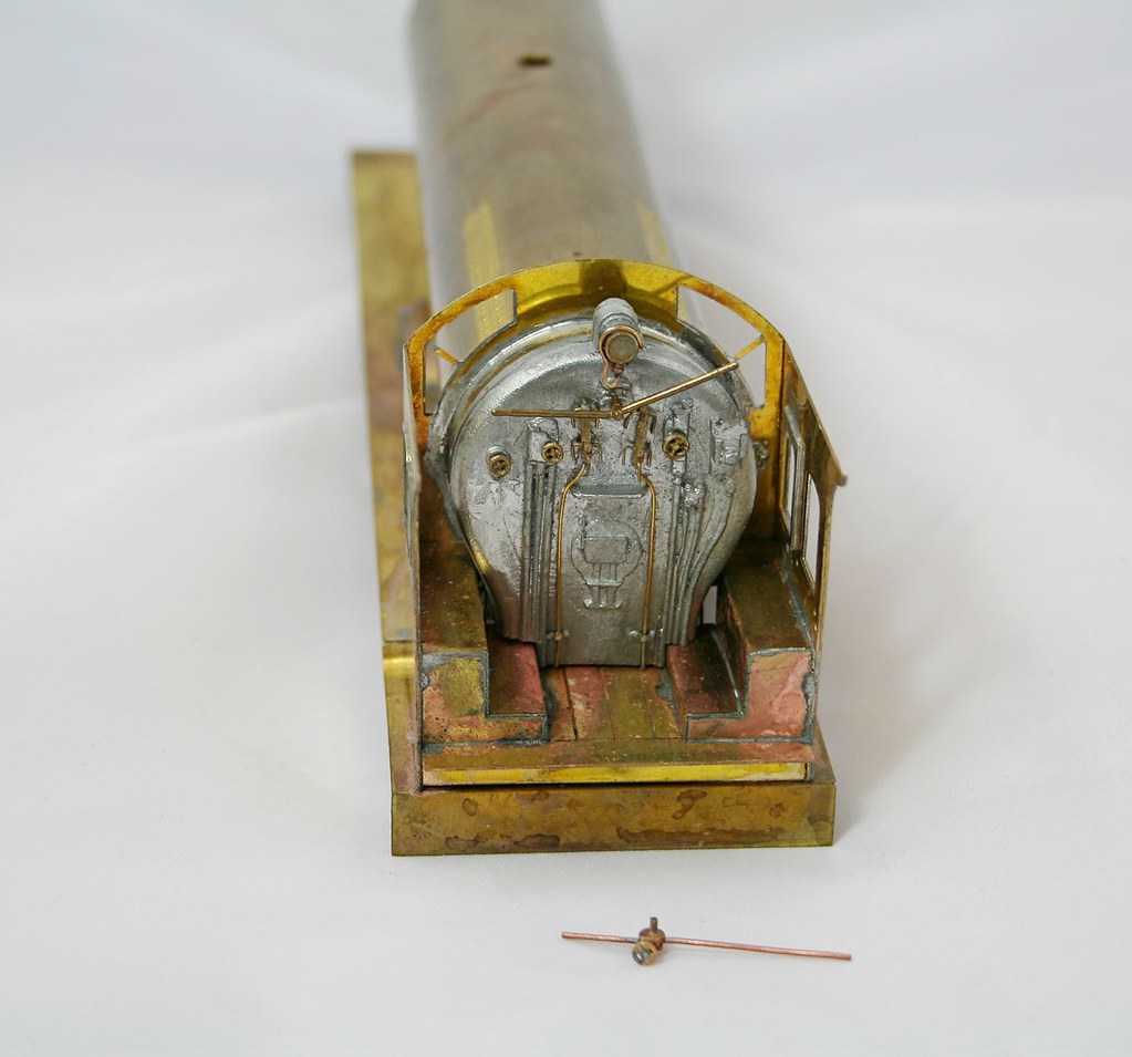
This is where I had got to in my ignorance last week.
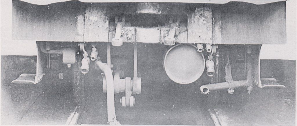
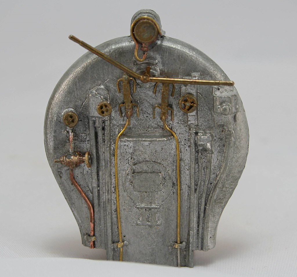
This is what it should have looked like - this is a crop from a photo of an NER V Class, which is referred to in the instructions as having the same backhead details as the B16 it was only after spending sometime studying the backhead that I realised that it also showed how the brake gear fits at the cab end.
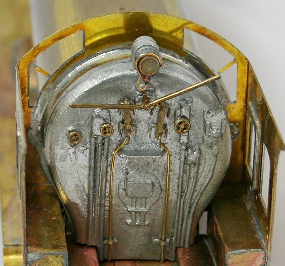
Then this is the result of last night's efforts - I had to add a representation of a slack adjuster to make up for my shortening the shaft previously
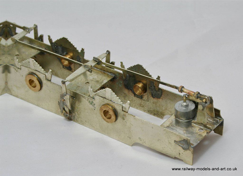
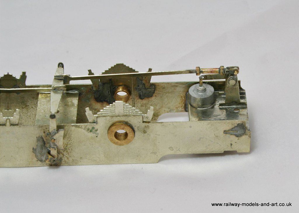
Finally not the best shot in the world but it does look more like the real thing now
Regards Rob
Posted
Full Member
John
John
Posted
Full Member
So do I now, to be fair I was happy in ignorance too :cool winkOoh I do like the brake detail. :chicken
John
Regards Rob
Posted
Full Member
John
John
Posted
Full Member
Time has been spent since getting back on the little things that take time and don't seem to evidence much progress but all add to the overall picture.
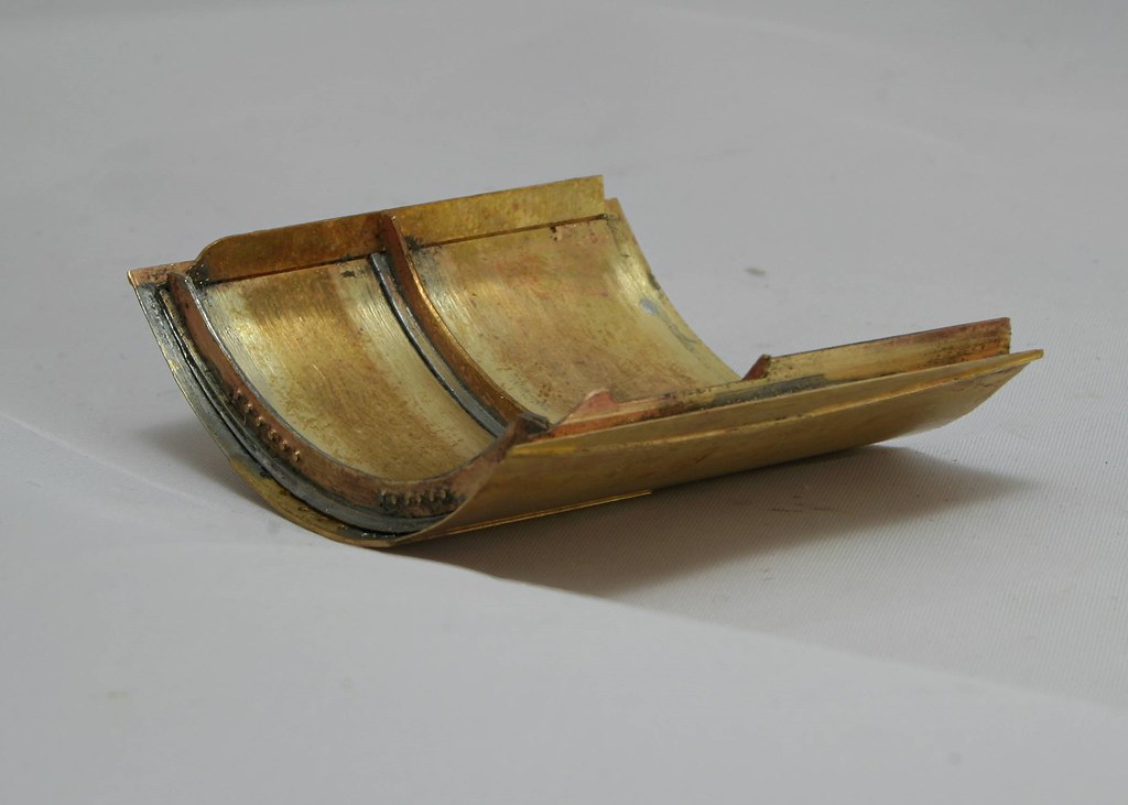
I have started looking at the upperworks starting with the cab fittings. A lot of the detail is cast on to the backhead and there are some castings supplied. Sadly a lot of the detail is a bit low relief so I suspect that I will remove and remake most of it.
I add some fine brass wire to the gauges
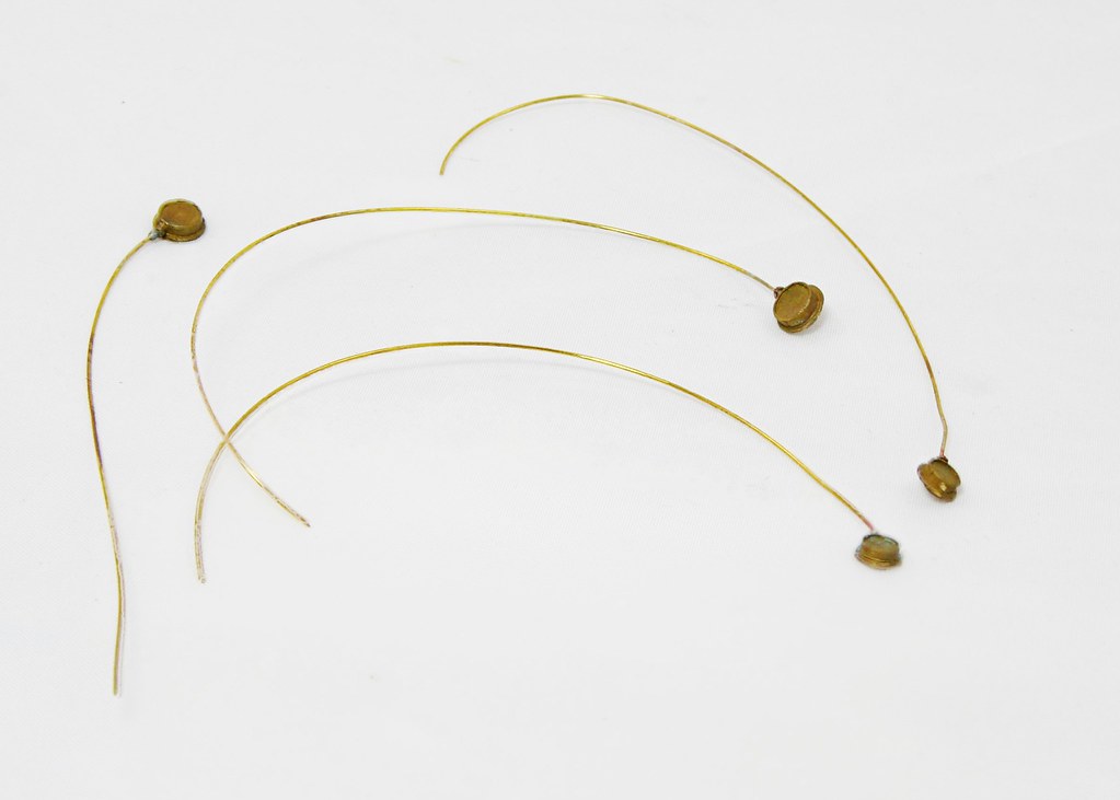
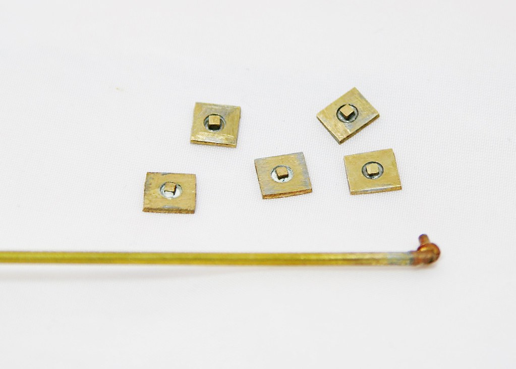
I also made up some washout plug bases these are two layers of brass with a stub of square section brass inserted. The plan is that this will be soldered behind the holes in the firebox and then half etched surrounds soldered over them. A length of square section was included in the box but I am unsure as to whether this comes with the kit or it was provided by the owner.
I also soldered the elbow provided onto a length of tube for the vacuum ejector pipe.
Regards Rob
Posted
Full Member
Detailing those gauges is neat, something to bear in mind.
My J50 should have what I think is an ejector pipe but doesn't. I've been trying to gather the courage to drill into the boiler. :shock: Funnily enough of all the pictures I have seen of the J50, the picture on Hornby's website of their J50 is the clearest.
John
 Last edit: by Brossard
John
Posted
Full Member
Thanks John,Nice to see you back Rob. I was wondering where you'd got to. Off for a paddle no doubt. :Happy
Oh yes, Norway and Iceland. Until we got there I hadn't realised just how close to Greenland Iceland is.
Regards Rob
Posted
Full Member
John
John
Posted
Full Member
It was, it comprised of a couple of stops in Norway, then across to Iceland with 3 stops (including a couple of days in Reykjavik) and then a stop in Dublin on the way home.
Regards Rob
Posted
Full Member
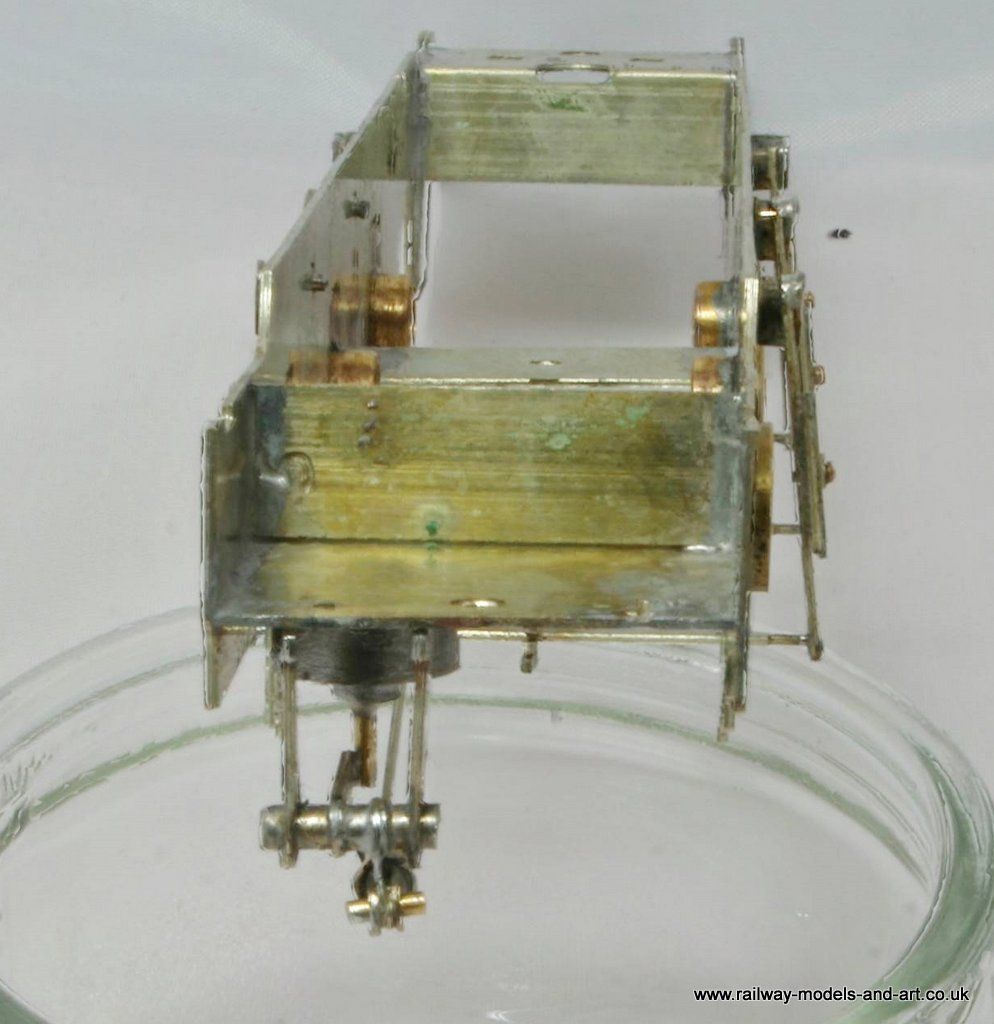
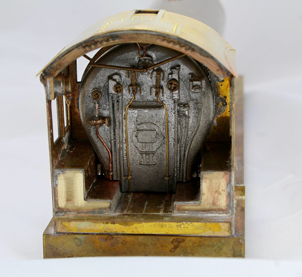
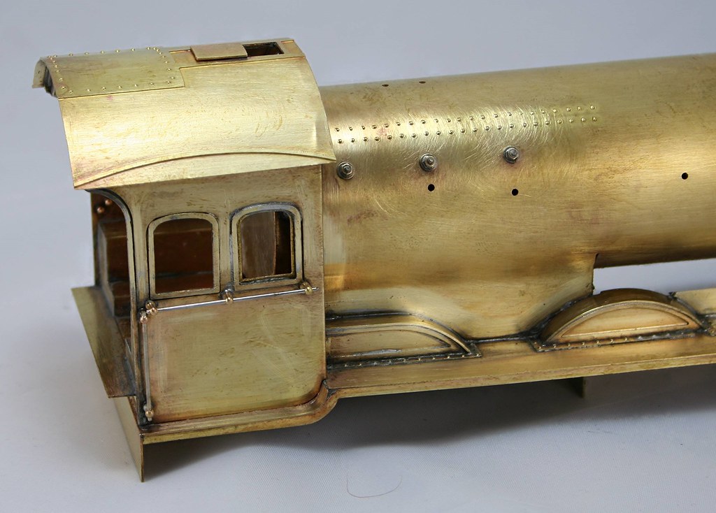
I have added the lockers/splasher tops inside the cab and cut the backhead to fit. I have also done most of what will be replaced with just one casting to fit tonight. - shown below the cab rear. This will fit to the left of the backhead below the hand wheel and where the ghost of the cast pipe can still be seen - must do a better job of smoothing it of before putting the new one in place. The pipe work for the water gauges is very fine and a bit flimsy so I knocked up a couple of pipe clips from scrap and soldered them in place. I suspect that I will need to do the same with the final pipe when I have it in place.
Regards Rob
Posted
Full Member
 ]
]
You can see where I had to make a cut out for the plinth to fit.
 ]
]
Regards Rob
Posted
Full Member
The tender is now complete with it's missing Vacuum pipe and axleboxes and just needs a good scrub before I take any photos.
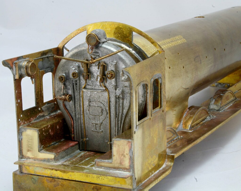
From the previous photos I have fitted the cab roof and working back from the cab I have also fitted the cab side hand rails I also started work on the washout plugs, and for the upper part of the firebox in the timeframe of this model, the oval base plate had been replaced with a round one.

 ]
]Last thing, I gave it a good clean up scraping off lots of the excess solder that had built up in various areas.
Last edit: by Rob Pulham
Regards Rob
Posted
Full Member
John
John
Posted
Full Member
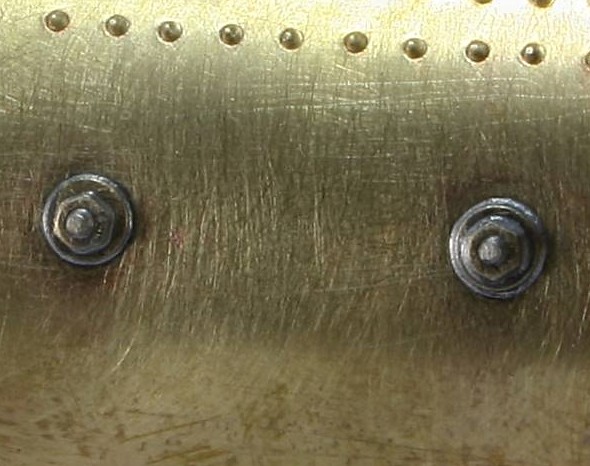
In hindsight I probably could have got away without threading the rod and drilling out the nut's but either way it didn't take long and I makes them doubly secure.
Regards Rob
Posted
Full Member
Not much modelling done this week due to not being at my best, but a bit of thinking in the lucid moments and looking at photographs of B16's. The conclusion that I reached is that washout plugs on B61/1's are a nightmare. Almost every photo you look at has different numbers in different positions - No Swindon standardisation here…
So I settled on the understanding that the loco that I am building '61450' had three on the right hand side and two on the left (looking forward from the cab). 61450, would also have to be one of these with the foremost washout plug on the front corner of the firebox. Working out how to do that took a bit of head scratching.
As I have said before, mostly those things that require most head scratching and trepidation prove to be simpler to just get on and do. So it was with this one. I marked off where each one would sit and drilled a small pilot hole. For the four that are sat square to the side I just kept using slightly bigger drill bits until I hit the size for the previously made backing plugs.
For the one at the corner of the firebox, I drilled a pilot quite close to the edge of the side of the firebox and again started to make it bigger. I stopped short two or three sizes smaller than I needed for the others and then using an oval diamond file, I filed the front of the firebox adjacent to the hole so that I had a 3/4 hole in either face of the firebox. I then used a round burr in my Dremel to ease it to final size.
Fitting the backing plugs and getting them in position was fun, it took at least three attempts on all but one of them. Once they were all soldered in place it was time to add the half etched overlays to the firebox sides around the holes. I tinned them all while still on the fret then cut them out and filed of the tag.
I decided to use the microflame to solder them in position because I reasoned that using the soldering iron (aside from the possibility of getting solder all over where I didn't want it), would possibly nudge them out of position too. This created the dilemma of heating the front face while making sure that the plug didn't drop off the inside of the firebox. to get around this I cut some short lengths of coffee stirrer and wedged them between the two washout plugs inside the firebox and away I went. - I did manage to set fire to one which gave Chris a bit of a moment….
On a couple I had to add the tiniest spec of extra solder to get them firm and the one folding around the front of the firebox took a few attempts to get it seated properly in both planes but I got there in the end. They still need cleaning up but not as much as they would have if I had attempted to use the iron to solder them on.
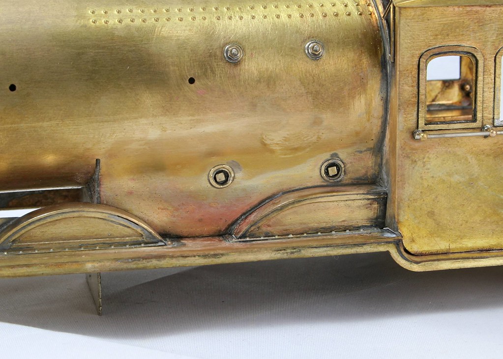
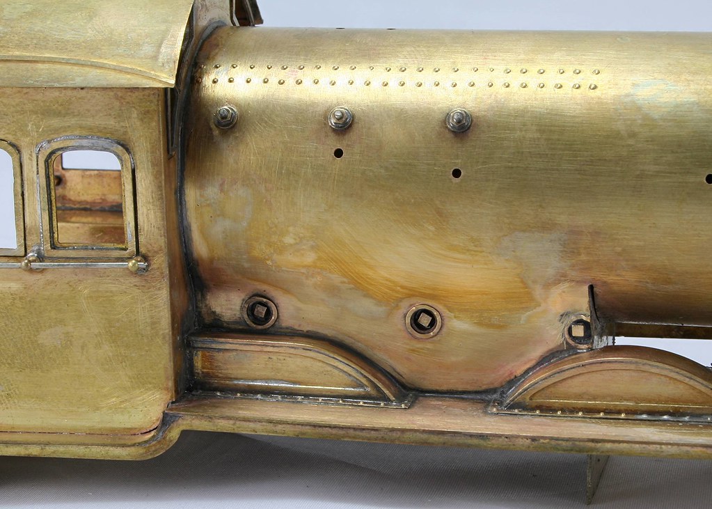

They are one of those details that will fade away once lost in the overall paintwork but which would be very noticeable if they weren't there. The plus point is that now that I have done them once doing them again on other locos will be quite straightforward.
Last edit: by Rob Pulham
Regards Rob
1 guest and 0 members have just viewed this.