Gladiator B16/1 A North Eastern Workhorse
Posted

Full Member
The completion of the build of a 7mm scale B16/1
True, but you would be amazed at the number of official LNER photos in the Great Northern Railway Engine Shed volumes that have LMS wagons in the photo with not an LNER wagon to be seen.
 Last edit: by Rob Pulham
Regards Rob

Posted
Full Member
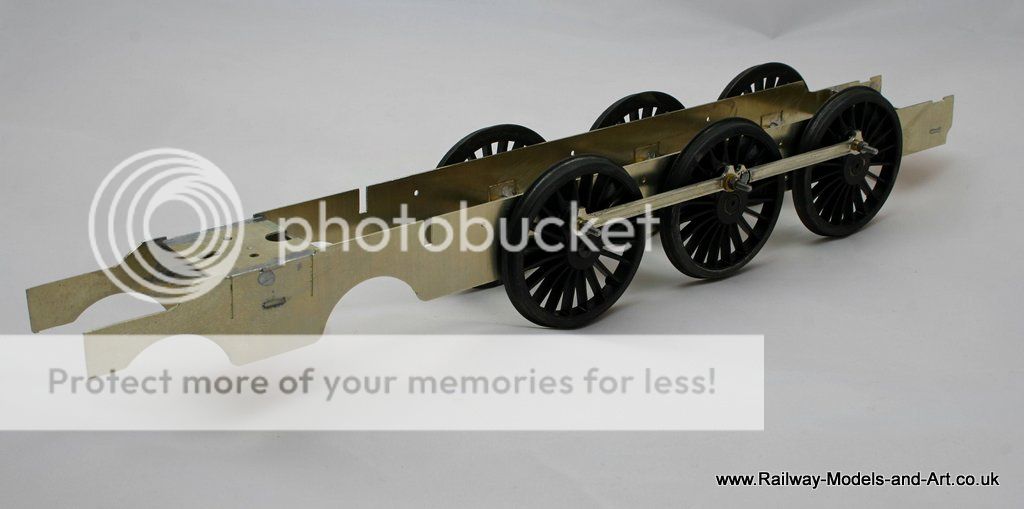
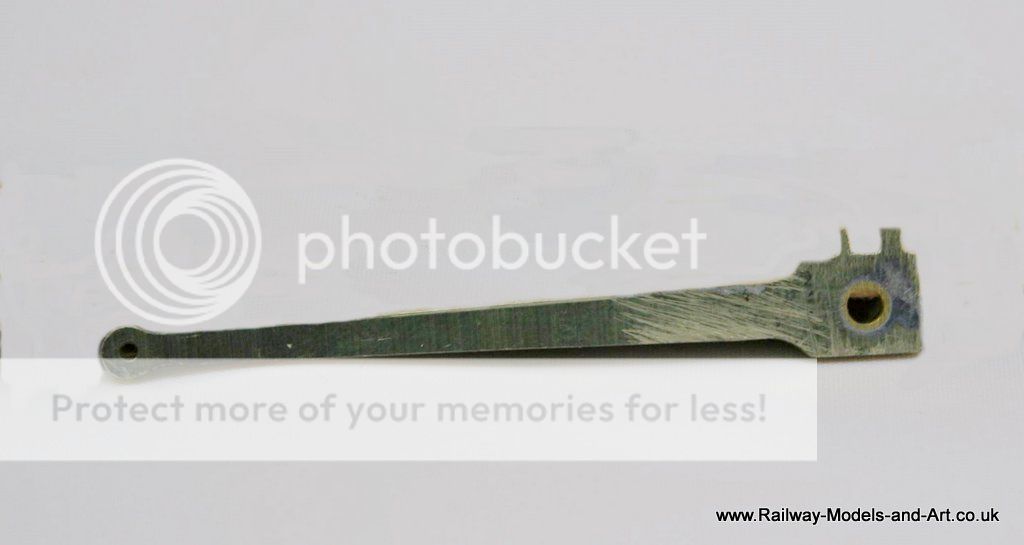
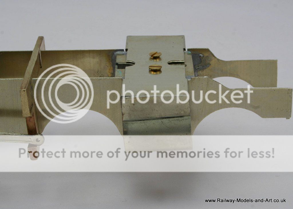
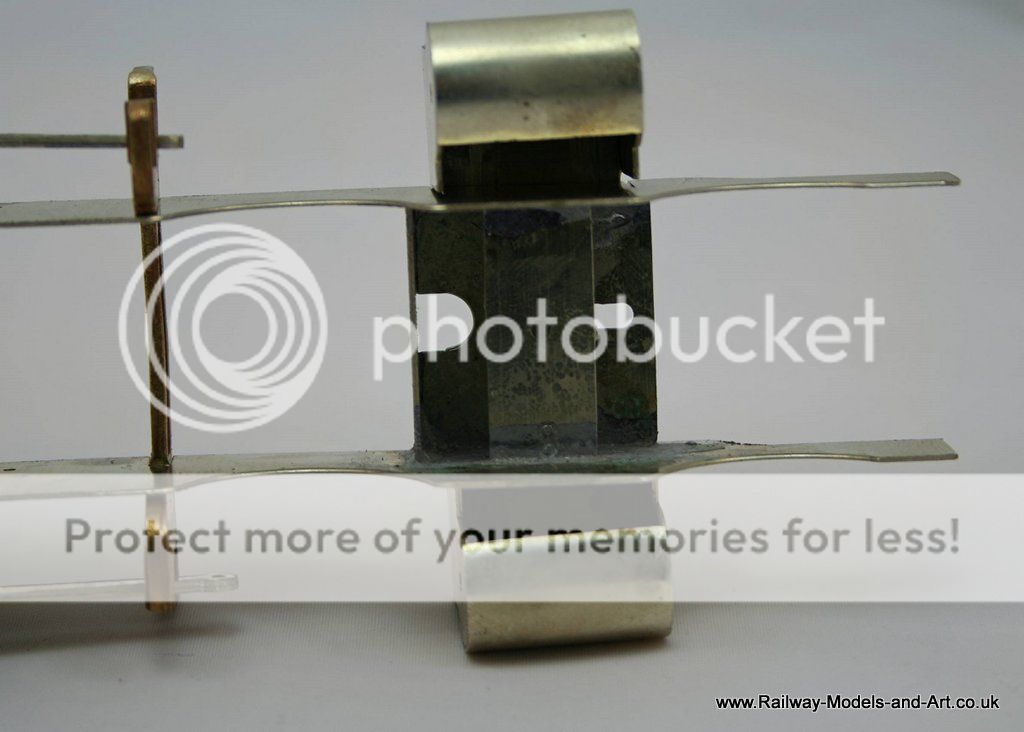
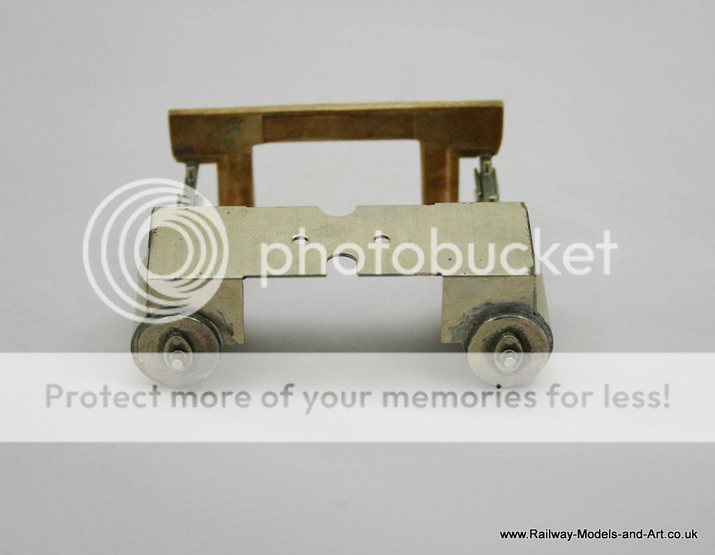
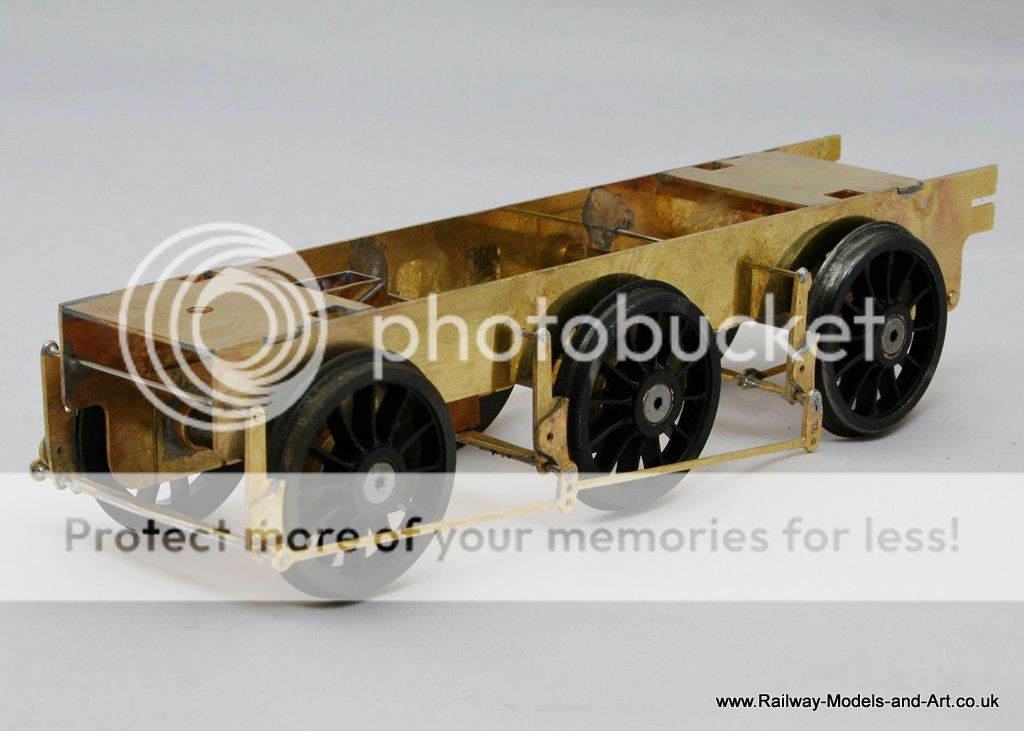
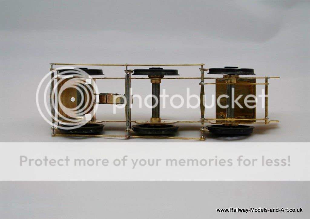
Although the chassis is rigid the rods are designed to be jointed and it made sense to do so. The recommended method in the instructions is to use a 10 ba cheese head screw (supplied) which you put through the rod and solder to the rear layer (putting a piece of paper in between to prevent soldering it up solid). You then file down the screw head until all traces of the slot are gone and you are left with it looking like this.
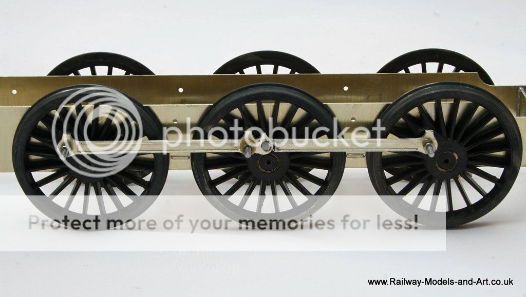
*Note* the washer that you see on the centre axle is just there to support the joint/stop side play on the rods while I tested it before I finally shorten the bushes and screws.
Regards Rob
Posted

Full Member
Yes that is very true, foreign goods vehicles tended to be scattered far and wide. I was thinking more of locos and passenger stock which, in the main, tended to stay on home lines. These take a great deal of time to make if you are doing kits.True, but you would be amazed at the number of official LNER photos in the Great Northern Railway Engine Shed volumes that have LMS wagons in the photo with not an LNER wagon to be seen.
John
John
Posted
Full Member
Oh yes, that's why I have drawers full of loco and coach kit's and not that many built so far.I was thinking more of locos and passenger stock which, in the main, tended to stay on home lines. These take a great deal of time to make if you are doing kits.
Regards Rob
Posted
Full Member
John
John
Posted
Full Member
Regards Rob
Posted
Full Member
John
John
Posted
Full Member
Yesterday's bench session centred on the connecting rods, cylinders, slide bars and cross heads.
When I came to try the connecting rods I found that on these the holes are etched slightly over size even without taking out any etching cusp which would probably wear away quite quickly. The answer was to use a bit of brass tube that fit snugly over the crank pin bush to create a bush. I reamed out the con rods to take the outside diameter of the tube, cut a couple of short lengths end ensuring that one end of each piece was flat. I place the piece flat side to the face side on the con rode and soldered it in from the rear. I then filed the rear smooth.
Next up I cleaned up and straightened the slide bars and piston rods etc. to get a nice clean smooth sliding fit. To be honest although it took a couple of hours, it was more tweaking to straighten the various bits than filing much off. Although I did go over the sliding bits with fine well used wet and dry to polish them at the end.
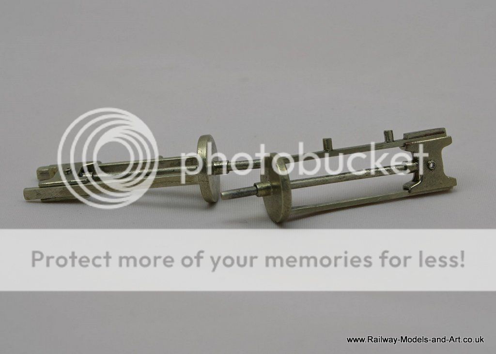
Then I did the same with the motion bracket. The kit is designed so that it just sits in the frames and once the slide bars are attached it allows the cylinders and motion to be removed as a single unit. It required a bit of straightening and bit of filing to get it to sit over the frames without pinching them.
I note from the photo that there still appears to be a slight bend in the middle, but its a nice fit so I am not inclined to upset that by attempting further straightening where it won't be seen.
Last but not least was fitting the cylinder covers. This is always an interesting challenge, made even more interesting in this case by the slope of the cylinders. The instructions advise that the covers have been made over size to allow fitting and filing back. They are, but only just and another millimeter on the overall width would have made the job so much easier. There is talk about annealing for such bends but since the covers are half etched and like many tasks was much easier in the doing than the thinking about before hand.
The hardest bit was holding it all in place once shaped to solder it. I prefer to use the microflame to solder where possible and I made much use of four pairs of self locking tweezer to hold one side in place before adding flux, a short length of 145 solder and applying the flame. This was repeated and the first cover was nicely in place just needing the overlaps fining off.
Maybe I was getting complacent or perhaps it was because it was about quarter past eleven last night, but the second one fought back. Each time I soldered one section another bit came loose, That's despite having lot's of clamps in place but I got there in the end.
Despite the soldering problems with the second one it was still much easier to do in practice than I had built it up to be in my mind before starting the job.
The length of the covers also fall short of going right round the cylinder. I was tempted to put in a bit of scrap to fill the gap but having read the various notes on clearance at the back of the cylinder I will leave that until I have tested it.
Regards Rob
Posted
Full Member
John
John
Posted
Full Member
I the slide bars installed on the motion bracket after slowly working my way backwards with the filing until the cylinders were in the right place.
you can see from the inset photo in this image how much I had to take it back. I did it in three stages checking the fit after each stage.
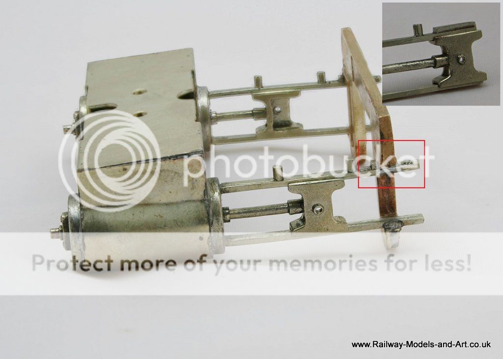
I shortened the piston rods a bit so that they fit inside the slide bars with approx. 2mm protruding from the gland on the inside of the cylinder. Now that I have it all assembled I will fit the connecting rods and cut the piston rods to final length.
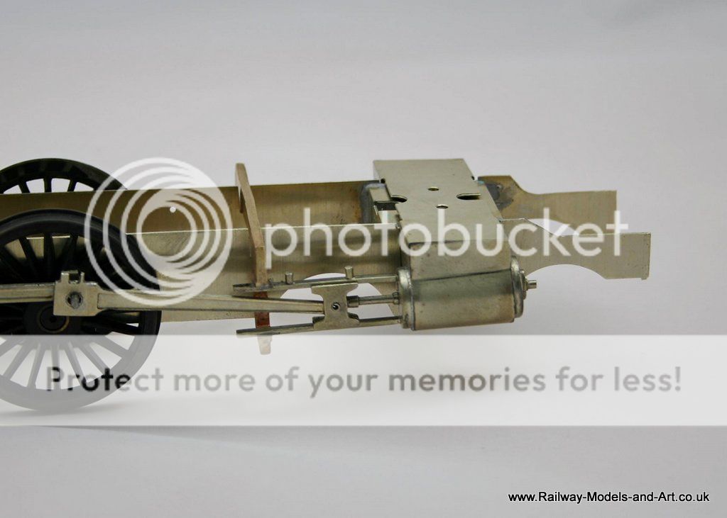
The close ups show that I still have a bit of cleaning up to do.
Regards Rob
Posted
Full Member
https://youtu.be/bGVp5L9NxD0
https://youtu.be/CfJxZw-F5B0
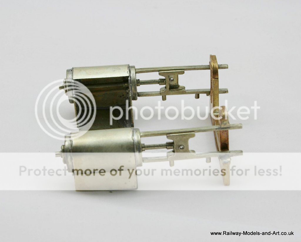
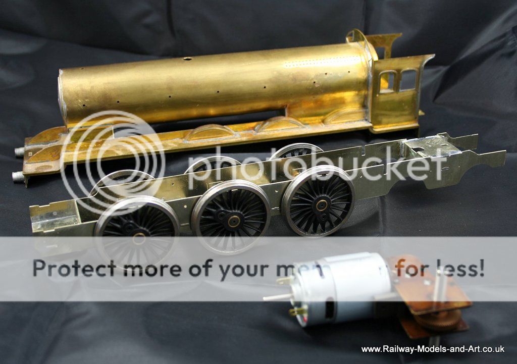
Unfortunately the motor is too big for the firebox as built so a smaller motor will be sought.
Regards Rob
Posted
Full Member
What's the device? It looks like a rolling road/chassis jig.
I have the Avonside and got myself pins to suit 7mm locos a couple of weeks ago. It will do for short wheelbase locos.
John
John
Posted
Full Member
It's the Hobby Holidays chassis jig. As well as being a chassis jig it also comes with the bits to make it a rolling road.
It's great apart from when you have a finished loco that you have added weight to as it then has a tendency to tip forward so you need to weight the back of it.
Having a 2-8-0 and a 2-10-0 in the pile when I bought it I opted for the 5 axle version.
Depending on what it's like I am collecting an 01 2-8-0 from the E&T service at Leigh show tomorrow. If it's not up to much I may well come home with a Connoisseur J50 instead.
Regards Rob
Posted
Full Member
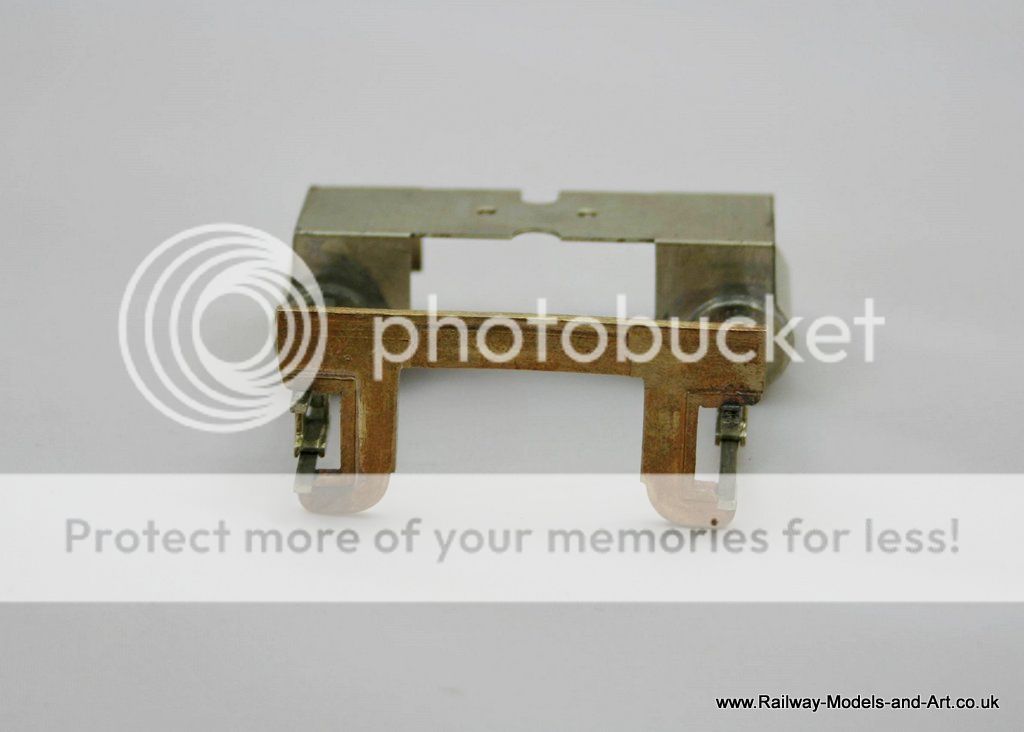
I always seem to struggle with setting up brakes that are produced from etchings in that they seem to want to move in all directions when you are trying to solder them. I came up with the idea of wrapping a couple of layers of masking tape (the cheap kind not best Tamiya!) around each tyre which not only creates a gap against possible shorts but it also keep the worst of the flux from the wheel too. This allowed me to lean each shoe against the wheel and with the aid of some locking tweezers I was able to hold it in the right orientation while I soldered it.
Within the kit there is only one brake spreader for the front set of brakes. The rest are just represented by 0.7mm rod. I chose to file up a couple more from scrap etch and solder them on top of the pieces of rod. This not only looks a bit better for the few minutes that it took to do but it also gives a shoulder to space the brake shoes apart - again solving one of the potential directional shifts while trying to solder them.
You can't really make it out in the photo but the forks in the two actuating rods that come from the front to the first spreader are slightly two wide for the single layer etch of the spreader. I could have nipped them closed a bit and just soldered them but again it was only the work of moments to wrap a couple of pieces of the half etched tags that I have cut of the various parts around the spreader and once the etching cusp was removed from the forks a much better fit that again held itself in place while applying the solder to it.
In reality the water scoop would fit below the brake spreader but in the interests of not having it catching anything on the track while running I soldered it to the top of the spreader. Once the outer frames are in place not much of it will be seen so I chose safety over accuracy.
The added spreader certainly improves the look from the rear of the tender.
Regards Rob
Posted
Full Member
You may recall I have the Fine Scale Brass J50. There were 4 variants according to Isinglass. /1 and /2 were right hand drive. /3 (the one I have) was LH drive and only had steam brake (I'm a bit disappointed because I wanted to use it for passenger work - the hazards of buying without really understanding what you're getting). /4, also LH drive, had a "hopper" bunker. It did have vacuum brakes and steam heating but was only used for empty carriage working.
Brakes can be fiddly to fit, good idea with the tape.
John
John
Posted
Full Member
So far everything has fit as it should and the only minor concern is that the handrail holes look as if they might be a bit on the large side but until I have the overlays soldered on I won't know for sure.
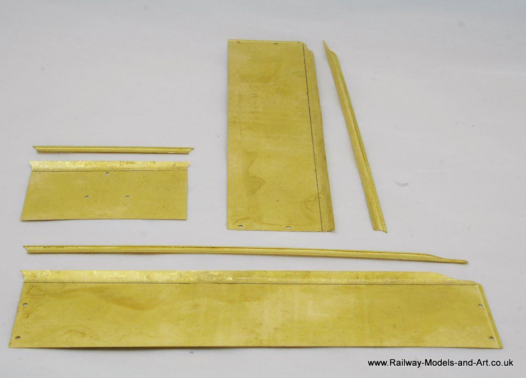
One of the cleverest bits of the kit so far is the tender flares. The tender sides have a half etched overlay that you have to create a flare on and then another half etched overlay to go over that for the just the flare. This means that although you have more flares to bend being half etched they are easier to form.
Although I initially wasn't looking forward to it, I recalled reading an article way back when I modelled 4mm, of someone who used a piece of rod in a vice and he squashed the flare against the thick rubber of a replacement shoe heel.
I didn't have a spare rubber show heel but I did have a set of rubber soft jaws for my proxxon vice (many thanks to Richard Lambert - Dikitriki for recommending the vice to me when I was having a look at his work in progress Duchess last year).
The instructions recommend using a 3/16th rod and I had some lengths that I bought for setting up chassis before I invested in my jig. I placed the overlay against the tender side and measured how much flare was above the side 4.5mm and drew a line at 4.5mm from the top across each side the the rear.
I placed the rod in the vice utilising the V groove for gripping round sections. I put a soft jaw on the other side placed the flare along aide the rod with the pencil line just visible and worked my way along using the vice to squash the flare against the rubber of the soft jaw. I had to go along each piece a couple of times until I was happy with the result and then I repeated the process for the small flare overlays.
I just need to solder them onto the tender sides now but that will be a job for tomorrow as an early night beckons before going to Leigh show tomorrow.
Regards Rob
Posted
Full Member
John
John
Posted
Full Member
Which ones, the main sides? The plan with those is to tin both sides with 1450 solder clip them in place with aluminium hair grips/self locking tweezers and then use the microflame to heat across it gently to get the solder to melt. What I haven't decided yet it is whether to add the upper flares before or after I add the overlays to the main tender sides.
Regards Rob
Posted
Legacy Member
Scary.The next build to cross my workbench is another one that's not for me but for the same Gent that I built the G5 for last year. This one is a finish it off build of a Gladiator B16/1
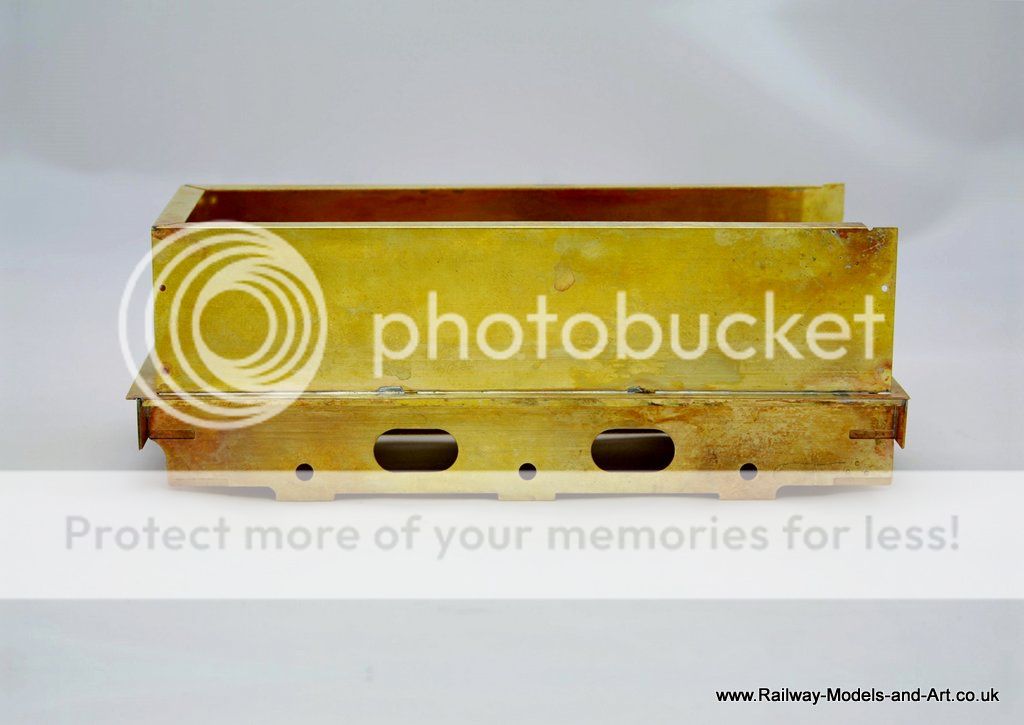
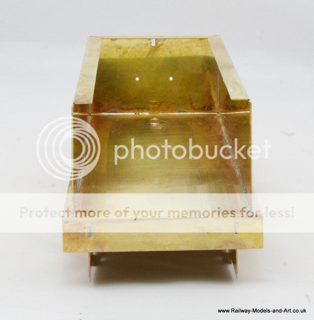
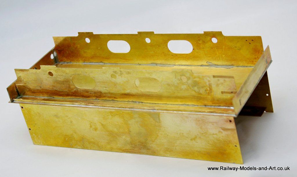
This is where I am starting from.
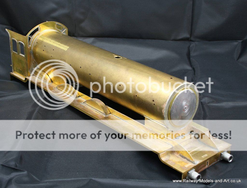
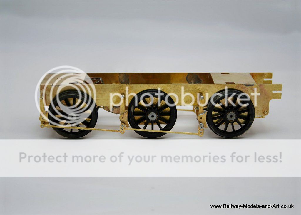
The main body work and the basic chassis are built. The chassis is to be rigid and pick up is to be by the American method.
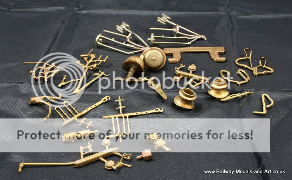
The kit contains lots of lovely brass castings
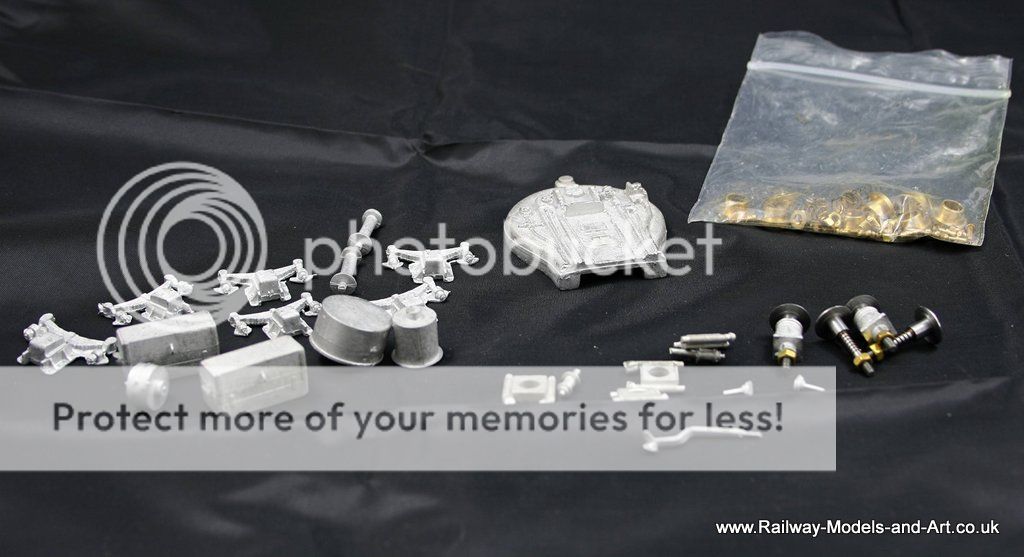
Plus some nice whitemetal ones too.
I have the week off and I will be at home the week after Easter so I plan to make a start on this then. Any spare time on between after finishing of the V4 brake van will be spent blackening wheels and preparing the castings etc.
Posted
Full Member
I was thinking of the large side and end pieces. Your plan sounds like something I would do and have in the past on 4mm models. The flame part is new to me.Hi John,
Which ones, the main sides? The plan with those is to tin both sides with 1450 solder clip them in place with aluminium hair grips/self locking tweezers and then use the microflame to heat across it gently to get the solder to melt. What I haven't decided yet it is whether to add the upper flares before or after I add the overlays to the main tender sides.
IMO the smaller pieces should be added later, the large overlay is unlikely to come adrift.
John
John
1 guest and 0 members have just viewed this.